Airside Network Components
Section 4 covers the following components, all of which can be placed directly on the airside network:
· Heating Coils
· Cooling Coils
· Spray Chamber
· Steam Humidifiers
· Air-to-Air Heat/Enthalpy Exchanger — Heat Recovery Devices
· Fans
· Mixing Damper Set
· Return Air Damper Set
· Junctions
· Ductwork Heat Pickup
Room components
There are a number of important points to note with regard to the arrangement of room components in the air system and the specification of supply airflow rates:
· A “Room” in the VE is any 3D space that is to be modeled as a distinct thermal zone. This can be multiple rooms combined in ModelIt as a thermal zone, a single room, or a subdivided potion of room volume, such as a perimeter zone in an open-plan space or the occupied or stratified zone within a space served by displacement ventilation. The ApacheHVAC “Room” component can also refer to a space that would not or could not be occupied, but which plays a role in the dynamic thermal interaction with HVAC systems. Examples include a return-air plenum, an underfloor air distribution (UFAD) plenum, a segment within an earth tube, a space within a vented double-skin façade, or even a concrete slab that will be directly heated or cooled by a hydronic loop.
· It is permissible to use the same room component more than once in the air system network description, such as when more than one system supplies air to the same room. For example, consider a case where room type A has separate air supplies for heating and cooling; there may only be one actual room type A, but we can use two in the system network description - one in the heating branch and one in the cooling branch. The result is exactly the same as if you had mixed the heating and cooling supply branches together through a combining junction and supplied this mixed air to a single room type A. The use of multiple room components in this way reduces the need for large numbers of mixing and dividing junctions.
· Once the system air has entered a room component, the program assumes that the air within the room (or bounded thermal zone assigned to a room component) is fully mixed. It is not possible to differentiate between, say, air entering from a ceiling diffuser and air entering from a perimeter unit or a floor outlet. You can, if you wish, describe a single room as several room types for the purposes of the computer simulation—e.g., the core and perimeter zones of an open plan office could be described as separate room types. However, you should appreciate that there are a number of complex mechanisms of heat transfer involved in such a situation (wind, stack, and induced air movement, radiant heat exchange, etc.) and the program can only approximately analyze some of these.
· Some situations are best modeled by putting two room components in series. For example, you may wish to model a building in which the return air is extracted via the ceiling void. This can be achieved by describing the occupied space and the ceiling void as two separate room types and then connecting them in series.
Direct acting units, radiators, and chilled ceilings can be added to spaces for heating and/or cooling purposes. Room units can be added to spaces contained within HVAC zones as well as directly to spaces in an un-zoned model. It is recommended that users work with Room components within ApHVAC, instead of Zone components, when large numbers of room units are to be implemented as editing of the units will be quicker and more efficient.
Zone components
ApacheHVAC users have the option to work with Zone components in order to gain access to associated features, or to work with Room components as in VE 2016 and other earlier versions of the software.
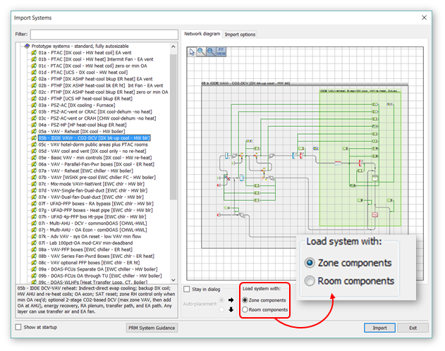
Settings in the ApacheHVAC Preferences dialog and the HVAC System Library Import dialog determine whether prototype systems will be loaded with Zones or Rooms and whether the Zone/Room placement tool will default to placing a Zone or Room component on the canvas.
When working with Zones, assignment of model spaces is by Zone or Zone Group. The group can be all zones on a system or any subset therefore, as might be desired for maintaining separate sub-groups within the Zone Groups.
Figure 4 - 1 : The default preference in ApacheHVAC is to load Prototype systems with Zone components. A radio button within the dialog allows users to load networks with Room components instead. A setting in the ApacheHVAC Preferences dialog allows users to change the default preference of the software.
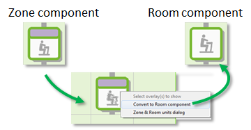
Figure 4 - 2 : Any Room Component on the network canvas can be converted to a Zone Components, or vice versa.
Direct acting units, radiators, and chilled ceilings can be added to spaces for heating and/or cooling purposes. Room units can be added to spaces contained within HVAC zones as well as directly to spaces in an un-zoned model. It is recommended that users work with Room components within ApHVAC, instead of Zone components, when large numbers of room units are to be implemented as editing of the units will be quicker and more efficient.
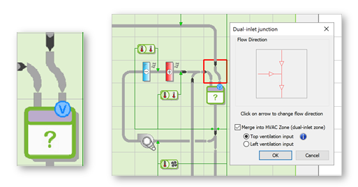
The air inlet of any Zone can be converted to a Dual-Inlet, with designated inlets for Ventilation and Space Conditioning. This is necessary for a system wherein Ventilation air is meant to be delivered separately to Rooms within multi-room HVAC Zones.* For example, in a dedicated outside-air system with ventilation air diffusers in each room and separately supplied airflow from zone-level fan-coil units, the apportioning of ventilation air and air for space conditioning needs to be separately determined.
Whereas distribution of air among rooms within a zone for space conditioning is by default according to the relative load in each space, the default basis for the distribution of Ventilation air among Rooms in a Dual-Inlet Zone is according to the relative floor area of the rooms.
*This is not needed when the space conditioning is at the Room level (as if there were a fan-coil unit in each room), as the rooms in that case would each need to be a separate zone with its own thermostat (i.e., air would not be distributed among rooms within a zone, as there would be just one room in each zone).
Figure 4 - 3 : A dual-inlet zone component is used when an HVAC Zone comprises rooms with Ventilation separately delivered to each room, and therefore this needs to be apportioned separately from the airflow for space conditioning.
Void components
Voids are a generic space type that is always unconditioned and is not a Return Air or Supply Air plenum. A void can have internal gains or air exchanges, but not Room Condition, System, or Plenum settings. A void is not auto-associated with an adjacent room (as Plenums are) and cannot be assigned to an HVAC zone (which comprises a set of conditioned spaces).
The VE does not assume a forced convection coefficient for voids, as this general space type has myriad possible applications. Many, such as a passive solar space, a double-skin façade, or an attic, would not include any form of forced convention. The heat transfer for such spaces, when they are used for any kind of plenum or earth tube, would depend upon specifics of the actual geometry, forced vs. buoyancy-driven flow and turbulence, applicable range of temperature differences, etc. Thus any pre-set value would be appropriate only in a small number of cases.
Plenum components
Supply Air Plenum and Return Air Plenum components facilitate automated assignment of 3D model plenum spaces to appropriate HVAC multiplex layers. Room-plenum associations are auto-detected according to adjacency in ModelIt and included in the HVAC Zones to which Rooms are assigned.
HVAC Zones assigned to ApacheHVAC multiplex layers thus come with plenum associations that drive the population of Supply Air and Return Air Plenum components.
Return Air and Supply Air Plenum components in ApacheHVAC automatically receive the assignment of plenum spaces in the model, as matched to the Zones or Rooms on the same layer of a multiplexed HVAC Network. Users can prevent the automated assignment of plenums if desired.
Plenums feature in the new Loads Reports, with detailed reporting for Return Air plenums in particular, and for both RA and SA plenums there is indication of the contribution to relevant coil loads at the time of the coil peak.
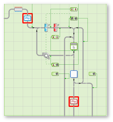
Figure 4 - 4 : Supply and Return Air Plenum components shown in an airside ApacheHVAC network