Toolbar button for placement of a cooling coil

Cooling coil component
Background
ApacheHVAC provides two levels of cooling coil models for use in HVAC systems. A Simple cooling coil model uses a simplified approach to determining coil heat transfer characteristics and assumes constant waterside temperature change through the coil. An Advanced model more explicitly models both airside and waterside heat transfer providing a more detailed and accurate calculation of coil heat transfer and corresponding airside/waterside properties. This includes modeling the coil in for dry (sensible), wet (latent), and partial dry/wet conditions. The Advanced model provides the necessary modeling detail to support explicit waterside modeling contained in Chilled Water Loop configurations. The Advanced model also provides more detailed coil specification methods so that coils may be better sized or selected from manufacturer data for specific HVAC system configurations. This facilitates more accurate determination coil design and off-design performance.
Both Simple and Advanced cooling coil models are accessed through the toolbar cooling coil button and cooling coil component dialog. An HVAC system configuration can contain both Simple and Advanced models, however, individual multiplex layer instances of a coil occupying a particular location must all be of the same coil model type (i.e., all Simple OR all Advanced models).
Simple models can be served by a Chilled water loop, DX Cooling, Water-to-Air Heat Pump, Unitary Cooling System, or Dedicated Waterside Economizer . Advanced cooling coil models can be served only by a Chilled Water Loop .
Simple Model
The Simple model requires only three input values to determine the coil performance: Contact factor, Cooling capacity, and Oversizing factor. The Simple coil is useful early in the design and modeling process when detailed coil data or performance is not required.
The simple coil model accounts for water temperature only when it is coupled directly to the dedicated waterside economizer component (not to be confused with the WSE option associated with chilled water loops, which require use of the advanced coil model).
In the case of the DX Cooling evaporator coil application of the simple coil model, the entering air wet-bulb temperature is also passed on to the DX performance model. See the section on DX Cooling for further description of this.
Advanced Model
The Advanced model is more detailed and accurate characterization of the heat transfer process of a cooling coil and its interaction with the water loop to which it is connected. The Advanced model uses more detailed coil design parameter specification and enhanced heat transfer modeling capability. One of the features of the Advanced model is the ability to design (i.e., “size”) the cooling coil for the specific HVAC system application. In this context, “size” refers to determining the coil heat transfer characteristics at a design point. With these design point characteristics, the cooling coil can then be more accurately modeled at both design and off-design operating conditions. To provide user flexibility two sizing methods (modes) are available: Autosizing and Manual.
In the first mode, Autosizing, the user specifies the coil Contact factor (similar to the Simple model) and then may invoke the System Sizing process to determine the remaining airside parameters necessary to size the coil. In the second mode, Manual sizing, the user specifies both airside/waterside conditions (and the coil Contact factor is determined from these parameters). Note that for both sizing modes, although coil contact factor is specific or determined at the design point, in the simulation contact factor will vary as coil operating conditions change. This ability to model coil off-design performance is a key feature of the Advanced coil model. More details on the two sizing modes is provided below.
An Advanced model dialog facilitates the two design sizing approaches by immediately “sizing” the cooling coil for the current state of design sizing inputs. Typical default coil design values are provided for both Autosizing and Manual modes. Editing a design parameter will automatically and instantly re-size the coil, and the new sizing parameters immediately displayed. A Sizing status message box indicates the state of the sizing process including error conditions resulting from out-of-range or inconsistent input parameters.
For each sizing mode, there are a set of derived parameters that are calculated upon user edit of any design parameter. For example, in Autosize mode the user sets (or can rely on System Sizing data) the entering airflow, entering air dry and wet-bulb temperatures, the leaving dry bulb temperature, and contact factor. The resulting leaving air wet-bulb temperature, chilled water loop flow, and cooling capacity are instantly calculated and displayed. If, for example, the resulting cooling capacity is too low, the user might increase the air mass flow or modify the contact factor to achieve greater cooling.
In Manual mode, the user has full capability to set all the design parameters on the airside and waterside of the coil. From these design parameters, the resulting coil contact factor, chilled water flow rate, and cooling capacity are calculated and displayed. Again, if for example, the cooling capacity is too low, the user might input a higher air mass flow.
Switching between the two design sizing modes is simply done by selecting the desired sizing mode button. The default dialogue mode is to only show the design parameter set for the selected mode, however, the user can display both modes data by specifying the Display mode to “both.” Finally, the user can “hold” autosized values when they switch to Manual mode.
Autosizing Mode
The Autosizing mode is designed to give the ease of specifying a single cooling coil design parameter coupled with the System Sizing feature to complete the required design inputs for the Advanced coil. In Autosizing mode, the user sets the coil Contact factor, then invokes the System Sizing process to populate the remainder of the airside parameters. These parameters, combined with the input Contact factor, complete the design point specification for the cooling coil. In addition, prior to or after System Sizing data has been obtained, the user may also change any of the autosized parameters (or Contact factor) at any point to set a new coil design point.
Manual Mode
In contrast to Autosizing mode, Manual sizing mode allows the user to input all the necessary airside and waterside conditions that set the cooling coil design point. Manual mode has two basic approaches. One is to allow input of a manufacturer specified (i.e., catalogue) cooling coil. In this case, the cooling coil used in the HVAC system model will correspond to an actual physical coil. Note the Manual sizing design parameters correspond to those typically found in manufacturer data sheets to facilitate this specification. The second approach is to allow the user to “design” their own cooling coil in order to understand the impact of the design parameters on the overall system. With the interactive functionality of the Advanced model dialog, this information is given immediately to the user.
Cooling Coil Dialogs
There are two cooling coil dialogs, each specific to the type of coil model desired: Simple or Advanced. The Simple coil model is the default when selecting a cooling coil from the toolbar. The Simple coil model dialogs are shown immediately below corresponding to the types of systems designated to serve the coil. The Advanced coil dialog, which can be used only with explicitly modeled water loops, is shown following that for both Autosizing and Manual sizing modes.
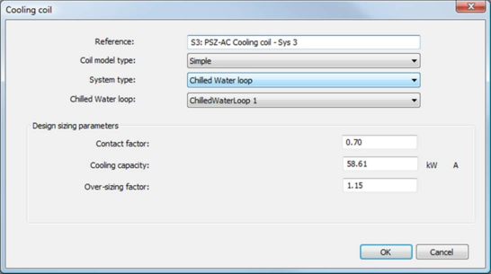
Figure 4 - 10 : Simple cooling coil model dialog with coil served by chilled water loop
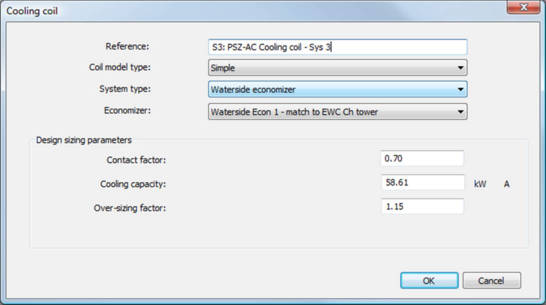
Figure 4 - 11 : Simple cooling coil dialog with coil served by a dedicated waterside economizer (this is distinct from the Integrated WSE mode available for chiller sets including water-cooled chillers on a chilled water loop, which can be used only with Advanced cooling coils)
Figure 4 - 12 : Simple cooling coil dialog (coil served by DX cooling)
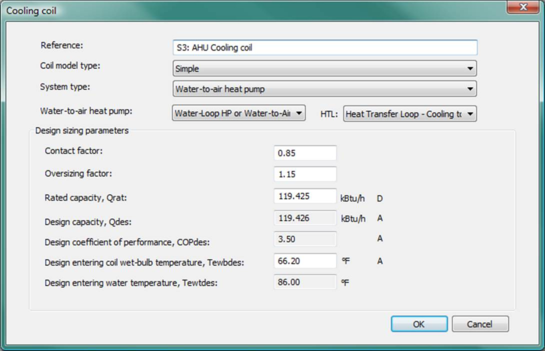
Figure 4 - 13 : Simple cooling coil dialog (coil served by Water-to-air heat pump)
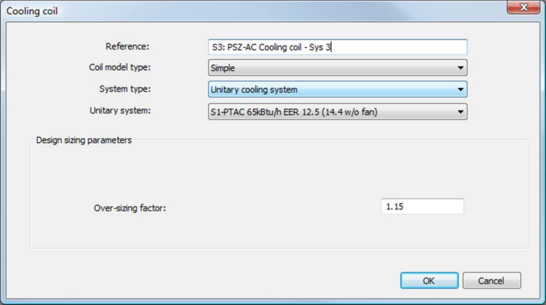
Figure 4 - 14 : Simple cooling coil model dialog (coil served by unitary cooling system)
The Advanced coil model can be selected within the Simple model dialog. Once selected, the Advanced model dialog will be the dialog for any particular coil set to use the Advanced coil model. The Advanced coil dialog is shown below for both Autosizing and Manual sizing modes.
Figure 4 - 15 : Advanced model cooling coil dialog: Autosizing mode (note that the display format setting at the bottom of the dialog allows for both modes to be shown at once, if desired).
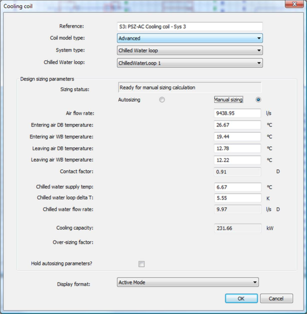
Figure 4 - 16 : Advanced model cooling coil dialog: Manual sizing mode (note that the display format setting at the bottom of the dialog allows for both modes to be shown at once, if desired).
The upper portion of both the Simple and Advanced model dialogs contain information for specifying the reference name, coil model type, and system type serving the coil. The lower section of the dialog contains the Design sizing parameters appropriate for each model type. Detailed descriptions of these parameters are provided below.
Reference
Enter a description of the component.
Coil Model type
Coil model type may be either Simple or Advanced.
System type
Select a system serving the coil from those available on the list.
System name
Select a defined system of the “System type” specified.
Design Sizing Parameters for Simple Coil Model
The following design parameters are common to a simple cooling coil served by systems other than the DX cooling and water-to-air heat pump (chilled water loop, UCS, or WSE). For a simple cooling coil served by a DX cooling or a water-to-air heat pump, there are some special parameters required by the DX cooling or water-to-air heat pump system type. Please see section 2.15.13 for details of these special parameters for a DX cooling served cooling coil. Please see section 2.9.11 for details of these special parameters for a water-to-air heat pump served cooling coil.
Coil Contact Factor (if coil served by Chilled Water Loop, Waterside economizer, or DX)
|
Default Value
|
0.91 CWL, 0.85 DX
|
|
Typical Values
|
0.70 to 0.95
|
|
Error Limits
|
0.01 to 1.0
|
The contact factor is used to describe the way air flows over the coil, and is used to calculate the balance of sensible to latent heat removal of the air passing over the coil. The contact factor specifies what proportion of the total airflow is contacted by the coil and so follows an ideal psychrometric process of cooling along a constant moisture content line until the saturation curve is met, and then following the saturation line. The balance of the airflow is assumed to be unaffected by the cooling coil but is then mixed with the cooled air upon leaving the coil.
Typical values of contact factor are in the range 0.7 - 0.95. For a given flow rate, higher contact factors will tend to be associated with coils that either have more rows of fins or a larger face area, and thus lower face velocity. A higher contact factor has the advantage of achieving the desired leaving air temperature (LAT) with relatively warmer water from the chiller. As the contact factor is reduced, the required coil temperature, and thus also water temperature, is lower, which has implications for chiller operating efficiency and chilled-water reset controls. On the other hand, a low contact factor also has the same effect as intentionally bypassing some of the air around the coil so that the cooling coil can be operated at a very low temperature for maximum dehumidification, and then mixing the bypass fraction with the very dry air off the coil to get a final LAT. While the bypass air is obviously also more humid, the net result will be a lower leaving wet-bulb temperature (WBT) for the same dry-bulb LAT—i.e., greater wet-bulb depression. This can be readily seen in ApacheHVAC system simulation results for higher and lower cooling coil contact factors in a humid climate.
Cooling capacity (if coil served by Chilled water loop, waterside economizer, or DX)
|
Default Values
|
200.00 kW
|
682.43 kBtu/h
|
|
Typical Range
|
0.50 to 250.00 kW
|
1.71 to 853.04 kBtu/h
|
|
Error Limits
|
0.05 to 1000.00 kW
|
0.17 to 3412.14 kBtu/h
|
Enter the maximum duty of the cooling coils. The simulation will limit the output from the coil to this maximum capacity, even if the controls are calling for more. In cases where there is no proportional control, the output device will be set to this value whenever the on/off control of the coil is on.
Over-sizing factor (all system types)
Specify the factor by which the cooling coil capacity is increased relative to the peak calculated value.
|
Default Values
|
1.15
|
|
Typical Range
|
1.00 to 1.50
|
|
Error Limits
|
0.00 to 5.00
|
Unitary system (if coil served by unitary cooling system)
When a unitary cooling system model is assigned to the cooling coil, this model includes a supply fan downstream of the cooling coil that is not shown on the schematic. The parameters of this fan are defined in the properties of the unitary cooling system. See Unitary Cooling Systems section.
Design Sizing Parameters for Advanced Coil Model
Sizing status
The Sizing status message box provides information on the state of the coil sizing process. This includes error messages for out-of-range or inconsistent design parameters. A summary of the Sizing status messages is provided below.
|
Cooling Coil – Advanced Model
Design/Sizing Status Summary
|
|
Sizing Mode
|
|
Autosizing
|
Manual
|
|
Status
|
Comment (full text)
|
Status
|
Comment (full text)
|
|
Ready for Autosizing
|
Required input values have been entered.
|
Ready for Manual Sizing
|
Required input values have been entered.
|
|
Autosizing complete
|
Coil has been sized using autosized parameters.
|
Calculation successful
|
Coil has been sized with input values.
|
|
Not Possible: Entering WBT too low
|
Entering air WB temperature is too low for the corresponding entering DB temperature.
|
Not Possible: Entering WBT too low
|
Entering air WB temperature is too low for the corresponding entering DB temperature
|
|
|
|
Not Possible: Leaving WBT too low
|
Leaving air WB temperature is too low for the corresponding leaving DB temperature
|
|
Not Possible: Entering WBT > Entering DBT
|
Entering air WB temperature is greater than the entering air DB temperature.
|
Not Possible: Entering WBT > Entering DBT
|
Entering air WB temperature is greater than the entering air DB temperature.
|
|
|
|
Not Possible: Leaving WBT > Leaving DBT
|
Leaving air WB temperature is greater than the leaving air DB temperature.
|
|
Not Possible: Entering DBT < Leaving CWL temperature
|
Entering air DB temperature is lower than the leaving Chilled Water Loop temperature.
|
Not Possible: Entering DBT < Leaving CWL temperature
|
Entering air DB temperature is lower than the leaving Chilled Water Loop temperature.
|
|
Not Possible: Leaving DBT < Entering CWL temperature
|
Leaving air DB temperature is lower than the entering Chilled Water Loop temperature.
|
Not Possible: Leaving DBT < Entering CWL temperature
|
Leaving air DB temperature lower than the entering Chilled Water Loop temperature.
|
|
Not Possible: Conditions not consistent with input Contact factor
|
The input airside conditions will not yield a cooling process consistent with the input Contact factor.
|
Not Possible: Conditions not feasible for cooling only process
|
The input airside conditions are not feasible for a cooling only process, i.e., the exiting air would have to be heated to reach the desired combination of DBT/WBT.
|
Air flow rate
Air flow rate is the volumetric air flow entering the coil. Air flow rate must be specified in both Autosizing/Manual modes. In Autozing mode, peak air flow rate can be determined by the System Sizing process. When an autosized air flow rate is displayed, the value will be indicated in green with a “A.” However, air flow rate still be edited from the autosized values (the value will return to black with corresponding “A”). Note that this air flow rate is only used in for determining the coil heat transfer parameters and not used by any flow controllers associated with the HVAC system on which the coil resides.
|
Default Values
|
9438.95 l/s
|
20000.00 CFM
|
|
Typical Range
|
94.39 to 14158.42 l/s
|
200 to 30000 CFM
|
|
Error Limits
|
0.00 to 474500.00 l/s
|
0.00 to 1,000,000.00 CFM
|
Entering air dry (DB) and wet-bulb (WB) temperatures
Entering air dry (DB) and wet-bulb (WB) temperatures are the air stream conditions entering the coil. These temperatures must be specified in both Autosizing/Manual modes. In Autozing mode, peak design values for these temperatures can be determined by the System Sizing process. When autosized temperatures are displayed, the value will be indicated in green with a “A.” However, the temperatures can still be edited from the autosized values (the values will return to black with corresponding “A”).
|
Default Values
|
26.67 ° C
|
80.00 ° F
|
|
Typical Range
|
15.00 to 50.00 ° C
|
60.00 to 120.00 ° F
|
|
Error Limits
|
0.00 to 100.00 ° C
|
32.00 to 212.00 ° F
|
Leaving air dry (DB) and wet-bulb (WB) temperatures
Leaving air dry (DB) and wet-bulb (WB) temperatures are the conditions of the air steam exiting the coil. Leaving air DB temperature must be specified in both Autosizing/Manual modes. In Autosizing mode, required leaving air DB temperature to meet the system load can be determined by the System Sizing process. When an autosized temperature is displayed, the value will be indicated in green with a “A.” However, the temperature can still be edited from the autosized values (the values will return to black with corresponding “A”).
In Autosize mode, the leaving air WB temperature is calculated from other entered parameters (i..e., Contact factor) and non-editable. In Manual mode, leaving air WB temperature must be specified.
|
Default Values
|
19.44 ° C
|
67.00 ° F
|
|
Typical Range
|
5.00 to 40.00 ° C
|
40.00 to 100.00 ° F
|
|
Error Limits
|
0.00 to 100.00 ° C
|
32.00 to 212.00 ° F
|
Coil Contact Factor
The coil Contact factor is as described in Section 2.10.3.5. In Autosizing mode, Contact factor is a user input. In Manual mode, Contact factor is calculated from the specified airside parameters. In Manual mode, if the user specifies a set of airside parameters that require a process not achievable by cooling alone (i.e., reheat would be needed to achieve the air leaving conditions), the Contact factor will indicated as “Not Feasible.”
|
Default Value
|
0.91
|
|
Typical Values
|
0.70 to 0.95
|
|
Error Limits
|
0.01 to 1.0
|
Chilled water loop supply temperature
Chilled water loop supply temperature is the design chilled water temperature entering the coil. In Autosize mode, this value is linked to the corresponding Chilled water loop supply temperature (see CWL section xxx) serving the coil and non-editable. In Manual mode, this value is editable, however, the edited value is local to the cooling coil and does not affect the corresponding Chilled water loop specified value.
|
Default Values
|
6.67 ° C
|
44.00 ° F
|
|
Typical Range
|
2.00 to 18.00 ° C
|
34.00 to 62.00 ° F
|
|
Error Limits
|
0.00 to 100.00 ° C
|
32.00 to 212.00 ° F
|
Chilled water loop delta temperature
Chilled water loop supply delta temperature is the design chilled water temperature rise through the coil. In Autosize mode, this value is linked to the corresponding Chilled water loop delta temperature (see Chilled Water Loop section 2.4.10) serving the coil and non-editable. In Manual mode, this value is editable, however, the edited value is local to the cooling coil and does not affect the corresponding Chilled water loop specified value.
|
Default Values
|
6.67 ° K
|
12.00 ° F
|
|
Typical Range
|
4.00 to 8.00 ° K
|
8.00 to 14.00 ° F
|
|
Error Limits
|
0.00 to 16.67 ° K
|
0.00 to 30.00 ° F
|
Chilled water loop flow rate
Chilled water loop flow rate is the design chilled water flow rate serving the coil. This value is calculated from the other coil design sizing parameters. Note that this value is adjusted by the Over-sizing factor specified. In the simulation, the necessary chilled water flow rate is determined by the coil model to meet the relevant control requirements. However, the simulation will limit the chilled water flow rate to the coil at this value even if the associated control requirements are greater.
Cooling capacity
Cooling capacity is the design heat transfer capacity of the coil. This value is calculated from the other coil design sizing parameters. Note that this value is adjusted by the Over-sizing factor specified.
Oversizing factor
The factor by which the coil design values chilled water flow rate and cooling capacity are increased relative to the autosized values. Airside parameters (flow rate, entering air DB temperature, entering air WB temperature, leaving air DB temperature, and leaving air WB temperature) are NOT adjusted by the over-sizing factor.
The coil design heat transfer with the over-sizing factor is:
The over-sizing factor is only pertinent to the Autosizing mode to allow the user to oversize the coil from an autosized design values. For the Manual sizing mode, no over-sizing factor is necessary since the coil design parameters can be set directly to consider additional capacity if desired.
|
Default Values
|
1.15
|
|
Typical Range
|
1.00 to 1.50
|
|
Error Limits
|
0.00 to 5.00
|
Hold Autosizing Parameters?
The “Hold autosizing parameters?” tick box is provided so that when switching between Autosizing and Manual sizing modes, the current set of autosized values can be held for later use.
Advanced Model Design Parameters Summary
The Advanced model design parameters for Autosize and Manual sizing modes are summarized below.
|
Cooling Coil – Advanced Model
Design Parameters Summary
|
|
Coil Design Parameter
|
Sizing Mode
|
|
Autosizing
|
Manual
|
|
Status
|
Comment
|
Status
|
Comment
|
|
Air flow rate
|
Autosized Value
Editable
|
Editable before/after System Sizing
|
User Input
Editable
|
|
|
Entering air DB temperature
|
Autosized Value
Editable
|
Editable before/after System Sizing
Dialogue will check for errors and consistency
|
User Input
Editable
|
Dialogue will check for errors and consistency
|
|
Entering air WB temperature
|
Autosized Value
Editable
|
User Input
Editable
|
|
Leaving air DB temperature
|
Autosized Value
Editable
|
User Input
Editable
|
|
Leaving air WB temperature
|
Derived Value
Non Editable
|
|
User Input
Editable
|
|
Contact factor
|
User Input
Editable
|
Dialogue will check for errors and consistency
|
Derived Value
Non-editable
|
|
|
Chilled water supply temperature
|
From CWL
Non Editable
|
|
User Input
Editable
|
Editable but edits are limited to the coil model only, i.e., do not alter the CWL values entered in the CWL dialog. Dialogue will check for errors and consistency
|
|
Chilled water loop delta T
|
From CWL
Non Editable
|
|
User Input
Editable
|
|
Chilled water flow rate
|
Derived Value
Non Editable
|
|
Derived Value
Non Editable
|
|
|
Cooling capacity
|
Derived Value
Non Editable
|
|
Derived Value
Non Editable
|
|
|
Over-sizing factor
|
User Input
Editable
|
|
User Input
Editable
|
|
|
Hold autosizing parameters?
|
User Selected
|
Autosized parameters will be “held” as the user switches between Autosize and Manual sizing modes.
|
Not Applicable
|