Toolbar buttons for placement of “T” Junction components
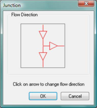
Junction component after placement, but before flow directions have been set.
Convergent and divergent junction components (flow direction have been set).
Figure 4 - 26 : Clicking on the red arrows in the Junction flow direction dialog determines the direction of flow on each branch and thus also the divergent versus convergent nature of the junction component. Percentage flow control can be used on one branch only in the case of divergent junctions.
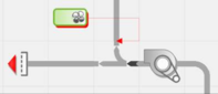
When the flows for a junction component are set to be divergent, the junction can be controlled to function as a fixed or variable percentage-flow splitter damper. Until a percentage flow controller is pointed to the downstream node at one of two outlets on a divergent junction, it functions as a simple uncontrolled junction of airflow paths. Attaching a percentage flow controller to either one of the two outlets provides a controlled split of the flow, regardless of the current flow rate. It is important the percentage-flow control is applied to only one of the two downstream nodes, and not both. Currently (as of VE 2012) controlled divergent junctions are limited to applications for which the flow rate on the inlet branch is determined upstream of the junction. Furthermore, the flow must not also be determined by a flow-rate controller on the same downstream branch as the percentage flow controller, as this would create an over-constrained path. See also Appendix A: Rules for Air Flow Specification.
Figure 4 - 27 : Divergent junction with percentage flow controller attached to one of two outlets.

 Junction component after placement, but before flow directions have been set.
 Convergent and divergent junction components (flow direction have been set).