Direct-expansion or ‘DX’ cooling is modeled by defining a DX cooling type serving a simple cooling coil with its System type within the coil dialog selected as DX cooling.
Starting from VE2012 (v6.5), the ‘shape’ and ‘size’ of the DX cooling performance characteristic have been separated. Therefore, the DX cooling needs to be defined in two levels:
· Parameters correspond to the shape of the DX cooling performance are defined in the DX cooling ‘type’ level (the DX cooling dialog).
· Parameters correspond to the size of the DX cooling performance are defined in the DX cooling ‘instance’ level (the DX Cooling variant of the simple cooling coil dialog).
DX Cooling model
The DX cooling model simulates the refrigerant side of a DX cooling system. The DX cooling airside (the cooling coil or evaporator) is modeled with a version of the current ApacheHVAC simple cooling coil model dedicated to DX cooling, using the total available DX cooling capacity calculated by the DX cooling model. This model uses default or user-defined DX cooling performance characteristics at rated conditions and three performance curves to determine DX cooling performance at off-rated conditions.
The three DX cooling performance curves are:
· DX cooling capacity (temperature dependence) curve
· DX cooling electric input ratio (EIR) (temp dependence) curve
· DX cooling electric input ratio (EIR) (part-load dependence) curve
The DX cooling model includes the compressor and outdoor (condenser) fan power and thus energy consumption. If the condenser type is set to be evaporatively cooled, the DX Cooling model also accounts for spray pump power and energy consumption. It does not include the indoor (supply) fan power. Supply fans for DX cooling systems must be modeled separately as an ApacheHVAC fan component (see discussion below of this with respect to ASHRAE standard EER values under Pre-defined DX Cooling types).
The DX cooling model covers both air-cooled and evaporative-cooled condensers. Energy consumption by condenser fans (and spray pumps if evaporative-cooled) is included in the DX units’ Electric Input Ratio (EIR) and associated performance curves. A condenser fan (and spray pump when the evaporatively cooled condenser option is selected) Electric Input Ratio (EIRfan/pump), representing the ratio of condenser fan power consumption to the total DX unit power consumption, is used to split the calculated energy consumption into separate results for compressor vs. condenser fan (and spray pump when included).
DX cooling model description
The following information can be accessed via the DX Cooling model description button in the DX Cooling dialog. It describes the variables and some of the fundamental relationships in the DX Cooling model.
· Rated cooling capacity: Qrat
· Rated coefficient of performance: COPrat
· Entering coil wet bulb temperature: Tewb
· Entering condenser temperature*: Tect
· Variable cooling capacity: Qcap = Qrat fCAPtt (Tewb and Tect)
· Cooling load: Q
· Part-load ratio: p = Q/Qcap
· DX cooling Electric Input Ratio: EIR = fEIRtt(Tewb and Tect) fEIRp(p) / (p COPrat)
· Total DX cooling power, including compressor and condenser fan (& pump) power: W = EIR Q
· Condenser fan (and spray pump when evaporatively cooled) Electric Input Ratio: EIR fan/pump
· Condenser fan/pump power: W fan/pump = EIR fan/pump W
· Compressor power: Wcpr = W – W fan/pump
*Equals outdoor air dry-bulb temperature Todb when condenser type is air-cooled; Equals outdoor air wet-bulb temperature Towb when condenser type is evaporative-cooled.
One-to-one relationship of DX Cooling model type and coil
As DX Cooling is a type, each connected coil generates another copy or instance of the selected type at the time of simulation. The performance curves in the type dialog are scaled for each instance in keeping with the Rated capacity in the coil dialog.
DX Cooling COP and condenser fan power
The COP in an ApacheHVAC DX Cooling accounts for the total energy consumption of the DX cooling unit as a component in ApacheHVAC. DX Cooling inputs for COP and condenser fan power assume that the condenser fan is included performance curves—i.e., the condenser fan power is always a fraction of the total power required, and that total is determined by the COP at rated condition and the performance curves. The EIR for the condenser fan (and spray pump if evaporatively cooled condenser) determine what fraction of the power is used for condenser heat rejection. Only the supply/distribution fan is excluded from the DX Cooling power.
For example, if, when working in metric units, you had a DX cooling system with capacity of 3.0 kW and COP of 3.0 at the rated conditions, then for that output at those conditions the unit, with condenser fan, will use 1.0 kW. If the condenser fan power is 50 W, with a calculated EIR of 0.05, then 50 W or 5% of the 1.0 kW total will be allocated to the condenser fan. As the condenser fan EIR does not change the COP or the performance curve and does not add to the total power used, this is really only for the benefit of determining the split between energy consumption for cooling vs. heat rejection.
Rated condition and Design condition
The rated condition is the basis for the calculation of DX cooling performance at simulation time. The rated condition is normally the ARI rating condition or equivalent in locations where other equipment rating standards apply—i.e., this is the condition at which the DX unit characteristics are specified by a manufacturer. However, it can optionally be the design condition.
The default rated condition data are based on the standard ARI conditions ( ARI Standard 340/360-2007 and ARI Standard 210/240-2008 ). These include the following:
· Outdoor (condenser) section entering air:
o dry-bulb temperature 95 oF (35 oC)
o wet-bulb temperature 75 oF (23.9 oC)
· Indoor (evaporator) section entering air :
o dry-bulb temperature 80 o F (26.7 o C)
o wet-bulb temperature 67 o F (19.4 o C)
The design condition, on the other hand, is the condition at the time of peak design cooling load.
Except for rated capacity, rated condition data should be entered or edited on the DX cooling ‘type’ level, in the Rated condition tab of the DX cooling dialog.
Design condition data, together with rated capacity, should be entered or edited on the DX cooling ‘instance’ level, in the simple cooling coil dialog with the ‘System type’ selected as DX cooling.
To use catalogue DX cooling data, enter a cooling capacity and COP at the rated condition and read the derived capacity and COP at the design condition.
Under normal conditions, Design cooling capacity and COP in the simple cooling coil dialog are derived based upon the following parameters:
· Selected DX cooling performance curves (from the DX cooling type)
· Rated Cooling capacity (from the DX cooling instance)
· Rated COP (from the DX cooling type)
· Rated Condenser: Outdoor air dry-bulb (wet-bulb) temperature (from the DX cooling type)
· Rated Evaporator: Entering air wet-bulb temperature (from the DX cooling type)
· Design Condenser: Outdoor air dry-bulb (wet-bulb) temperature (from the DX cooling instance)
· Design Evaporator: Entering air wet-bulb temperature (from the DX cooling instance)
In the special case of updating parameters for the simple cooling coils served by DX cooling after autosizing, design cooling capacity, and design outdoor air dry-bulb (or wet-bulb) temperature and Design entering air wet-bulb temperature, are firstly updated with the autosized DX cooling coil capacity, and the outdoor air dry-bulb (or wet-bulb) temperature and entering air wet-bulb temperature values accompanying the autosized capacity. Rated capacity and Design COP are then derived using the updated design capacity, and the updated design outdoor air dry-bulb (or wet-bulb) temperature and design entering air wet-bulb temperature, together with performance curves and other rated parameters that are not updated by the autosizing process.
DX cooling sizing procedure
As the DX cooling data correspond to the ‘size’ of the DX cooling unit are defined and stored on the ‘instance’ level (in the cooling coil dialog), only the instance level (size) parameters need to be updated during system sizing. Therefore, DX cooling instance sizing is covered by the normal sizing process for its connected simple cooling coil. No additional sizing process is needed for the DX cooling types.
When updating parameters for the simple cooling coils served by DX cooling after autosizing, design cooling capacity, and design outdoor air dry-bulb (or wet-bulb) temperature and Design entering air wet-bulb temperature, are firstly updated with the autosized DX cooling coil capacity, and the outdoor air dry-bulb (or wet-bulb) temperature and entering air wet-bulb temperature values accompanying the autosized capacity. Rated capacity and Design COP are then derived using the updated design capacity, and the updated design outdoor air dry-bulb (or wet-bulb) temperature and design entering air wet-bulb temperature, together with performance curves and other rated parameters that are not updated by the autosizing process.
DX cooling type level data
The DX cooling ‘type’ level parameters are accessed through the DX cooling (types) dialog and the DX cooling dialog. These parameters determine the ‘shape’ (non-size-related) performance characteristics of a DX cooling unit, independent of its cooling capacity.
DX cooling (types) dialog
The DX cooling ‘type’ level parameters are accessed through the DX cooling (types) tool, which facilitates adding, editing, copying and removing named DX cooling types.
DX cooling types are accessed through the toolbar button shown below.

Toolbar button for DX Cooling (types) list.
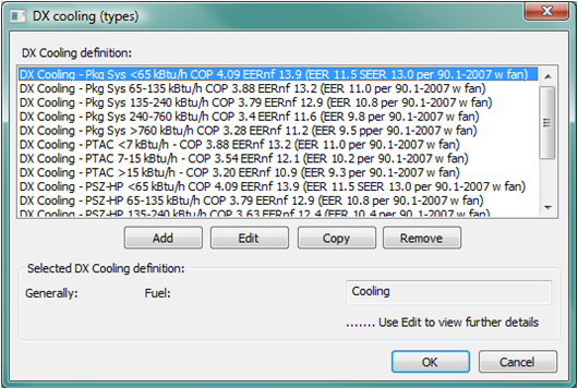
This facility supports defining the performance characteristics of one or more DX cooling types. Clicking this toolbar button opens up the ‘DX cooling (types)’ dialog (shown below), which manages a set of DX cooling types. A DX cooling type may be added, edited, copied or removed through the corresponding buttons in this dialog. Double clicking on an existing DX cooling type (or clicking the ‘Edit’ button after selection of an existing DX cooling type) opens up the ‘DX cooling’ dialog (shown below), where parameters for a DX cooling type may be edited.
Figure 3 - 121 : DX Cooling Types dialog
The entities defined here are types. A single DX cooling type defining fundamental performance characteristics may be assigned to many cooling coils. A separate instance of the assigned type is automatically created for each cooling coil. This provides a one-to-one relationship between modeled DX cooling “types” and connected DX coils. The contact factor, capacity, and design conditions can then be autosized and/or edited for each instance via the coil dialog. In this respect, DX cooling components differ significantly from chillers.
Pre-defined DX Cooling Types
There are 15 pre-defined DX Cooling types, and users can replace, copy, and or edit any of these:
· 9 for Packaged Air-Conditioning systems and Packaged single-zone heat pumps (PSZ-HP)
· 6 for Packaged Terminal Air-Conditioning (PTAC) Packaged Terminal Heat Pumps (PTHP)
These pre-defined systems differ in terms of size ranges and associated COPs. The COP values in the pre-defined DX Cooling types match ASHRAE 90.1-2007 requirements (according to the tables at the end of Chapter 6), as adjusted per CA Title-24 ACM Manual methods to remove the supply fan power from the EER that was determined for a packaged unit at ARI conditions. For reference, the EER with SA fan power include (i.e., straight from 90.1-2007 chapter 6) and the intermediate value EERnf (EER with no fan, per the Title-24 ACM Manual calculation) are included in the name of each type. EERnf is then converted to COP without the fan, which is the input used in the DX Cooling dialog.
DX Cooling dialog
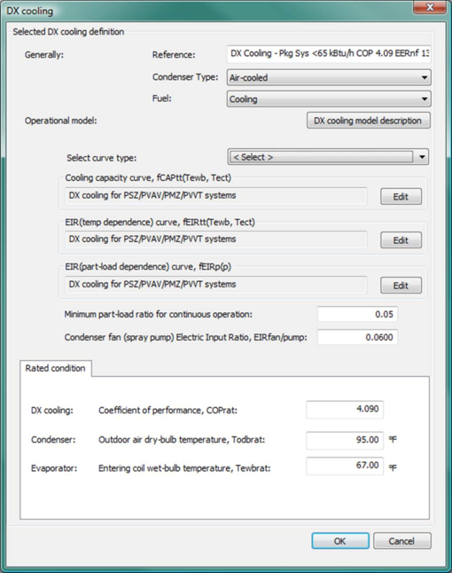
Figure 3 - 122 : DX Cooling edit dialog .
The DX cooling dialog contains the ‘type’ level parameters for a DX cooling unit. It provides editing access to the parameters that determine the ‘shape’ characteristics of the performance.
Reference name
Enter a descriptive name for the DX Cooling type. The reference is for your use when referencing the current DX Cooling type within component and controller dialogs. These references can be valuable in organizing and navigating the system and when the system model is later re-used on another project or passed on to another modeler. Reference names should thus be informative with respect to differentiating similar equipment, components, and controllers.
Condenser type
Select either air-cooled (dry) or Evaporatively cooled. This automatically changes the available pre-defined performance curves and adds or removes the evaporative cooling spray pump component from the model. The differences here are further described in the DX Cooling Model section above.
Fuel
Select the “fuel” or energy source used by the DX Cooling type to determine the category for reporting energy consumption results. For scratch-built system models, this should normally be set to “Electricity”. It will be pre-set to “Cooling” as an Energy end-use category consistent with LEED EA credit 1 submittal requirements for the pre-defined prototype ApacheHVAC systems, as provided by the Prototype Systems Library, System Prototypes & Sizing facility, and the ASHRAE 90.1 PRM workflow navigator.
Operational model: DX Cooling Model Description
Click the DX Cooling model description button or see DX Cooling model and DX cooling model description above for description of model variables and fundamental relationships.
Minimum part-load ratio for continuous operation
Enter the part-load ratio (fraction of 1.0) below which the compressor should cycle on/off to meet the load rather than operate continuously.
Condenser fan (spray pump) Electric Input Ratio
Enter the Electric Input Ratio (EIR) of the condenser fan (and spray pump when included), as a fraction of the overall electric power input required for the DX Cooling equipment at the rated cooling capacity and rated condition. If the condenser is evaporatively cooled, the EIR value should also include the spray pump power fraction. The condenser fan power (and spray pump power when included) is typically the maximum value for these parasitic loads.
Because the Cooling capacity and COP at Rated condition, as reported by the manufacturer, normally include the condenser fan (and spray pump) power, the condenser fan (and spray pump) power is modeled as a fraction of the overall energy consumption of the DX Cooling equipment, see the DX Cooling Model section above. The EIR is used at each simulation time step to determine the condenser fan/spray pump power as a fraction of the overall energy consumption of the DX Cooling equipment at any particular part-load condition.
Performance curves
DX Cooling performance curves are selected or edited on the DX Cooling ‘type’ level, in the DX Cooling dialog. There are three performance curves required, one for capacity and two for energy consumption.
Performance curve selection
Performance curves for a specific DX cooling type are selected through the Select curve type (< Select >) dropdown list. Selecting a particular curve type from this single combo box populates the same curve name into each of the three curve boxes below, and the corresponding three curves are selected for the DX cooling type.
Cooling capacity curve
Using the drop-down <Select> menu, choose the most appropriate pre-defined Cooling capacity performance curve for the type of system you are modeling. The available choices for this will be constrained by the selection of Air-cooled vs. Evaporatively cooled condenser type (above).
Advanced users: The Edit button provides access to editing the performance curve coefficients and other associated performance parameters. A separate section on DX Cooling Performance curves details and editing is provided below.
EIR temperature dependence curve
Using the drop-down <Select> menu, choose the most appropriate pre-defined temperature dependence performance curve for the type of system you are modeling. The available choices for this will be constrained by the selection of Air-cooled vs. Evaporatively cooled condenser type (above).
Advanced users: The Edit button provides access to editing the performance curve coefficients and other associated performance parameters. A separate section on DX Cooling Performance curves details and editing is provided below.
EIR part-load dependence curve
Using the drop-down <Select> menu, choose the most appropriate pre-defined part-load dependence performance curve for the type of system you are modeling. The available choices for this will be constrained by the selection of Air-cooled vs. Evaporatively cooled condenser type (above).
Advanced users: The Edit button provides access to editing the performance curve coefficients and other associated performance parameters. A separate section on DX Cooling Performance curves details and editing is provided below.
Rated condition
Except for rated capacity, rated condition data are entered or edited on the DX cooling ‘type’ level, in the Rated condition tab of the DX cooling dialog.
Rated Coefficient of performance (COP)
Enter the COP at the Rated condition. This is the ratio of cooling capacity to the electric energy required, including compressor and condenser fan (plus spray pump, if any), to provide this cooling output at the rated condition. This value is used both in simulation and to calculate COP at the Design condition.
Rated Condenser: Outdoor air dry-bulb (wet-bulb) temperature
Enter the Outdoor air dry-bulb temperature as seen by the condenser at the rated condition. If the condenser is evaporatively cooled, enter the Outdoor air wet-bulb temperature at the rated condition.
Rated Evaporator: Entering air wet-bulb temperature
Enter the Entering air wet-bulb temperature seen by the evaporator coil at the rated condition.
DX cooling instance level data
The DX cooling ‘instance’ level parameters are accessed through the DX cooling served simple cooling coils. These parameters determine the size of the performance characteristics of a DX cooling unit, and can be edited in the simple cooling coil dialog, which has a System type selected as DX cooling.
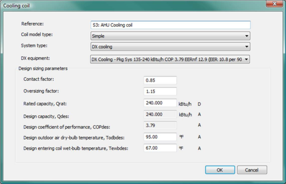
Figure 3 - 123 : Simple cooling coil dialog (shown with System type selected as DX cooling)
DX cooling data in the cooling coil dialog
DX cooling ‘instance’ level parameters are provided in the cooling coil dialog when the System type is set to DX cooling.
In addition to the parameters for Contact factor and Oversizing factor, which are common to simple cooling coils served by other system types (chilled water loop, water-to-air-heat pumps, etc.), a simple cooling coil served by DX cooling has the following special parameters required by the DX cooling system type (See section 2.18 Cooling coils for information regarding these common coil parameters).
DX equipment
Select the DX cooling type that is used to serve this simple cooling coil, from the DX equipment dropdown list, which will list all DX cooling types that have been defined in the system. The DX cooling type determines the shape of the performance characteristics of a DX cooling unit.
Rated capacity, Qrat
Enter the cooling capacity at the Rated condition. This value is used both in simulation and to calculate cooling capacity at the Design condition. This parameter is autosizable. When this parameter is autosized, its value in the field and its autosizing label ‘A’ becomes green.
Design capacity, Qdes
Normally, design cooling capacity is automatically derived using performance curves and rated parameters for the selected DX cooling type and other rated and design parameters provided in this dialog.
In the special case of updating parameters for the simple cooling coils served by DX cooling after autosizing, design cooling capacity, and design outdoor air dry-bulb (or wet-bulb) temperature and Design entering air wet-bulb temperature, are firstly updated with the autosized DX cooling coil capacity, and the outdoor air dry-bulb (or wet-bulb) temperature and entering air wet-bulb temperature values accompanying the autosized capacity. Rated capacity and Design COP are then derived using the updated design capacity, and the updated design outdoor air dry-bulb (or wet-bulb) temperature and design entering air wet-bulb temperature, together with performance curves and other rated parameters that are not updated by the autosizing process.
This parameter is autosizable. When this parameter is autosized, its value in the field and its autosizing label ‘A’ becomes green.
Design coefficient of performance, COPdes
Design coefficient of performance (COP) is the ratio of design cooling capacity to the electric energy required, including compressor and condenser fan (plus spray pump, if any), to provide this cooling output at the design condition. This value is automatically derived using performance curves and rated parameters for the selected DX cooling type and other rated and design parameters provided in this dialog.
This parameter is autosizable. When this parameter is autosized, its value in the field and its autosizing label ‘A’ becomes green.
Design Outdoor air dry-bulb (wet-bulb) temperature
Enter the Outdoor air dry-bulb temperature seen by the condenser at the Design condition. If the condenser is evaporatively cooled, enter the Outdoor air wet-bulb temperature at the Design condition.
This parameter is autosizable. When this parameter is autosized, its value in the field and its autosizing label ‘A’ becomes green.
Design Entering air wet-bulb temperature
Enter the Entering air wet-bulb temperature seen by the evaporator coil at the Design condition.
This parameter is autosizable. When this parameter is autosized, its value in the field and its autosizing label ‘A’ becomes green.
DX Cooling Performance curves: details and editing
Cooling Capacity curve, fCAPtt(Tewb,Tect), details and editing
Use the Edit button to view and edit the curve parameters. The Curve Editing dialog displays the formula and parameters of the curve and provides for editing of the curve parameters. You are permitted to edit the curve coefficients and the applicable ranges of the independent variables.
When editing the curve parameters, it is important that you understand the meaning of the curve and its usage in the model algorithm.
Ensure that the edited curve has reasonable ranges for the independent variables. A performance curve is valid only within its applicable ranges. If the independent variables are outside of the ranges that you set, the specified variable limits (maximum or minimum values) will be used.
Figure 3 - 124 : Edit dialog for the cooling capacity curve of DX cooling type
The cooling capacity curve f CAPtt (T ewb, T ect ) is a bi-quadratic function of
tewb = T ewb – Tdatum
tect = T ect – Tdatum
where
T ewb = entering coil wet bulb temperature.
T ect = entering condenser temperature. It equals outdoor air dry-bulb temperature Todb when condenser type is air-cooled; or equals outdoor air wet-bulb temperature Towb when condenser type is evaporative-cooled.
T datum = datum temperature (0°C or 0°F), introduced for the convenience of units conversion of the curve coefficients.
And:
fCAPtt(T ewb , T ect ) = (C00 + C10 tewb + C20 tewb 2 + C01 tect + C02 tect 2 + C11 tewb tect) / Cnorm
where
C 00 , C 10 , C 20 , C 01 , C 02 and C 11 are the curve coefficients
C norm is adjusted (by the program) to make f CAPtt (T ewbrat, T ectrat ) = 1
T ectrat = rated entering condenser temperature.
T ewbrat = rated entering coil wet bulb temperature.
The cooling capacity curve is evaluated at each time step during the simulation. The curve value is multiplied by the rated cooling capacity (Q rat ) to get the available (full-load) cooling capacity (Q cap ) of the current time step, for the specific T ewb and T ect temperatures:
Qcap = Qrat fCAPtt(T ewb , T ect )
The curve should have a value of 1.0 when the temperatures are at rated conditions.
EIR Temperature Dependence curve, fEIRtt(Tewb,Tect), details and editing
Use the Edit button to view and edit the curve parameters. The Curve Editing dialog displays the formula and parameters of the curve and provides for editing of the curve parameters. You are permitted to edit the curve coefficients and the applicable ranges of the independent variables.
When editing the curve parameters, it is important that you understand the meaning of the curve and its usage in the model algorithm.
Ensure that the edited curve has reasonable ranges for the independent variables. A performance curve is valid only within its applicable ranges. If the independent variables are outside of the ranges that you set, the specified variable limits (maximum or minimum values) will be used.
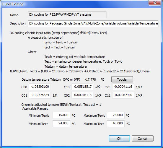
Figure 3 - 125 : Edit dialog for the EIR temperature dependence curve of DX cooling type
The DX cooling EIR (temperature dependence) curve f EIRtt (T ewb , T ect ) is a bi-quadratic function of
tewb = T ewb – Tdatum
tect = T ect – Tdatum
where
T ewb = entering coil wet bulb temperature.
T ect = entering condenser temperature. It equals outdoor air dry-bulb temperature Todb when condenser type is air-cooled; or equals outdoor air wet-bulb temperature Towb when condenser type is evaporative-cooled.
T datum = datum temperature (0°C or 0°F), introduced for the convenience of units conversion of the curve coefficients.
And:
fEIRtt(T ewb , T ect ) = (C00 + C10 tewb + C20 tewb 2 + C01 tect + C02 tect 2 + C11 tewb tect) / Cnorm
where
C 00 , C 10 , C 20 , C 01 , C 02 and C 11 are the curve coefficients
C norm is adjusted (by the program) to make f EIRtt (T ewbrat, T ectrat ) = 1
T ectrat = rated entering condenser temperature.
T ewbrat = rated entering coil wet bulb temperature.
The DX cooling EIR (temperature dependence) curve is evaluated at each time step during the simulation. The curve value is multiplied by the rated EIR (= 1/ COP rat , where COP rat is the rated coefficient of performance) to get the full-load EIR of the current time step, for the specific T ewb and T ect temperatures. The curve should have a value of 1.0 when the temperatures are at rated conditions.
EIR Part-load Dependence curve, fEIRp(p), details and editing
Use the Edit button to view and edit the curve parameters. The Curve Editing dialog displays the formula and parameters of the curve and provides for editing of the curve parameters. You are permitted to edit the curve coefficients and the applicable ranges of the independent variables.
When editing the curve parameters, it is important that you understand the meaning of the curve and its usage in the model algorithm.
Ensure that the edited curve has reasonable ranges for the independent variables. A performance curve is valid only within its applicable ranges. If the independent variables are outside of the ranges that you set, the specified variable limits (maximum or minimum values) will be used.
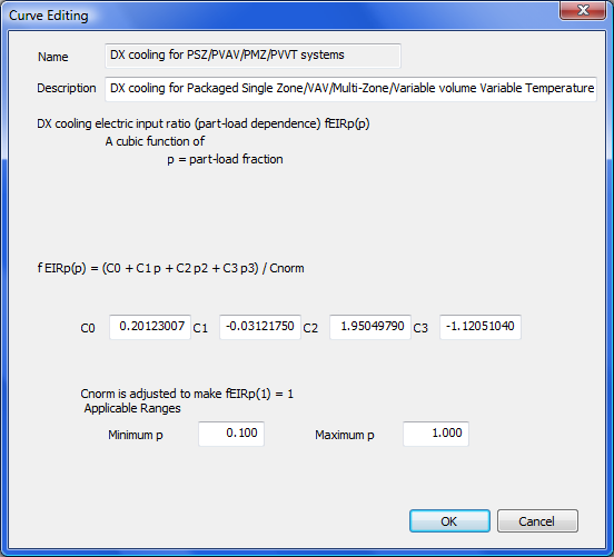
Figure 3 - 126 : Edit dialog for the EIR part-load dependence curve of DX cooling type
The DX cooling EIR (part-load dependence) curve f EIRp (p) is a bi-quadratic function of
p = Q/Q cap
where
p = part-load fraction
Q = cooling load
Q cap = available (full-load) cooling capacity
And:
f EIRp (p) = (C 0 + C 1 p + C 2 p 2 + C 3 p 3 ) / C norm
where
C 0 , C 1 , C 2 , and C 3 are the curve coefficients,
C norm is adjusted (by the program) to make f EIRp (1) = 1
The DX cooling EIR (part-load dependence) curve is evaluated at each time step during the simulation. The curve value is multiplied by the rated EIR (= 1/ COP rat , where COP rat is the rated coefficient of performance) and the EIR (temperature dependence) curve value to get the EIR of the current time step, for the specific T ewb and T ect temperatures and the specific part load ratio at which the DX cooling unit is operating:
EIR = f EIRtt (T ewb, T ect ) f EIRp (p) / (pCOP rat )
The curve should have a value of 1.0 when the part load ratio equals 1.0 and the temperatures are at rated conditions.
A note on the applicable range of part-load ratio p:
The minimum p is used by the program as the minimum unloading ratio, where the DX cooling unit capacity can no longer be reduced by normal unloading mechanism and the DX unit must be false loaded to meet smaller cooling loads. A typical false loading strategy is hot-gas bypass. If this is the false loading strategy used by the DX unit, the minimum p is the part load ratio at which hot gas bypass starts.
The maximum p should usually be 1.0. During the simulation, a part-load ratio greater than 1.0 is a sign of DX cooling units undersizing.
Unitary Cooling Systems (types)

Toolbar button for Unitary Cooling Systems (types) list.
This facility supports defining the characteristics of one or more unitary air conditioning systems.
The entities defined here are types, rather than instances. A single unitary cooling system type may be assigned to many cooling coils, and an instance of the component is automatically created for each cooling coil to which the type is assigned. In this respect unitary cooling systems differ from chillers.
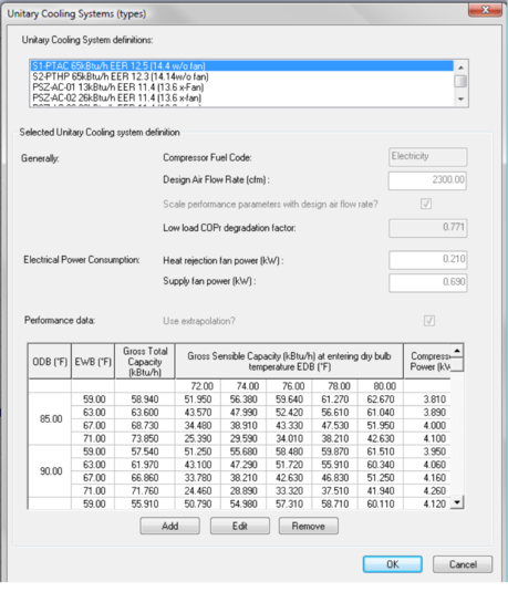
Figure 3 - 127 : Unitary cooling system (types) list
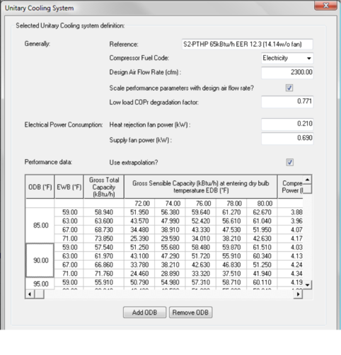
Figure 3 - 128 : Unitary cooling system (types) editing dialog.
The unitary cooling system is a unitary split vapor compression cycle cooling system serving one zone. It consists of an outdoor air-cooled condensing unit, a compressor and an indoor evaporator coil. On the outdoor side there is a heat rejection fan and on the indoor side a supply fan, which is downstream of the evaporator coil. The system does not incorporate a fresh air supply and it does not provide heating.
On the schematic a unitary cooling system should be set up by placing a cooling coil in a loop circulating air through a room and assigning a suitable unitary cooling system type to the cooling coil. The supply fan will then be placed automatically in the duct following the cooling coil, but it is not shown on the schematic.
In the intended mode of operation the compressor and both fans cycle to maintain the desired room set point. While the system is on it delivers cooling at a rate determined by the outside air dry bulb temperature and the condition of the air entering the evaporator coil. This control regime should be set up in ApacheHVAC by setting an unattainably low temperature set point for the cooling coil (for example 0˚C) and modulating the coil airflow on a proportional band in response to room temperature. The airflow through the coil will then be a time average, which is achieved in the real system by on/off cycling.
Other control regimes are possible, but deviation from the intended mode of operation may invalidate the performance map on which the algorithm depends.
The default data for this component is taken from ASHRAE 140-2004 [1], which specifies a series of tests for building energy simulation programs. The data used is from Table 26d of the standard, where the data is expressed in IP units.
Reference
Enter a description of the component. The reference is limited to 100 characters. It is for your use when selecting, organizing, and referencing any component or controllers within other component and controller dialogs and in the component browser tree. These references can be valuable in organizing and navigating the system and when the system model is later re-used on another project or passed on to another modeler. Reference names should thus be informative with respect to differentiating similar equipment, components, and controllers.
Compressor fuel code
The fuel used by the compressor. This will normally be ‘Electricity’, but other fuels, such as ‘Miscellaneous A’, may sometimes be appropriate.
Airflow rate
The flow rate through the evaporator coil under design conditions. The flow through the coil during simulation must be no greater than this. When it is less, the flow reduction is assumed to be achieved on a time average by cycling the fan operation.
Scale performance parameters with design airflow rate?
If this box is ticked any change to the design airflow rate will cause all the performance parameters expressed in power units to be scaled in proportion. This allows the performance of a similar unit of a different size to be modeled to a good approximation.
Unitary Cooling System Performance Data
This data defines a performance map describing the performance of the system under varying external and on-coil conditions. The values may be edited in the table, and the number of rows and columns may be edited using the Add and Remove buttons.
ODB
Values of outside dry bulb temperature
EWB
Values of evaporator coil entering (thermodynamic) wet bulb temperature at which the system performance is specified.
Entering dry bulb temperature
Values of evaporator coil entering dry bulb temperature at which the system performance is specified.
Gross Total Capacity
The total (sensible plus latent) cooling output of the evaporator coil when the system is operating at capacity (that is, at design supply airflow) under conditions when the evaporator coil is wet . This is referred to as gross total capacity because it is offset by the supply air fan gain. This value does not apply when the evaporator coil is dry, and in this case the gross sensible capacity is equal to the gross sensible capacity. A dry coil is indicated by the figure for gross sensible capacity being greater than the figure for gross total capacity. In general, interpolation of the performance map is required to determine whether the coil is wet or dry. This interpolation is done automatically by the simulation algorithm.
Gross Sensible Capacity
The sensible cooling output of the evaporator coil when the system is operating at capacity (design supply airflow). As with gross total capacity, the term gross is applied because the cooling effect is offset by the supply air fan gain.
Compressor Power
The power required to drive the compressor when the system is operating at capacity.
Use extrapolation?
If this box is ticked, which is the recommended setting, the program will extrapolate the performance parameters gross total capacity, gross sensible capacity and compressor power when the operating condition lies outside the bounds of the performance map. The extrapolation is applied using data from the cell of the performance map that lies closest to the operating condition. If the box is not ticked the performance parameters are set to those at the nearest point of the performance map.
Heat rejection fan power
The power consumption of the outdoor heat rejection fan. This is accounted for as system electricity.
Supply fan power
The power consumption of the indoor supply air fan. All the heat from the supply fan is assumed to enter the air stream. This is accounted for as system electricity.
Low load COPr degradation factor
At part load, when the supply fan is cycling, there is a degradation of system efficiency. This is modeled using a degradation factor applied to the refrigeration coefficient of performance, COP r , defined by
COP r = (gross total coil load) / (compressor power)
At part load, COPr is reduced by a load-dependent multiplicative COP r degradation factor, CDF:
COP r = COP rfull * CDF
where COP rfull is the value of COP r at full load (for a given outside and on-coil condition).
CDF is assumed to be a linear function of part load ratio, PLR:
CDF = CDF 0 + (1 - CDF 0 )*PLR
where PLR is defined as
PLR = (gross total coil load) / (gross total coil capacity)
and CDF 0 is a dimensionless constant with a value in the range (0,1) - the low load COPr degradation factor.
The COP r degradation factor also has an effect on fan power consumption and supply air fan gain. This effect is modeled by assuming that the COP r degradation is due to a start-up period preceding each operational period, during which the evaporator coil attains its equilibrium value and effectively contributes nothing to cooling. During this start-up period the compressor, and both the supply and heat rejection fans, are assumed to be on.