Air-to-Air Heat/Enthalpy Exchanger — Heat Recovery Devices
In order to enable a range of different device types to be modeled, a fairly simple representation of the heat recovery process has been used. This describes the sensible and latent heat recovery potential in terms of device effectiveness (see ASHRAE handbook for definition and typical values).
Heat recovery devices can be controlled only as a function of exiting dry-bulb temperature. In other words, the 'variable being controlled' must be dry-bulb temperature. For either enthalpy recovery or modeling of a desiccant dried by a heat source, see the section on Latent Heat Effectiveness below. In the latter case, a heating coil is required to properly model the drying of the desiccant, and thus the undesirable transfer of sensible heat in the direction opposite to the latent heat.
It is important also to note also that this is the one component that has two downstream nodes that can be controlled: one at the top and one at the bottom of the component. However, you must pick just one of these two airstreams for the control point.
If you require the heat recovery device to be full on, control the downstream node of the supply side to a high temperature by entering an unachievable high target temperature, such as 100, in the value for maximum control signal. If you intend to recover “coolth” from an exhaust airstream, it is generally best to do so by controlling the leaving exhaust air exit node to an unachievable high target, such that heat transfer performance will be limited only by the effectiveness parameters.

Toolbar button for placement of Air-to-Air Heat/Enthalpy Exchanger component

Air-to-Air Heat/Enthalpy Exchanger component
Reference
Enter a description of the component. The reference is limited to 100 characters. It is for your use when selecting, organizing, and referencing any component or controllers within other component and controller dialogs and in the component browser tree. These references can be valuable in organizing and navigating the system and when the system model is later re-used on another project or passed on to another modeler. Reference names should thus be informative with respect to differentiating similar equipment, components, and controllers.
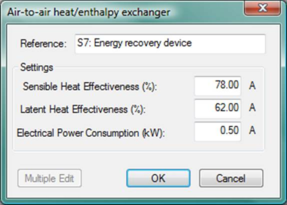
Figure 4 - 19 : Heat recovery dialog
Sensible Heat Effectiveness
Enter the sensible heat effectiveness.
|
Warning Limits (%)
|
30.0 to 90.0
|
|
Error Limits (%)
|
0.0 to 100.0
|
Latent Heat Effectiveness
Enter the latent heat effectiveness. Note that a negative latent effectiveness is permitted, but should be used only in the case of modeling a desiccant that is being actively dried or “regenerated,” thus allowing latent energy to be transferred in an “uphill” direction.
|
Warning Limits (%)
|
-60 to 90.0
|
|
Error Limits (%)
|
-100.0 to 100.0
|
Electrical Power Consumed When Operating
Enter the electrical power consumed when operating. This might be the pump power for a run-around coil, the motor power for a thermal wheel, etc.
|
Warning Limits (kW)
|
0.0 to 15.0
|
|
Error Limits (kW)
|
0.0 to 9999.0
|