Mixing & Return Air Damper Set

Toolbar button for placement of a Mixing Damper

Mixing Damper Set component on the airside HVAC network
The mixing damper controls flow from the left inlet branch as a percentage of the mixed-air flow, subject to a preset minimum. The minimum can be scheduled or modulated by a time-switch profile in the damper component dialog. A controller then modulates flow from the left branch vs. bottom branch as a percentage of the outlet flow rate or in an attempt to achieve a target mixed-air temperature. Typical applications include outside air economizers, demand-controlled ventilation, and bypass dampers for heat-recovery, indirect evaporative cooling, heat pipes, coils with high static pressure, or similar components within an air handler. For example, VAV systems with outside air economizers (variable fresh air control) and minimum ventilation (outside air) requirements require a damper at the fresh air inlet.
The minimum flow from the left branch is entered in the damper component dialog, and can be scheduled and even modulated via the modulating profile referenced in this dialog.
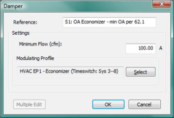
Figure 4 - 21 : Mixing damper set dialog.
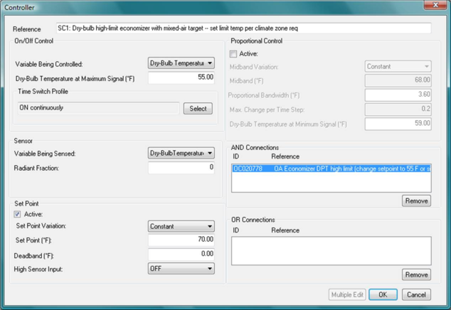
Figure 4 - 22 : Example controller dialog as set up for modulating the damper to a target mixed-air dry-bulb temperature for a typical outside air economizer. Note that this particular controller also has an AND reference to a dependent controller with sensor that provides an outdoor air dew-point temperature high limit. In this example, the controller will modulate the damper, mixing outside air and return air to get as close as it can to achieving a target mixed-air temperature of 55 ° F. Whenever the sensed outdoor temperature exceeds either of the high limit values—70 ° F DBT and 55 ° F DPT in this example, the controlled damper set will shut down to its minimum flow setting for the left branch (outdoor air).
In the case of outside-air economizer damper applications, the flow into the left-hand branch is subject to the minimum value specified by the Minimum flow parameter, with three exceptions:
-
The flow from the left branch will be less than the set minimum when the total demand for outflow (mixed-air) is less than the minimum outside air value. In this case, the flow into the left-hand branch is simply equal to the outflow at any given time step.
-
The flow on the left-hand inlet branch will be increased above the minimum, such as in the case of airside economizer “free cooling,” CO
2-based demand-controlled ventilation (DCV), as determined by a controller pointed to the downstream (mixed-air) node of the damper set. The controlled variable for economizer operation is normally a target mixed-air temperature, for DCV it is usually a percentage flow. See the DCV examples illustrated below for systems that combine OA economizer and DCV operation.
-
An RA Damper component connected to the vertical (bottom) inlet branch on the Mixing Damper will override the set minimum outside air when the total demand for supply air at the mixed-air node exceeds the total of available return air plus the minimum OA. This is intended mainly for use in building, such as laboratories, for which there are multiple means of exhaust/extract from spaces served by the system. While it would be possible to create a detailed schedule for the minimum OA makeup air requirement, this is not necessary at the system OA damper, so long as the air balance is always provided for at the zone level.
The Mixing Damper is used to determine the fraction of downstream flow demand that is drawn from the left inlet branch vs. the bottom inlet branch. The mixing damper component can be used only where total flow at the mixed-air (outlet) is determined downstream of the damper set, and not where flow is otherwise determined on either upstream branch. In other words, while flow paths, sources, and conditions can be determined upstream of a mixing damper, and mixing dampers can be used in series, the actual airflow volume at the downstream node of a mixing damper must be determined on a downstream branch. Configurations for which flow is otherwise determined on either inlet branch upstream of the mixing damper will pass a network check, but will not run at simulation time. Therefore, this component will, in most cases, be used only at or near the system inlet.
When the controller’s profile is on, the damper set component modulates the flow into its left-hand branch (normally the fresh air inlet) either to a percentage of the flow leaving the device or to get as close as it can to a target mixed-air temperature. The leaving flow rate will have been determined by flow demands downstream.
The time switch profile within the controller that is controlling the damper modulation is interpreted as an on/off switch, ON when the profile value is greater than 50% and OFF otherwise. This is in contrast to the behavior of a time switch profile used either to schedule or to modulate the minimum flow on the left branch or when a volume flow controller.
Percentage flow control can be applied only to mixing damper sets and divergent “T” junctions (which can thus act as flow-splitting dampers), and must be applied at the control node immediately downstream of the mixing damper set.
Reference
Enter a description of the component. The reference is limited to 100 characters. It is for your use when selecting, organizing, and referencing any component or controllers within other component and controller dialogs and in the component browser tree. These references can be valuable in organizing and navigating the system and when the system model is later re-used on another project or passed on to another modeler. Reference names should thus be informative with respect to differentiating similar equipment, components, and controllers.
Damper Minimum Flow
This parameter sets a minimum value for the flow into the left-hand branch of the damper set. Independent of whether the on/off control within the associated controller used to modulate the damper position above the minimum flow is on or off, the flow into the left-hand branch will be subject to a minimum which is the lesser of this minimum value and the flow rate demanded at the damper outlet by downstream controllers.
|
Warning Limits (l/s)
|
0.0 to 25000.0
|
|
Error Limits (l/s)
|
0.0 to 900000.0
|
Modulating Profile
The modulating profile in the mixing damper set can serve at least two functions:
· A schedule can be used to enforce the minimum outside air (flow from the left branch) during only occupied hours of building operation, thus allowing the outside air damper to close completely during unoccupied hours. This is a typical means of avoiding unnecessary heating of outside air when system fans switch on the middle of the night or weekends to maintain a setback temperature.
· A modulating profile can be used to vary the minimum flow rate based upon either a schedule or a formula profile referencing a value such as outdoor dry-bulb temperature.
Demand-controlled ventilation based upon zone-level CO2 is provided not by modulating profile, but by attaching a proportional controller to the damper set with a CO2 sensor on the downstream node of the occupied zone(s)/room(s) as illustrated below. Note the branch of the damper set to which the controller is pointed.
Mixing Damper Application: CO2-based Demand-Controlled Ventilation (DCV) example
For CO2-based demand-controlled ventilation, the controlled variable for outside air (OA) can be either flow rate (cfm or l/s) into the left branch of the damper set or the fraction from the left branch as a percentage of the total mixed-air flow rate. However, the latter is much more flexible and useful, as it allows independent zone-level controllers with CO2 sensors to “vote” on the system-level outside-air damper position, without having to know at any given time step what the actual flow rate at that damper is.
If there are multiple zones “voting” on the fraction of outside air as a function of individual CO2 levels (via multiplexed controllers responding to sensed room CO2 levels), the controlled variable will normally be percentage flow. For 100% outside air systems, as in the second example below, zone-level flow rates can be controlled to maintain desired CO2 levels. No OA damper is required.
If outside airflow above the minimum required for ventilation and/or makeup air is controlled to a target mixed-air temperature, as is most typical means of outside air economizer control, a duplicate damper will need to be included for raising the fraction of outside air when demanded by zone CO2 levels. This is because all controllers pointing to a given node must use the same controlled variable in order to facilitate voting.
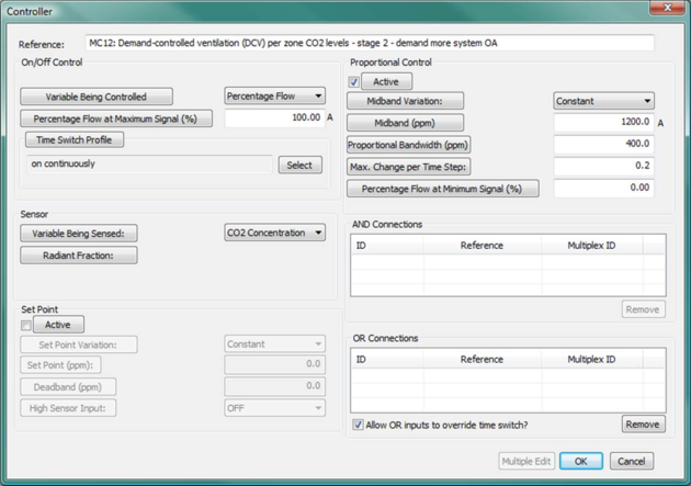
In the application illustrated below, each zone votes for additional OA at the system level as the zone CO2 exceeds a set threshold (see the highlighted controller and associated controller dialog). A second damper component, in additional to the normal OA economizer, just below and to the left of the OA economizer damper. This represents a second copy of the same actual damper, but with a different controlled variable. While the OA economizer is controlled to modulate the fraction of outside air to meet a desired mixed-air target temperature, with an outside temperature high-limit, at or above which it will shut down to the set minimum OA flow, the added DCV damper can add more OA based on zone demand. The zone-level DCV controllers “vote” on the amount of additional OA needed at any give time. The highest vote from zone-level DCV controllers modulates the system DCV damper from 0 to 100% as zone CO2 concentration rises from 1,000 to 1,400 ppm. In other words, when it is desirable to bring in more OA to maintain the set mixed-air temperature, the first damper will prevail. When it is desirable for maintenance of appropriate zone CO2 levels to introduce more OA than otherwise provided by the thermally driven OA economizer, the added damper will prevail. Neither can ever bring in more OA than is demanded by the system. Both will have equal priority in determining how much OA is brought in at any given time.
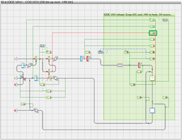
Figure 4 - 23 : Illustrative HVAC network configuration with added outside-air damper and controller for CO2-based demand-controlled ventilation in a mixing (recirculating) system.
Figure 4 - 24 : Illustrative controller dialog for CO2-based demand-controlled ventilation in a mixing (recirculating) system. This controls the percentage flow in the added copy of the outside-air damper, thus overriding the outside-air flow rate otherwise determined by thermal considerations for the normal economizer damper operation, as needed to maintain set zone CO2 levels.
A second example (below) illustrates an appropriate configuration for control of the zone-level outside air ventilation rate with a 100% outside air system. This is typical for ventilation systems used with fan-coil units, active chilled beams, and similar terminal equipment. In this case, some zones can use constant-volume ventilation and others can have ventilation rate varied according to CO2 concentration in the zone.
Figure 4 - 25 : The system network example above illustrates a configuration for CO2-based demand-controlled ventilation in a 100% outside air system (i.e., with no recirculation). This example is a fan-coil system, but could easily be modified to model active chilled beams (induction units), passive chilled beams, or chilled ceiling panels. For all zones with DCV, the highlighted controller must use room CO2 as the sensed variable for control of the primary zone airflow rate. Other zones can simply use a fixed flow rate (e.g., identical values for the flow rate at min and max sensor signals).
Note that the damper set at the system inlet is a face & bypass damper for the energy recovery device, and has no influence on the fraction of outside air. A separate controller in this example determines the fraction of air that air passes through or around the heat/enthalpy recovery device based upon zone temperatures, and thus whether additional fan energy is consumed as a result of added static pressure when recovering thermal energy.
Return Air Damper Set

Toolbar button for placement of the RA Damper component

RA Damper component on the network
The Return Air (RA) Damper Set component incrementally increases the minimum flow of outside air (makeup air) entering the system via the economizer damper when required. In other words, it can, as needed, override the minimum OA setting in the intake air mixing damper component.
The RA Damper Set is intended for use only with the Mixing Damper Set, and this is assumed to be when the latter is functioning as an outside air (OA) economizer—i.e., when it is mixing OA and RA flows. The RA Damper has no user inputs and performs its function only when paired with the Mixing Damper Set. In order for the two to be linked, the RA Damper must be present on the vertical branch entering the OA economizer damper. There can be no junctions between them. If it is not paired with the Mixing Damper in this configuration, and thus linked the OA damper, it will revert to functioning as a simple “T” junction.
The capability of the RA damper link to automatically “override” the minimum OA setting within the OA damper is useful in the case of any system for which the sum total of RA plus minimum OA available to the system may occasionally be less than the collective demand for primary supply airflow to the conditioned zones. This may occur, for example, when there are separately exhausted zones (lavatories, copy rooms, janitor’s closet, locker rooms, etc.) or variable-volume vent/fume hoods (e.g., in laboratories, hospitals, industrial environments, etc.) removing air from the system according to schedules or sensed variables that are independent of the primary airflow controls to the conditioned zones that feed them.
Another way to think of this is that the RA Damper can override the minimum OA setting when the total demand for supply air at the mixed-air node exceeds the total of available return air plus the minimum OA. This is intended mainly for use in buildings, such as laboratories, for which there are multiple means of exhaust/extract from spaces served by the system. While it would be possible to create a detailed schedule for the minimum OA makeup air requirement, this is not necessary at the system OA damper, so long as the air balance is always provided for at the zone level.
The RA damper does not, however, obviate the need to otherwise specify airflow rates so that other braches on the system, such as transfer air paths, are not starved of airflow when the minimum flow from upstream branches, or the schedule thereof, constrains what is available downstream.