Ductwork Thermal Properties
When supply ducts pass through notably warm spaces, such as return-air plenums, or when supply and/or return ducts are located outside of the building envelope it is often desirable to model the heat gain to or heat loss from ductwork. Heat lost from hot ducts is gained by the room air through which the duct runs pass (where additional heat may or may not be needed). Similarly, heat gained by cold supply ducts passing through a hot return plenum will raise the supply air temperature and provide unintended cooling to the return air, some or all of which is typically exhausted from the building.
The Duct Thermal Properties dialog also includes duct leakage settings. VistaPro and Loads Reports provide results for leakage and thermal gains & losses, both with respect to the air flowing in the ducts and the recipient spaces.


Toolbar buttons for ductwork thermal properties (horizontal and vertical components).


Ductwork thermal properties component.
Reference
Enter a description of the component. The reference is limited to 100 characters. It is for your use when selecting, organizing, and referencing any component or controllers within other component and controller dialogs and in the component browser tree. These references can be valuable in organizing and navigating the system and when the system model is later re-used on another project or passed on to another modeler. Reference names should thus be informative with respect to differentiating similar equipment, components, and controllers.
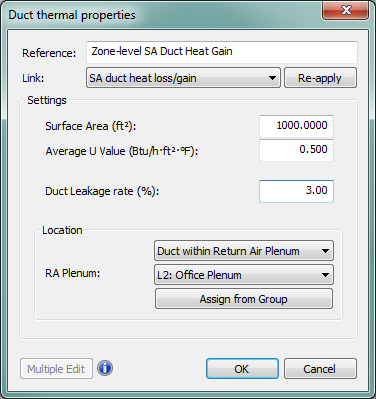
Figure 4 - 28 : Ductwork thermal properties dialog shown with ductwork leaking into a return air plenum
Surface Area of Duct
Enter the approximate surface area of the duct(s).
|
Warning Limits (m²)
|
5.0 to 100.0
|
|
Error Limits (m²)
|
0.1 to 10000.0
|
Average U-value of Duct
Enter the average U-value of the duct. The duct U-value is used together with the duct surface area to calculate the heat transfer between the duct and the adjacent room (or outside).
|
Warning Limits (W/m²K)
|
0.1 to 10.0
|
|
Error Limits (W/m²K)
|
0.01 to 99.0
|
Duct Leakage Rate
Enter the average rate of duct leakage. The duct leakage rate is used together with the supply airflow during simulation to determine the amount of air leaking from the ductwork. If the duct leaks into a plenum, zone, or room in the model, the leaked air contributes to the performance of those spaces.
Duct leakage rate also contributes to the total system supply air flow. In a typical variable air volume system, the supply air provided by an air handling unit at any given timestep will be the airflow required at the zone or space level plus the duct leakage rate.
Location
Set the location of the ductwork to be “external to building” (outside the conditioned envelope), “within Return Air Plenum”, “within Supply Air Plenum”, “within Zone”, or “within Room”. If the duct is located external to the building, no further action is required. If the duct is located within the building, the space or zone containing the duct must be selected. Available choices for the space or zone containing the duct are filtered by the selection of duct location (i.e., only return air plenums are available for selection if “Duct within Return Air Plenum” is chosen).
Room Containing Duct
Select an indoor location of the ductwork (an actual space in the model), if the location is not set to external. The flow of heat and air between the duct and space is modeled for both the air system and the space.
An option is provided to Assign from Group, allowing for Space Grouping schemes to be used to assign several layers of a multiplex in one step.