Toolbar button for placement of a heating coil

Heating coil component
Background
ApacheHVAC provides two levels of heating coil models for use in HVAC systems. A Simple heating coil model uses a simplified approach to determining coil heat transfer characteristics and assumes constant waterside temperature change through the coil. An Advanced model more explicitly models both airside and waterside heat transfer providing a more detailed and accurate calculation of coil heat transfer and corresponding airside/waterside properties. The Advanced model provides the necessary modeling detail to support explicit waterside modeling contained in Hot Water Loop configurations. The Advanced model also provides more detailed coil specification methods so that coils may be better sized or selected from manufacturer data for specific HVAC system configurations. This facilitates more accurate determination coil design and off-design performance.
Both Simple and Advanced heating coil models are accessed through the toolbar heating coil button and heating coil component dialog. An HVAC system configuration can contain both Simple and Advanced models; however, individual multiplex layer instances of a coil occupying a particular location must all be of the same coil model type (i.e., all Simple OR all Advanced models).
Simple models can be served by a Hot Water Loop, Generic Heat Source, Water-to-Air Heat Pump, or Air-to-Air Heat Pump. Advanced heating coil models can be served only by a Hot Water Loop.
Simple Model
The Simple model requires only two input values to set the coil performance: Heating capacity and Over-sizing factor. The Simple model is recommended early in the design process when detailed coil data or performance is not required. It does not, however, account for changes in HWL supply temperature.
Advanced Model
The Advanced model is more detailed and accurate characterization of the heat transfer process of a heating coil. The Advanced model uses more detailed coil design parameter specification and enhanced heat transfer modeling capability. One of the features of the Advanced model is the ability to design (i.e., “size”) the heating coil for the specific HVAC system application. In this context, “size” refers to determining the coil heat transfer characteristics at a design point. With these design point characteristics, the heating coil can then be more accurately modeled at both design and off-design operating conditions. The Advanced heating coil is automatically sized by the system Autosize process, but sizing parameters can also be modified manually to provide user flexibility.
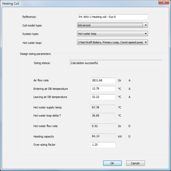
The Advanced model dialog facilitates the design sizing process by immediately “sizing” the heating coil for the current state of design sizing inputs. Typical default coil design values are provided to aid in the initial sizing process. Editing a design parameter will automatically and instantly re-size the coil, and the new sizing parameters, Hot water design flow and Heating capacity, immediately displayed. A Sizing status message box indicates the state of the sizing process including error conditions resulting from out-of-range or inconsistent input parameters.
Autosizing Process
The Autosizing process is designed to give the ease of specifying a single heating coil design parameter coupled with the System Sizing feature to complete the required design inputs for the Advanced coil. In Autosizing mode, the user sets the coil Over-sizing factor, then invokes the System Sizing process to populate the remainder of the airside parameters. These parameters, combined with the input Over-sizng factor, complete the design point specification for the heating coil. In addition, prior to or after System Sizing data has been obtained, the user may also change any of the autosized parameters (or Over-sizing factor) at any point to set a new coil design point.
Manual Sizing Process
In contrast to Autosizing, Manual sizing process allows the user to input all the necessary airside and waterside conditions that set the cooling coil design point. Manual mode has two basic approaches. One is to allow input of a manufacturer specified (i.e., catalogue) cooling coil. In this case, the heating coil used in the HVAC system model will correspond to an actual physical coil. The second approach is to allow the user to “design” their own cooling coil in order to understand the impact of the design parameters on the overall system. With the interactive functionality of the Advanced model dialog, this information is given immediately to the user.
Heating Coil Dialogs
There are two cooling coil dialogs, each specific to the type of coil model desired. The Simple coil model is the default when selecting a heating coil from the toolbar. The Simple coil model dialogs are shown below corresponding to the types of systems that serve the coil.
Figure 4 - 5 : Simple heating coil dialog with coil served by hot water loop
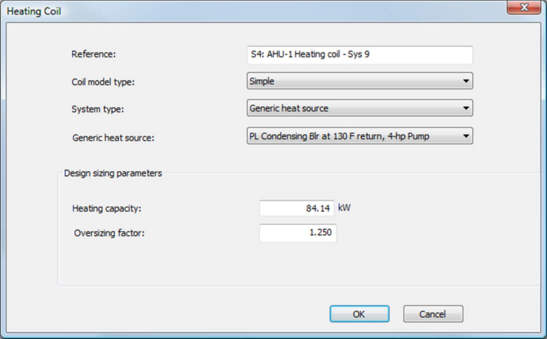
Figure 4 - 6 : Simple heating coil dialog with coil served by a generic heat source
The user may select the Advanced coil model from the Simple model dialog. Once selected, the Advanced model dialog will open automatically upon selecting the particular coil. The Advanced model dialog is shown below.
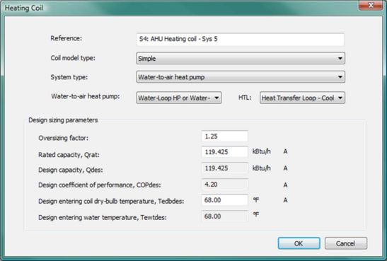
Figure 4 - 7 : Simple heating coil dialog with coil served by a Water-to-air heat pump
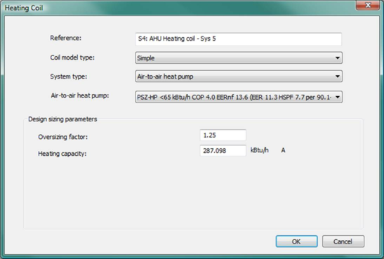
Figure 4 - 8 : Simple heating coil dialog with coil served by an Air-to-air heat pump
Figure 4 - 9 : Advanced heating coil dialog
The upper portion of both the Simple and Advanced model dialogs contain information for specifying the reference name, coil model type, and system type serving the coil. The lower section of the dialog contains the Design sizing parameters appropriate for each model type. Detailed descriptions of these parameters are provided below.
Reference
Enter a description of the component.
Coil Model type
Coil model type may be either Simple or Advanced.
System type
Select a system type serving the coil, “Generic heat source” or “Hot water loop.” Note that Advanced heating coils may only be served by Hot water loops.
System name
Select a defined system of the “System type” specified.
Design Sizing Parameters for Simple Coil Model
The following design parameters are common to a simple heating coil served by systems other than the water-to-air heat pump (generic heat source, hot water loop, or air-to-air heat pump). For a simple heating coil served by a water-to-air heat pump, there are some special parameters required by the water-to-air heat pump system type. Please see section 2.9.10 for details of these special parameters for a water-to-air heat pump served heating coil.
Heating capacity
|
Default Values
|
84.14 kW
|
287.10 kBtu/h
|
|
Typical Range
|
0.50 to 250.00 kW
|
1.71 to 853.04 kBtu/h
|
|
Error Limits
|
0.05 to 1000000.00 kW
|
0.17 to 3412141.29 kBtu/h
|
Enter the maximum Heating capacity of the heating coil. The simulation will limit the output from the coil to this capacity as an absolute maximum under all operating conditions. Furthermore, because the simple model does not account for water temperature or flow rate in the case of a hot water loop, it will place heat load on the loop up to its maximum capacity without regard for loop-related limitations.
Over-sizing factor (all system types)
Specify the factor by which the heating coil capacity is increased relative to the peak calculated value during autosizing. This does not influence the manually entered capacity unless it is subsequently overwritten by the autosized value.
|
Default Values
|
1.25
|
|
Typical Range
|
1.00 to 1.50
|
|
Error Limits
|
0.00 to 5.00
|
Design Sizing Parameters for Advanced Coil Model
Sizing status
The Sizing status message box provides information on the state of the coil sizing process. This includes error messages for out-of-range or inconsistent design parameters. A summary of the Sizing status messages is provided below.
|
Heating Coil – Advanced Model
Sizing Status Summary
|
|
Status
|
Comment
|
|
Ready for Sizing
|
Required input values have been entered.
|
|
Calculation successful
|
Coil has been sized using displayed parameters.
|
|
Entering air DBT must be less than or equal to leaving DBT
|
|
|
Entering air dry bulb temperature must be less than the leaving HWL temperature.
|
|
|
Leaving air dry bulb temperature must be less than the entering HWL temperature
|
|
Air flow rate
Air flow rate is the volumetric air flow entering the coil. In the Autozing process, peak air flow rate is determined by the System Sizing process. When an autosized air flow rate is displayed, the value and Autosize indicator will be indicated in green However, air flow rate still be edited from the autosized values (the value will return to black with corresponding “A”). Note that this air flow rate is only used in for determining the coil heat transfer parameters and not used by any flow controllers associated with the HVAC system on which the coil resides.
|
Default Values
|
2831.68 l/s
|
6000.00 CFM
|
|
Typical Range
|
94.39 to 14158.42 l/s
|
200 to 30000 CFM
|
|
Error Limits
|
0.00 to 471950.00 l/s
|
0.00 to 1,000,000.00 CFM
|
Entering air dry (DB)
Entering air dry (DB) is the air stream condition entering the coil. These temperatures must be specified in both the Autosizing/Manual process. In Autozing, peak design value for this temperature can be determined by the System Sizing process. When an autosized temperature is displayed, the value and Autosize indicators will be shown in green. However, the temperature can still be edited from the autosized value (the value will return to black with corresponding “A”).
|
Default Values
|
12.78 ° C
|
55.00 ° F
|
|
Typical Range
|
-17.78 to 50.00 ° C
|
0.00 to 80.00 ° F
|
|
Error Limits
|
-100.00 to 100.00 ° C
|
-148.00 to 212.00 ° F
|
Leaving air dry (DB)
Leaving air dry (DB) is the condition of the air steam exiting the coil. Leaving air DB temperature must be specified in both Autosizing/Manual processes. In Autosizing, required leaving air DB temperature to meet the system load can be determined by the System Sizing process. When the Autosized temperature is displayed, the value and Autosize indicators will be shown in green. However, the temperature can still be edited from the autosized value (the value will return to black with corresponding “A”).
|
Default Values
|
32.22 ° C
|
90.00 ° F
|
|
Typical Range
|
26.67 to 37.78 ° C
|
80.00 to 100.00 ° F
|
|
Error Limits
|
-100.00 to 100.00 ° C
|
-148.00 to 212.00 ° F
|
Hot water loop supply temperature and Hot water loop delta temperature
Hot water loop supply temperature is the design hot water temperature entering the coil. Hot water loop delta temperature is the design hot water temperature drop through the coil. Both values are linked to the corresponding Hot water loop parameters (see HWL Sec.
2.4 ) serving the coil and non-editable in the Advanced heating coil dialog. These parameters may be edited in the corresponding HWL dialog and the edited values automatically updated in the Advanced heating coil dialog.
Hot water loop flow rate
Hot water loop flow rate is the design hot water flow rate serving the coil. This value is calculated from the other coil design sizing parameters. Note that this value is adjusted by the Over-sizing factor specified. In the simulation, the necessary hot water flow rate is determined by the coil model to meet the relevant control requirements. However, the simulation will limit the hot water flow rate to the coil at this value even if the associated control requirements are greater.
Heating capacity
Heating capacity is the design heat transfer capacity of the coil. This value is calculated from the other coil design sizing parameters. Note that this value is adjusted by the Over-sizing factor specified.
Oversizing factor
The factor by which the coil design values for hot water flow rate and heating capacity are increased relative to the autosized values. Airside parameters (flow rate, entering air DB temperature, and leaving air DB temperature) are NOT adjusted by the over-sizing factor.
The coil design heat transfer with the over-sizing factor is:
|
Default Values
|
1.25
|
|
Typical Range
|
1.00 to 1.50
|
|
Error Limits
|
0.00 to 5.00
|
Advanced Model Design Parameters Summary
The Advanced model design parameters are summarized below.
|
Heating Coil – Advanced Model
Design Parameters Summary
|
|
Coil Design Parameter
|
Status
|
Comment
|
|
Air flow rate
|
Autosized Value
Editable
|
Editable before/after System Sizing
Dialogue will check for errors and consistency
|
|
Entering air DB temperature
|
|
Leaving air DB temperature
|
|
Hot water supply temperature
|
From HWL
Non Editable
|
|
|
Hot water loop delta T
|
|
Hot water flow rate
|
Derived Value
Non Editable
|
|
|
Heating capacity
|
|
Over-sizing factor
|
User Input
Editable
|
|