The fan component is used to determine the required fan power at a given flow rate, and thus energy consumption of the fan, and to account for the temperature rise in the air stream.

 Toolbar buttons for placement of left- and right-intake fans
 Left- and right-intake fan components
The fan component does not actively influence the flow rate; the values entered here do not determine airflow through the system. Rather, these values are used solely to calculate the consequential energy consumption and effect on air temperature at a given flow rate. Fan power, and thus energy consumption and heat addition, are calculated as a function of fan and motor efficiencies and the resistance to airflow that must be overcome to provide the desired flow rate.
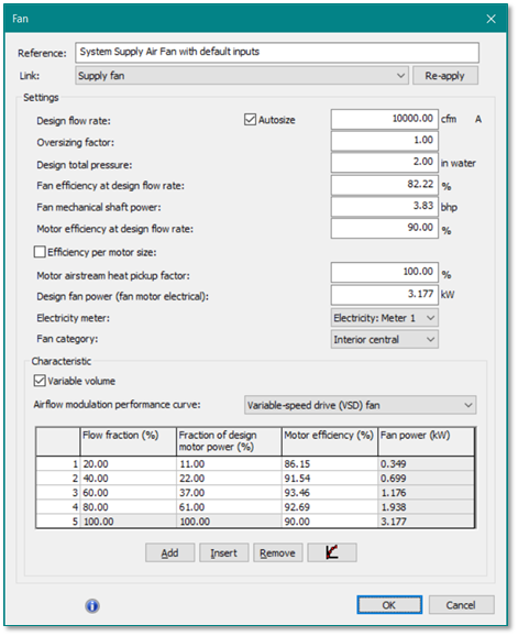
Figure 4-1: Fan dialog with default inputs.
The combination of flow, pressure, and efficiency is used during the simulation to calculate the electrical power consumption and fan heat input to the air stream as follows:
The increase in total internal energy of the air, , after leaving the fan is given by:
The resulting temperature increase,  is then given by:
The fan motor power consumption is given by  , which is determined by the definition of
  :
:
|
Where
|
|
|
|
= Design flow rate in kg/s, equivalent to 
|
|
|
= Design total pressure rise in Pa, equivalent to 
|
|
|
= Design fan efficiency, equivalent to 
|
|
|
= Design motor efficiency, equivalent to 
|
|
|
= Motor airstream pickup factor
|
|
r
|
= Air density
|
|
|
= Flow fraction
|
|
|
= Fraction of design power, 
|
|
|
= Motor efficiency
|
In simulation, as the number of fan data points is not infinite, for any flow fraction  , the power consumption is determined by linear interpolation of the
  to .
to .
Similarly, the temperature rise in the airstream,  , is calculated via Equation 4.1.2 by interpolating
  and
and  .
.
Pressure rise refers to the total static pressure (internal plus external) to be overcome by the fan. Efficiency inputs are provided for both the mechanical efficiency of the fan and the electrical efficiency of the motor and associated power electronics (e.g., a variable-speed drive). For variable-volume systems, the flow fraction, fan power fraction, and motor efficiency need to be defined at multiple points on a fan curve.
It is important to realize that the fan dialog inputs and curve data must account for the total pressure resulting from the system components and configuration (dampers, filters, coils, ducts, diffusers, etc.) as well as the type of airflow and fan controls. For example, a given fan on a variable-flow system would have differing performance depending on whether the airflow rate is throttled by a downstream damper or modulated by variable-speed drive on the fan motor. With variable-speed fan control, the pressure either will drop with flow or will be maintained at a constant value (e.g., per the positions of downstream VAV box dampers) as the basis for fan speed control. In either case, both fan power and heat addition will fall with airflow rate. For the damper-controlled (throttled) flow rate, on the other hand, fan speed will be roughly constant and the pressure, fan power, and heat gain will tend to rise as flow is restricted by the damper.
Fan Heat Gain: All electrical energy used by a supply air fan eventually ends up heating the air around the motor, at the fan, within the ducts, at the diffuser, and within the spaces to which the air is supplied. When the airflow dissipates within the receiving spaces, 100% of the energy put into the fan will have become heat somewhere along the way. Therefore, all fan energy input other than the fraction of motor heat (per motor efficiency) excluded from the airstream by the “Motor airstream heat pickup factor” heats the supply air. Given the practical limits of simulation, all of this heat gain is assumed to accrue at the fan component, rather than in a more distributed manner both at the fan and as associated with each source of friction along the airflow path. Regardless of where it occurs in the actual system, this heat gain is a cooling load.
Reference
Enter a component description. Reference names should be informative with respect to differentiating similar equipment, components, and controllers. The reference is limited to 100 characters. It is for your use when selecting, organizing, and referencing any component or controllers within other component and controller dialogs and in the component browser tree. These references can be valuable in organizing and navigating the system and when the system model is later re-used on another project or passed on to another modeler.
Link
The selected Link affects how the System Parameter interface for the HVAC system and certain autosizing and simulation routines interact with the Fan component. For example:
· When the fan component Link is set to ‘Supply Fan’, the Design flow rate value in the dialog is bi-directionally linked to the System supply fan design flow rate value in the System Parameters dialog, where users can choose to override the autosized flow rate value with a manual entry without losing the autosized value.
· When the fan component Link is set to ‘FCU Fan’, the System Parameters dialog sees this as a zone-level recirculation fan in a fan-coil unit, and thus linked to the settings for Terminal unit fan control. Whereas 3 of the 4 options for this parameter (constant, two-speed, and variable) influence the fan operation the via just the settings in related airflow controllers, the ‘Cycle on with TU load’ option also causes the fan component to cycle on/off with the compressor when one or more coils within the same terminal unit (on the same multiplex layer) are of the type AAHP, WAHP, or DX Cooling.
Design flow rate
The Design flow rate (cfm or l/s) can be manually entered or, more commonly, autosized. When autosized, this is the maximum flow required at the particular fan component during the system-level sizing run, multiplied by the Oversizing factor on the next line. See description of the Link parameter above regarding the coupling of this value to the System Parameters dialog when this is a system ‘Supply Fan’, and capability for overriding the autosized value with a manual fan size while preserving the autosized value for reference.
Oversizing factor
The oversizing factor is applied to the maximum flow required at the particular fan component during the system-level sizing run to determine the autosized Design flow rate, above.
Design total pressure
Enter the total fan static pressure (iwc or Pa ) at the design flow rate, including both internal pressure (resulting from filters, coils, and other air handler components) and external pressure (from ductwork, terminal units, etc.).
|
Warning Limits (Pa)
|
150.0 to 2000.0
|
|
Error Limits (Pa)
|
10.0 to 90000.0
|
Fan efficiency at design flow rate
Enter the efficiency (%) of the fan impeller at the design flow rate. This is a bi-directionally derived value with respect to Fan mechanical shaft power. If the Fan efficiency at design flow is edited, the Fan mechanical shaft power will be calculated based upon this value, and vice versa.
Fan mechanical shaft power
The Fan mechanical shaft power (bhp or Nm/s) contributes to the calculation Design fan power, and is a bi-directionally derived value with respect to Fan efficiency at design flow rate. If the Fan mechanical shaft power is edited, the Fan efficiency at design flow will be calculated based upon this value, and vice versa.
Motor efficiency at design flow rate
Enter the efficiency (%) of the fan motor at the design flow rate.
Motor efficiency at design flow rate is a bi-directionally derived value with respect to Design fan power. If the Motor efficiency at design flow rate is edited, the Design fan power will be calculated based upon this value, and vice versa.
In the case of a variable-volume fan, motor efficiency for off-design flow fractions are entered as part of the performance curve data in the table at the bottom of the dialog. Once the motor efficiency values for each flow fraction have been entered in the data table, editing the value on this line will automatically revise both the curve data value at 100% flow in the data table to match this value, and will proportionally adjust all values entered for lesser flow fractions to maintain the curve.
Efficiency per motor size
When this tickbox is checked, the motor efficiency value is set according to the motor horsepower. The values are taken from a lookup table of minimum motor efficiency requirements per motor size, as given by the California Energy Commission for Title-24 Energy Code compliance (ACM Manual Table 11).
The basis for determining the lookup table value can, per the two radio buttons, be either Fan mechanical shaft power two lines above or the selection from a list of a standard motor sizes based on “Nameplate” horsepower.
As it is based upon U.S. Standard motor sizes given in terms of horsepower, this alternative means of setting motor efficiency is available only when working in IP units.
Motor airstream heat pickup factor
This factor (%) determines the extent to which the fan-driven airflow will be heated by motor losses (the fraction of electrical input converted to heat rather than mechanical shaft power, given the motor is not perfectly efficient). Depending on whether the fan motor is located within the airstream or not, there will be greater or lesser heat pickup associated with the fan motor in particular.
For fans for which motor is located within the airstream, a figure of 100% should be used. For fans where the motor is located outside of the airstream, this will be less than 100%. As there will always be some motor heat dissipated through the motor shaft into the fan itself, a Motor airstream heat pickup factor of 0% would be unrealistic. This is the reason for the warning at 10% given below.
|
Warning Limits (%)
|
10.0 to 100.0
|
|
Error Limits (%)
|
0.0 to 100.0
|
Placing the fan motor outside the HVAC airstream in an actual building may reduce direct airstream heat pick-up at the fan motor location; however, this would reduce the overall Fan Heat Gain (e.g., by 10% in the case of a 90% efficient motor) only when the fan motor is also located in a non-conditioned space, such as within an isolated section of an AHU enclosure sitting either on the roof or otherwise outside the building. When the actual motor is still within a space that is cooled by the system, any heat not directly introduced to the airstream is still contributing to space cooling loads that the system must address.
Fan Heat Gain: As explained under the more general discussion of Fan Heat Gain (above), all fan energy input other than the fraction of motor heat excluded from the airstream by the “Motor airstream heat pickup factor” heats the supply air. Ultimately, during system cooling operation, all of this heat ends up in the spaces to which the air is supplied, and thus presents a cooling load (or a contribution to reheat where applicable). Given the practical limits of simulation, all of this heat gain is assumed to accrue at the fan component, rather than in a more distributed manner both at the fan and as associated with each source of friction along the airflow path.
Regardless of where it occurs in the actual system, this heat gain must be addressed. It may contribute to reheat, including the offset sub-cooling below the target system supply temperature for dehumidification, provide a minor source of heat in heating mode, and/or contribute to the cooling load.
As cooling load, regardless of the blow-through vs. draw-through configuration of the system fan and cooling coil, the same total load must be addressed: If blow-through, the fan heat gain will be added to the entering air at the coil, and thus must be directly dealt with by the coil; if draw-through, the coil leaving air temperature (LAT) needs to be reduced to compensate for downstream fan heat gain in order to provide the desired system supply air temperature.
If assuming that some of the heat gain in the actual building may occur further downstream—e.g., as the air encounters friction in ducts, VAV dampers, reheat coils, diffusers, and finally bumping into the air already in the receiving spaces—the alternative would be to provide at least some of the compensation via increased airflow volumes. In any case, however, the resulting load at the cooling coil will be the same.
Temperature rise from fan heat gain is typically on the order of 0.5–2 F (0.28–1.11 K). For example, if the total pressure the fan must overcome at the design condition is 2 inches water column (iwc), with fan efficiency of 74% and motor efficiency of 90%, and the motor fully within the airstream, the temperature rise for typical system airflow rates will be approximately 1 F. If the pressure is higher or the fan less efficient, the temperature rise will be greater.
Design fan power (fan motor electrical input)
Design fan power is calculated based upon the values above for Design flow rate, Design total pressure, Fan efficiency and thus mechanical shaft power at design flow rate, and Motor efficiency at design flow rate.
Design fan power is a bi-directionally derived value with respect to Motor efficiency at design flow rate. If the Design fan power is edited, the Motor efficiency at design flow rate will be calculated based upon this value, and vice versa.
Electricity meter
Select the desired electrical meter (default Meter 1 or user defined) for reporting fan energy consumption. This will be in conjunction with other energy end uses assigned to the same meter.
Fan category
The Fan category is used to determine the fan application, as a subset of all HVAC system fans, within which the energy for a particular fan will be reported. This is essential for certain code compliance and rating system reports, such as is provided for LEED EA credit 1 documentation.
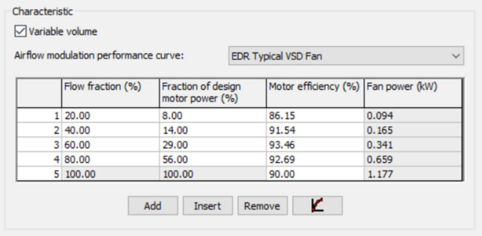
Characteristic – Variable vs. Constant Volume
For constant-volume fan systems, the inputs above are all that’s needed. The Variable volume checkbox enables the additional user interface for selecting, editing, and viewing fan performance curve data.
Airflow modulation performance curve
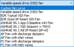
Users can select from any of the listed pre-defined fan performance curves, or enter custom curve date into a blank table. All data for pre-defined curves is editable once loaded. Editing a pre-defined curve changes the curve selection to ‘Custom fan curve’.
Fan curve data inputs
· Flow fraction (%) defines each data point in terms of a fraction of fan design airflow.*
· Fraction of design motor power (%) is the fraction motor power at the Flow fraction data point.
· Motor efficiency (%) is the efficiency of the motor at the Flow fraction data point.
· Fan power (kW) is calculated for each flow fraction using all of the same parameters as noted above for the Design fan power.
*Note: For the newer fan curves with 11 data points (VE2021 and onward), the data point at 0.01% flow simply provides a non-zero flow fraction to support the derivation of a fan power value at that is effectively zero flow, whilst avoiding a divide-by-zero error. This allows for interpolation of fan power values between zero flow and the smallest flow fraction data point in the data table. In most systems, however, the airflow will be constrained to a minimum operating fraction that is greater than or equal to the minimum flow fraction set in the fan curve data.
For supply fans, minimum flow is set within the System Parameters dialog (the default is 10%). In this and all other cases, the minimum flow is actually determined by the airflow controllers on the system air network. The fan component simply determines the fan power required for the flow rate collectively given by all downstream airflow controllers; the fan component model does not determine the flow, and thus has no way to constrain it. Rather, a dependent airflow controller (located just outside the zone multiplex) with ‘Zone airflow detection’ link and logical OR connections to the airflow controllers for all zones enforces the minimum system fan flow rate whenever any one or more zones on the system requests airflow (e.g., for ‘cycle on as needed’ fan operation during unoccupied hours).
Fan curve data table edit controls
· Add button appends an additional flow fraction row at the bottom of the table, immediately above the row for 100% design flow.
· Insert button inserts a new flow row immediately above the currently selected (highlighted) row.
· Remove button deletes the currently selected (highlighted) row.
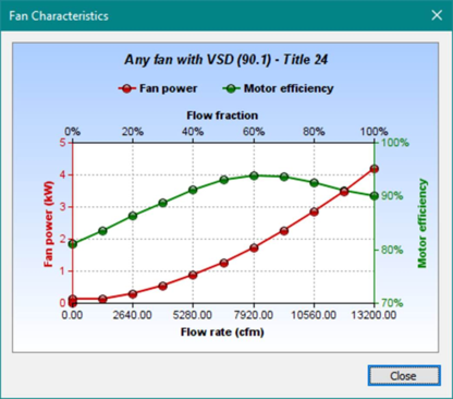
Fan Characteristic – fan curve data plot
Click the button with curve plot icon to view an XY plot of the current data in the fan curve data table.