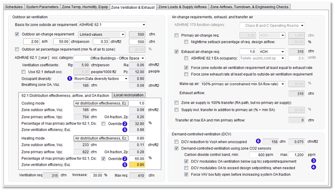
Zone Ventilation & Exhaust tab
Outdoor air ventilation
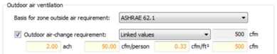
Basis for zone outside air requirement
Options: ASHRAE 62.1, OA requirement, ASHRAE 170, Maximum, or Sum
The default ‘Basis for zone outside air requirement’ can be set in ApacheHVAC Preferences > Integrated System Management > Default Parameters.
· If ‘Basis for zone outside air requirement’ is set to ASHRAE 62.1, the ASHRAE 62.1 Appendix A zone-level ventilation parameters described below are enabled, as well as the optional ‘Outdoor air-change requirement’ parameter.
· If ‘Basis for zone outside air requirement’ is ‘ASHRAE 170’, ‘Maximum’, or ‘Sum’, the A170 category selector and functionality are enabled.
· If ‘Basis for zone outside air requirement’ is “Maximum”, all parameters on the dialog are enabled, and the zone will use the greatest ventilation rate of those determined by all options and methods the user has engaged.
· If ‘Basis for zone outside air requirement’ is set to “Sum”, all parameters on the dialog are enabled, and the zone will use the sum of all ventilation rates specified/determined by all options and methods the user has engaged.
Outdoor air-change requirement
Options: Linked values (default), Maximum, or Sum
Drop-down selection of Linked values, Maximum, or Sum determines how the volume flow rate value at the end of the first line will be derived from the editable values on the second line. Linked = same behavior as in Space Data. The resulting derived l/s value overrides other ventilation calcs, if greater, and feeds into the calculation of either Maximum or Sum when these options are selected for ‘Basis for zone outside air requirement’.
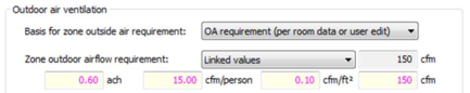
Zone outdoor airflow requirement
If ‘Basis for zone outside air requirement’ is set to anything other than ASHRAE 62.1, the two lines in ‘Outdoor air-change requirement’ above are modified as follows:
a) Label revised from ‘Outdoor air-change requirement’ to ‘Zone outdoor airflow requirement’;
b) Checkbox is remove and the parameter is enabled;
c) Initial value is from Space Data ‘System outside air supply’; magenta color text is used to indicate values from Space Data vs. user edited.
The resulting labeling and default condition are shown below:
Options: Linked values (default), Maximum, or Sum
Drop-down selection of Linked values, Maximum, or Sum determines how the volume flow rate value at the end of the first line will be derived from the editable values on the second line. Linked = same behavior as in Space Data. Revise input fields and labeling per SI/IP units mode (units for each field are otherwise fixed). The resulting derived l/s value overrides other ventilation calcs, if greater, and feeds into the calculation of either Maximum or Sum when these options are selected for ‘Basis for zone outside air requirement’.
Outdoor air percentage requirement (min % of air to zone)
This sets the OA flow rate as a percentage of the Maximum primary airflow to the zone; Any ventilation percentage entered here overrides other ventilation calculations if the derived flow rate is greater.
-
Engaging “Outdoor air percentage requirement (min % of air to zone)” will cause all three “Force … max airflow at least equal to ventilation rate” parameters on the last two tabs of this dialog to be automatically disengaged, as these are mutually exclusive features.
-
Engaging any one of the three “Force … max airflow at least equal to ventilation rate” parameters will automatically disengage “Outdoor air percentage requirement (min % of air to zone)” on the Zone Ventilation & Exhaust tab of this dialog, as these are mutually exclusive features.
ASHRAE 62.1 Appendix A zone-level ventilation parameters
If ‘Basis for zone outside air requirement” is set to ‘ASHRAE 62.1’ (or ‘Maximum’), the following set of ASHRAE 62.1 parameter is enabled.
ASHRAE 62.1 occupancy category
ASHRAE 62.1-[ YEAR ▼ ] occupancy category [ ] {ASHRAE 62.1 Table 6-1 to set Rp and Ra}
Ventilation coefficients
Rp [ ] l/(s.pers) Ra [ ] l/(s.m2) {uneditable; derived from 62.1 occupancy category; use IP units where appropriate; moved up from below, as these are set by category}
Use 62.1 default occupancy
[ ] people/100m2 Pz: [ ] people {Value for Pz is derived from 62.1 default for people/1,000 ft2 when box is checked to use that default; when the 62.1 default is not used, Pz becomes editable, and defaults to the value from Space Data (magenta value), which can be overridden by a user edit to the value for Pz.}
Occupant diversity
Options: Space Data diversity factors (default), Specify independently, A62.1 Time Averaging
[ ] {value; if ‘Space Data...’ derived & uneditable, used only in calculating Ps; if ‘Specify ind...’ editable, default=1.00; range=(0.01, 1), used only in calculating Ps; if ‘A62.1 Time Averaging’ editable and used both in calculating Ps and in conjunction with Pz in the calculation of Vbz (OA required at Breathing zone).}
Occupant diversity values specifically entered either in Space Data or zone Thermal Templates for building simulation are ignored in calculating zone ventilation requirements, but determine the number of occupants in each zone when summing these to derive the total System Population (Ps). “Specify independently” allows the user to enter a zone diversity factor to refine this input to the total System Population (Ps).
Selecting “A62.1 Time Averaging” provides an editable Occupant diversity factor—the time-weighted average population fraction allowed by 62.1-2010—by which the A62.1 Zone design occupancy (Pz) will be multiplied as input to the calculation of Breathing zone OA (Vbz).
Breathing zone OA ( Vbz )
[ ] l/s [ ] l/s.m2 {derived per A62.1 calculation requirements; uneditable. Vbz is the last zone-level 62.1 parameter calculated independent of cooling vs. heating mode. The remaining zone-level 62.1 parameters—through Evz—are calculated separately (in parallel) for cooling vs. heating modes.}
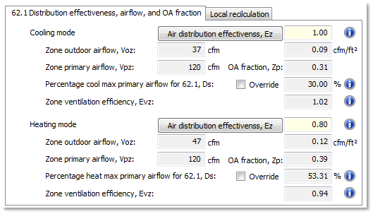
ASHRAE 62.1 Distribution effectiveness, airflow, and OA fraction (sub-tab)
ASHRAE 62.1 App. A zone-level parameters for Cooling mode
Air distribution effectiveness (Ez)
[ ] {default=1.0 for templates; range=(0.1, 2.0)} {parameter label is a button that displays a pop-up table of 62.1 Ez values, labeled “Table 6-2 Zone Air Distribution Effectiveness”}
The Air Distribution Effectiveness (Ez) value entered for Cooling mode will be used to calculate the Zone outdoor airflow requirements (Voz), and therefore the OA fraction (Zp) at the cooling mode ventilation design condition (i.e., with appropriate percentage of design primary airflow, Ds). This is then used to calculate the cooling mode Zone ventilation efficiency (Evz), which is the basis for determining if a particular zone in cooling mode is the Critical Zone for the system (see ASHRAE 62.1 Appendix A).
Zone outdoor airflow ( Voz )
[ ] l/s [ ] l/s. m2 {derived per A62.1 calculation requirements; uneditable.}
Zone primary airflow, Vpz
[ ] l/s
OA fraction, Zp
[ ] {derived per A62.1 calculation requirements; uneditable.}
Percentage of max primary air flow for 62.1, Ds
þ Override [ ] % {Optional user input ; The override box is unchecked by default; When Override is checked, the value for Ds is editable. When Override is unchecked, the field will display the effective % turndown otherwise used by virtue of Vpz referencing the value for Min primary airflow.
When Ds Override box is unchecked:
Effective % turndown, Ds = Minimum primary airflow / IF(DOAS max primary airflow > 0, DOAS max primary airflow to zone, MAX(Cooling maximum primary airflow, Heating maximum primary airflow).
When Ds Override box is checked, the Ds parameter field is editable.
See A62.1 requirements for Vpz regarding use of edited Ds parameter in calculating Vpz when the Ds edit box is checked. }
i Info button note: This percentage determines the value for Vpz. For VAV systems, Vpz is the “lowest zone primary airflow value expected at the design condition analyzed.” The ventilation design condition is normally the mode (heating or cooling) with the lowest primary airflow rate with either design occupancy or 62.1 time-averaged occupancy, and thus the mode with the highest required OA fraction at the design ventilation condition. The percentage of design primary airflow, Ds, must be consistent with this occupancy, but not necessarily min or max load (e.g., the “lowest zone primary airflow value expected” for the ventilation design case might be 65% of the design max airflow). This feature allows setting a VAV turndown specific to the A62.1 ventilation design condition, which will tend to vary by space type and usage. This value is essential only for the "critical zone" in each system---the zone or zones having the lowest ventilation efficiency value (Evz).
Zone ventilation efficiency (Evz)
[ ] {derived per A62.1 calculation requirements ; uneditable; disabled when Configuration = “Single zone systems” or “Packaged terminal units”.
This parameter is highlighted in dark yellow here and in the Zones Tabular Edit dialog for the zone or zones having the lowest Zone ventilation efficiency, Evz, value(s) on the system in either cooling or heating mode. This indicates which zone(s) on the system require the highest OA fraction of zone ventilation-design primary airflow, and thus determines the Critical Zone in the ASHRAE 62.1 system outside air calculation.
ASHRAE 62.1 App. A zone-level parameters for Heating mode
The 62.1 zone-level parameters Heating mode section is a duplicate of the Cooling mode section above. The results of these calcs differ only because the default or user entered Ez parameters, primary airflows, and Ds parameters may differ between operating modes.
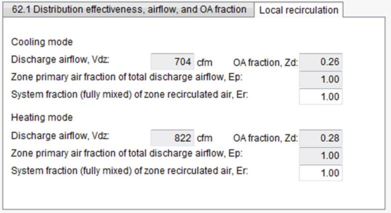
ASHRAE 62.1 Local recirculation (sub-tab)
Note that ASHRAE 62.1 Local recirculation calculations do not generally apply to fan-coil units and similar fan-powered terminal units in the context of dedicated outdoor air systems (DOAS), and thus the ApacheHVAC default for DOAS is to exclude this section of 62.1. If, however, a fan-powered terminal unit draws a significant fraction of air for recirculation either from a common return/exhaust air plenum or from a space that is over ventilated relative to 62.1 requirements, the 62.1 Local recirculation calculations may be applicable even if it is served by a DOAS.
ASHRAE 62.1 Local recirculation for Cooling mode
Discharge airflow (Vdz )
{derived per A62.1 calculation requirements; uneditable.}
OA fraction (Zd)
{derived per A62.1 calculation requirements; uneditable.}
Zone primary air fraction of total discharge airflow (Ep )
{derived per A62.1 calculation requirements; uneditable.}
System fraction (fully mixed) of zone recirculated air (Er )
{optional user input; see A62.1 requirements.}
ASHRAE 62.1 Local recirculation for Heating mode
The 62.1 Local recirculation parameters for Heating mode are a duplicate of the Cooling parameters above. The results of these calcs differ because local recirculation may be used only in either cooling or, more often, heating. Even when there is local recirculation for both modes (and the system is not a DOAS), and because the values for may differ between operating modes.
Ventilation requirement
The bottom of on the left side of the Zone Ventilation & Exhaust tab includes three related parameters on one line:
-
Ventilation req. is the Zone ventilation overall requirement accounting for all settings (see above and make-up air options).
-
Increase % can be edited as a zone-level parameter and its influence on the resulting Max req. parameter can be seen here.
-
Max req. is the
Ventilation req. after accounting for the
Increase %, and is the same as the l/s (cfm) value for
Zone ventilation max/total req. on the Zone Airflows, Turndown, & Engineering Checks tab.
Ventilation req: [ ] Derived zone value for use in system-level calculations in keeping with the setting for ‘Basis of zone outdoor air requirement’ and other active settings:
-
When set to ‘ASHRAE 62.1’, ‘OA requirement’, or ‘ASHRAE 170’, display the calculated or user-input zone value from just the one of these three methods that is selected (the other two should be disabled);
-
When engaged, the ‘Outdoor air-change req.’ and/or ‘Outdoor air percentage requirement (min % of air to zone)’ parameters always have the ability to force this value higher, as if the ‘Basis of zone outdoor air requirement’ were set to ‘Maximum’.
-
The calculated ventilation rate value for this parameter can be forced to be at least equal to the exhaust rate if the check box to ‘Force zone outside-air ventilation requirement ≥ exhaust rate’ is checked.
-
When set to ‘Maximum’, this field should display the maximum of all calculated or user-input values for zone outside air ventilation (all methods will be enabled, but the user does not need to set all of them);
-
When set to ‘Sum’, add up all of the calculated or user-input values for zone outside air ventilation (all methods will be enabled, but the user does not need to set all of them) and display the sum total here. For example, the user could enter requirements based upon number of occupants and zone floor area; this option would add the two resulting values.
-
When ASHRAE 62.1 calculations are active:
o ‘ASHRAE 62.1’ – use the greater of the two values for Cooling vs. Heating mode Zone outdoor airflow Voz ;
o ‘Maximum’ – use the greater of the two values for Cooling vs. Heating mode Zone outdoor airflow Voz as well as any other relevant/active settings, such as ‘Outdoor air-change req.’ or ‘Outdoor air percentage requirement (min % of air to zone)’.
o ‘Sum of specified requirements’ – add only the greater of the Cooling vs. Heating mode Zone outdoor airflow Voz to the other relevant/active settings (i.e., do not add both heating and cooling values when using this option).
-
When DCV is enabled , s ee Demand-controlled ventilation (DCV) section below.
Increase
[ ] % {Increases zone Ventilation req. by the user-entered percentage and reports the product as Max req. on this tab and “ Zone ventilation max/total req ” row of ventilation results matrix on the Zone Airflows, Turndown, & Engineering Checks tab
Note: Whereas the former spec for system-level application of the Increase % parameter stated that when “Basis for system outdoor air requirement” is set to “ASHRAE 62.1-2013,” checking the box for “Increase ventilation by fixed percentage for all zones” should also increase the value for “System minimum outdoor air intake, Vot” by the specified percentage (in addition to increasing the value for “Zone ventilation max/total req” for all zones by the same specified percentage), it has been deemed more appropriate that the zone-level ‘Increase’ (%) value should influence only the zone-level requirements. If the user wishes to have the system min value adjusted by that amount, they should use ‘Sum of zones’ as the “Basis for system outdoor air requirement”.
Max req
[ ] l/s {= MAX((Ventilation req. + Ventilation req. x (Increase %/100)), EA flow rate - Transfer Air flow rate)
Because it accounts for the Increase % input, this is now equivalent to “Zone ventilation max/total req” l/s (cfm) column. }
Air-change requirements, exhaust, and transfer air
ASHRAE 170 function category
[ ] {Categories from ASHRAE 170 Table 7-1.}
-
The drop-down menu selection of an ASHRAE std. 170 Functional Category should be enabled when either ASHRAE 170 or Maximum method is selected as basis for zone and system OA.
-
Set the following parameters based on A170 space function menu selection using a look-up table. Some space functional categories will require settings for all four parameters, but more often just one or both of the first two will be required:
o Minimum Outdoor ach {set ‘Zone outdoor airflow requirement’ to required ach value}
o Minimum Total ach {set ‘Primary air-change requirement’ to required ach value}
o All Room Air Exhausted Directly to Outdoors {when required, set ‘Exhaust air-change req.’ to “= SA cfm”
o Negative Pressure Relationship to Adjacent Areas {when required, selects make-up air radio button option to ‘Transfer air makes up difference between EA and SA air flows’; and sets min EA = SA +1 cfm to ensure EA > SA}
o Zone RH requirement {when required, set ‘Zone RH high limit…’ and/or ‘Zone RH low limit’ values}
-
The controls for max zone RH are in nearly all ApacheHVAC prototype systems (no change needed). Min RH requires a system with evap/spray or steam humidification. This can be added to most any system type.
-
The tables included in
Appendix E: Tables from ASHRAE 170 Ventilation for Healthcare at the end of this spec provide the requirements for the four settings above for a range of standard 170 healthcare space function categories.
-
When A170 is used to determine zone primary air-change and OA air-change rates, either the system min OA needs to be the sum of these A170 zone values or use 62.1 calcs for the system minimum, treating the A170 zone values as 62.1 Voz values. These two options are presented to the user as the system-level ‘Basis for system outdoor air requirement’ on the ‘System Parameters’ tab.
Primary air-change requirement
[ ] [ ach | l/s | l/s.m2 | l/s.pers ▼ ] [ ] l/s {overrides design airflow calcs, if greater}
Nighttime setback percentage of req. primary airflow
[ ] % {provides value for use in specialized time switch controller; the controller value provided by this is the user-input percentage of the flow rate value immediately above; enable when CAV airflow – nighttime setback parameter link is present in the network.}
Exhaust air-change requirement
[ ] [ ach | l/s | l/s.m2 | l/s.pers | l/s.unit | l/s = SA | l/s > SA | % > SA ▼ ] [ ] l/s
{default = unchecked box. The checking and setting of this parameter needs to be tied to PRM Nav settings (two-way relationship) for exhaust requirements (uses a subset of same settings, incl. ASHRAE options in next line of UI below).
When ‘l/s.unit’ is selected, the input field is for the airflow rate (l/s) per unit, and the number of units field at the end of the next line (A62.1 EA occ.) is enabled, thus determining the derived total EA rate for the zone (l/s/) at the end of this line.
When “l/s = SA” is selected, the field to left of units selector is read-only, and EA flow rate in both fields on this line should be set to the max design SA flow set or calculated in this dialog.
When “l/s > SA” is selected, input field is used for the l/s greater than the SA flow, and the derived EA flow rate to the right of the drop-down will be the sum of SA airflow as set or calculated in this dialog, plus the additional user-specified l/s. “l/s > SA” is incl. per hospital req. for “Exhaust Air Offset”—e.g., EA flow rate = SA + 300 cfm (typical values). For this option, disable “Make-up air is 100% primary air (constrained min SA flow rate),” as that would create a circular reference.
When “% > SA” is selected, input field is used for the % greater than the SA flow, and the derived EA flow rate to the right of the drop-down will be the sum of SA airflow as set or calculated in this dialog, plus the user-specified % of this value. For this option, disable “Make-up air is 100% primary air (constrained min SA flow rate),” as that would create a circular reference.
Note: SA = Primary Air. In all cases with non-zero exhaust airflow, the total of min primary and transfer air must be >/= exhaust.
ASHRAE 62.1 EA occupancy:
[Toilets – public ▼ ] [ 2 ] units
Checked box enables drop-down menu AND causes the box for ‘Exhaust air-change requirement’ above to be forced-ticked and the option for unit type automatically set. Drop-down menu options are from A62.1 Table 6-4, as included below in this section.
· Given the default of ‘Toilets – public, this will automatically set make-up air to 100% Transfer and will check the box for ‘Zone air supply is 100% transfer air (RA path, but no primary air supply)’. The user will be asked to confirm this via the following pop-up dialog:
This ASHRAE 62.1 EA category normally uses 100% transfer air.
Would you like to switch make-up air options accordingly?
WARNING: To avoid an error condition, any zone with 100% transfer
air for EA make-up must have a ventilation requirement of 0 cfm or
l/s, per ASHRAE Occupancy Category or other appropriate settings.
[ Yes ] [ No ]
'No' is the highlighted default button to encouraged reading the warning before clicking 'Yes'.
-
Most selections set ‘Exhaust air-change requirement’ parameter above in terms of l/s-m2 (cfm/ft2), and therefore must set unit type to l/s-m2 and enter l/s-m2 value in the first field and then derive l/s value, based upon the zone area, for second field.
-
Three of the selections in this drop-down menu set Exhaust air-change req. in terms of number of units (e.g., # of toilets), which requires the ‘units’ field to be enabled (default=1 unit if ‘Private…’ default=2 units if ‘Public…’). The units for Exhaust air-change req. must be automatically set to ‘l/s.unit’ and the first field must display the required A62.1 l/s.unit value, then derive the value for total in the next field based upon the number of units (toilets, etc.).}
-
Where last column of A62.1 Table 6-4 indicates ‘Y’ for 100% Transfer Air, auto-select ‘Make-up air is 100% transfer air’ below, else auto-select ‘Make-up air is 100% primary air’. Treat this as a revised default, allowing user to change it.
Force zone outside-air ventilation requirement at least equal to exhaust rate
Enabled if ‘Exhaust air-change requirement’ is checked. Default = Unchecked. Sets “OA req. as makeup for EA” on the “Zone Airflows, Turndown, & Engineering Checks” tab equal to exhaust rate; while a ventilation rate greater than this can prevail for the zone, no lesser ventilation requirement may be used in calculations.
When this box is checked, the ventilation rate calculated for the zone will be at least the exhaust rate AND will be used in system-level calculation of System Min OA (per either 62.1 or Sum of Zones).
Ticking this box disables the following:
· 2nd, 3rd, and 4th radio buttons (all but the first) immediately below;
· “Zone air supply is 100% transfer air” option below that, as these are incompatible with supplying OA ≥ EA; and
· Exhaust air-change requirement options for “l/s > SA” and “% > SA”.
For derivations of Make-up and Transfer air flow associated all radio button options below:
Exhaust air flow = derived volume flow rate for Exhaust air-change req.
Design maximum primary airflow = DOAS max primary airflow to zone when that parameter is enabled;
else the greater of Cooling maximum primary airflow and Heating maximum primary airflow parameters.
Force zone exhaust rate at least equal to outside-air ventilation requirement
The “Force zone exhaust rate at least equal to outside-air ventilation requirement” option forces EA ≥ OA. When there is no Exhaust requirement, EA = OA Max requirement for the zone. EA can thus be a non-zero value when there is no EA requirement. This is needed mainly to use EA fan to draw ventilation air into the space for spaces served by PTACs/PTHPs and can be useful for PSZ systems.
The function of forcing the make-up air source to 100% primary air (constrained min SA flow) is essential for single-zone systems, which must provide all ventilation via primary airflow. This forcing function is, however, inappropriate for PTACs/PTHPs, which generally do not provide ventilation as part of their controlled primary airflow. Forcing a relationship that treats the PTAC like a PSZ system is incorrect and could lead to incorrect terminal unit airflow sizing.
In PTACs and PTHPs such as this, make-up air is either controlled only by the EA flow rate or supply by a separate system, and we won’t know if the OA inlet is going to be left hanging as it is shown above or is going to be fed transfer air from another system.
Make-up air:
[ drop-down selector with the four options listed below as radio buttons ] [ ] %
-
100% primary air (constrained min SA flow rate) {default radio button selection; min SA for VAV ≥ EA;
Transfer = zero; All make-up air will be primary air from AHU, not transfer. }
-
100% transfer air (transfer flow rate = exhaust) {set linked “Zone/RA transfer airflow” ctrl flow = EA;
Transfer = Exhaust air flow; Transfer is 1:1 replacement for EA. }
-
Transfer air makes up difference between EA and SA air flows
Transfer = Exhaust air flow - Minimum primary airflow
-
Includes fixed percentage transfer air: [ ] % {Field for entering % value adjacent to drop-down selector is enabled when this options is selected; Zone transfer control flow = EA ´ % transfer setting. Limit user input to 99% (max value); this is technically limited to 100%, but the 100% value for this parameter is already covered by the 100% transfer option above.}
Transfer = Exhaust air flow ´ specified percentage
Make-up air requirement used in calc of Minimum primary airflow = Exhaust air flow - Transfer air flow
The four Make-up air options on the drop-down selector must be enabled only when ‘Exhaust air-change requirement’ is checked by one of three means: user mouse click; via A62.1 EA occ setting, or via selection of A170 category that requires exhaust.}
For PTACs and PTHPs (determined by all links within sys frame being inside the multiplex, but air inlets/outlets are not inside multiplex, per Configuration requirements), we should grey out the Make-up air source selector.
If there is no transfer link, then must be no possibility of a transfer value. The following make-up air options and parameters must therefore be disabled by lack of “Zone/RA transfer airflow” link:
· 100% transfer air (transfer flow rate = exhaust)
· Transfer air makes up difference between EA and SA air flows
· Includes fixed percentage transfer air
¨ Zone air supply is 100% transfer (RA path, but no primary air supply)
¨ Supply incl. transfer in addition to primary air (% > min SA)
Exhaust airflow
[ ] {Zone exhaust airflow as required by all settings above, including Exhaust air-change requirements, forcing EA at least equal to OA ventilation, which is used in the case of some PTACs and similar packaged terminal unit systems for which ventilation to the zone is driven by a local exhaust fan or ducted outlet from the space to a system exhaust fan.}
Zone air supply is 100% transfer air (RA path, but no primary air supply)
When checked, Transfer airflow value used in controller with “Zone/RA transfer airflow” link is derived as :
Transfer = Max (Design maximum primary airflow, Exhaust air flow)
Design maximum primary airflow =
DOAS max primary airflow to zone when that parameter is enabled;
else the greater of Cooling maximum primary airflow and Heating maximum primary airflow parameters.
This option is compatible with only the “ Make-up air is 100% transfer air (transfer flow rate = exhaust) ” radio button above (see mutual exclusivity rules below).
Checking this box sets “ Minimum primary airflow” and, when present, “DOAS max primary airflow to zone” = 0.00.
When the following links are not present, checking this box also sets “Cooling maximum primary airflow,” and “Heating maximum primary airflow” = 0.00:
· FCU Cooling airflow CAV/2sp/VAV
· FCU Heating airflow CAV/2sp/VAV
· PTAC/PTHP cool airflow CAV/2sp/VAV
· PTAC/PTHP heating airflow CAV/2sp/VAV
· UCS Cooling airflow
The “Cooling maximum primary airflow,” and “Heating maximum primary airflow” remain at calculated values in the context of the FCUs and PTACs, as they are the max recirculated Cooling and Heating airflow values for these terminal units. This is not the same for Active Beams, Fan-Powered Boxes (FPB), or Dual-Fan Dual-Duct (DFDD) system types: Whereas these also use recirculated airflow for space heating and/or cooling, they all depend upon the presence of primary system airflow at the zone to drive some or all aspects of space conditioning airflow.
Via the parameters above, the Max and Min flow rates for all primary airflow controls on the zone multiplex layer are set to zero—i.e., for controls with the following system parameter links:
· Cooling airflow VAV/CAV
· Heating airflow VAV/CAV
· DOAS vent airflow
· DOAS vent airflow CAV/DCV
· FPB Primary airflow CAV/VAV
· Act bm/IU Primary air CAV/VAV cool
· Act bm/IU Primary air CAV/VAV heat
· PSZ Cooling airflow CAV/2sp/VAV
· PSZ Heating airflow CAV/2sp/VAV
· Cooling-only sys airflow
· Heating-only sys airflow
· CAV airflow – occupied hours
· CAV airflow – nighttime setback
· Min fan airflow
· Zone DCV stage 1 – VAV ctrl
Mutual exclusivity rules for “Zone air supply is 100% transfer air (RA path, but no primary air supply)” parameter:
When the box for “Exhaust air-change req” has been checked above, selecting any of the three radio buttons for make-up and transfer options other than “Make-up air is 100% transfer air (transfer flow rate = exhaust)” will cause this option to be unchecked, disabled, and grayed out.
When the box for “Exhaust air-change req” has not been checked above, selecting this option causes the radio button above for “Make-up air is 100% transfer air (transfer flow rate = exhaust)” to be forced selected, and the other three radio buttons are grayed out:
a) If the user checks the box for “Exhaust air-change req” after selecting the option for “Zone air supply is 100% transfer air…”, then by virtue of the “Zone air supply is 100% transfer air…” option being checked, the selection of the four radio buttons must be constrained to the second one: “Make-up air is 100% transfer air…”.
b) This option is mutually exclusive with respect to the next option below, as it’s not possible to have zone supply air = 100% transfer while also having zone supply air = primary + transfer.
Supply incl. transfer in addition to primary air (% > min SA)
[ ] %
(as in a negatively pressurized zone) {note on dialog, as in mock-up}
{When checked, derive flow rate for “Zone/RA transfer airflow” control link as:
Transfer = Minimum primary airflow ´ % > min SA
When exhaust is specified, the following must be true (if not, increase Transfer + Minimum primary airflow until true, as in Derivation Example, below):
Transfer + Minimum primary airflow ≥ Exhaust air flow .
Exclusivity:
1. Selecting this option causes all four radio buttons for make-up and transfer options above to be disabled and grayed out grayed out—i.e., it overrides all of those options.}
This option is mutually exclusive with respect to the option immediately above, as it’s not possible to have zone supply air = 100% transfer while also having zone supply air = primary + transfer.
Derivation Example:
If the user checks this option and enters a value of 50% transfer air in addition to min primary SA volume ν , the Transfer air will be 0.5 ν and the combined total supply airflow to the zone will be 1.5 ν .
If there is no exhaust airflow, then this is simply an addition of transfer air, set relative to min primary airflow.
It also, however, raises the maximum value for exhaust airflow requirement permitted without forcing the calculated min primary flow to be raised.
· If the user first sets Transfer to 0.5 ν and then sets Exhaust airflow to 1.2 ν , there will be no change in Min primary airflow , given there is enough combined min primary airflow + transfer airflow (1.5 ν ) to make up for it.
· If the user then sets the EA flow rate to 1.8 ν , whether directly or by entering an ACH value that results in this, the additional 0.3 ν must come from somewhere.
o Without this transfer option engaged, the min primary SA flow rate would simply be increased to provide this additional amount.
o With this option set to for additional transfer = 50% of min SA, the additional 0.3 ν should be provided by raising the min primary SA to 1.8/1.5 = 1.2 ν , so that the resulting combined supply to the zone is at 1.2 ν min SA + (Transfer at 0.5*SA) = 1.8 ν minimum airflow into the zone. The effect is to proportionally increasing both min primary SA and transfer airflow, such that there is enough make-up air for the specified EA and the transfer is always 50% of min SA.}
Used for labs, hospitals, and industry where a fraction of RA must be transfer air to maintain negatively pressurized rooms.
Transfer at max EA and min primary airflow
[ ] l/s
{Derived as described below according to inputs and selection of options for transfer air, above; this is same as Transfer airflow parameter on the “Zone Airflows, Turndown, & Engineering Checks” tab:
For derivations of Transfer air flow all associated Make-up air combo-box options and check-box options noted below:
Exhaust air flow = derived volume flow rate for Exhaust air-change req.
Design maximum primary airflow =
· DOAS max primary airflow to zone when that parameter is enabled;
· else the greater of Cooling maximum primary airflow and Heating maximum primary airflow parameters.
When ventilation “Exhaust air-change req” is checked and noted Make-up air option is selected, apply the derivation listed below that Make-up air option to determine the values to displayed here and for same parameter on the Zone Airflows, Turndown, & Engineering Checks tab, and used in controller with “ Zone/RA transfer airflow ” link:
Make-up air:
· 100% primary air (constrained min SA flow rate) Transfer = zero
· 100% transfer air (transfer flow rate = exhaust) Transfer = Exhaust air flow
· Transfer air makes up difference between EA and SA air flows
Transfer = Exhaust air flow - Minimum primary airflow
· Includes fixed percentage transfer air Transfer = Exhaust air flow ´ specified percentage
Make-up air requirement used in calc of Minimum primary airflow = Exhaust air flow - Transfer air flow
When ‘ þ Zone air supply is 100% transfer (RA path, but no primary air supply)’ is checked, derive value displayed here and used in controller with “Zone/RA transfer airflow” link as:
Transfer = Max (Design maximum primary airflow, Exhaust air flow)
When ‘ þ Supply incl. transfer in addition to primary air (% > min SA): [ ] %’ is engaged, derive value displayed here and used in controller with “Zone/RA transfer airflow” link as:
Transfer = Minimum primary airflow ´ % > min SA
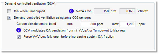
Demand-controlled ventilation (DCV)
Minimum when unoccupied
‘Minimum when unoccupied’ checkbox is enabled if either “OA min reset – Unoccupied zone” or “OA min reset – Unocc zn VAV%” link is present in the network. See Definition of two DCV-related controller applications for the four Occupancy-based DCV controller links section (four pages below) for compete logic and derivations for the occupancy-based DCV controls.
VozA / min
[ ] l/s [ ] l/s.m2
{Enabled ‘Minimum when unoccupied’ checkbox if either “OA min reset – Unoccupied zone” or “OA min reset – Unocc zn VAV%” link is present in the network. See Definition of two DCV-related controller applications for the four Occupancy-based DCV controller links section (four pages below) for compete logic and derivations for the occupancy-based DCV controls.
Enable display of VozA if either ‘Minimum when unoccupied’ or ‘Demand-controlled ventilation using CO2 sensors’ box is checked. VozA = (Ra x Az)/min(Ez_Cooling, Ez_Heating) , when basis for ventilation is ‘ASHRAE 62.1’ or ‘Maximum’, otherwise set equal to ‘Min primary airflow at turndown’; uneditable.
-
OA min reset – Unoccupied zone control allows the minimum OA ventilation rate to be reduced to just the ASHRAE 62.1
area-based minimum value for any zone with both 62.1 ventilation settings and this type of OA reset controller when the space is unoccupied.
Minimum OA value for the unoccupied zone during normal building operating hours is calculated as follows, and this results in a volume flow rate:
VozA = (Ra x Az)/min(Ez_Cooling, Ez_Heating)
where
VozA is the A62.1 area-based component of Voz. For system capable of OA reset, this is the min OA ventilation requirement for the unoccupied zone, accounting for diffuser configuration, during building operating hours.
Ra is the area-based ventilation coefficient for the A62.1 zone occupancy type.
Az is the area of the zone.
Ezmin is the minimum zone-level distribution effectiveness for Cooling and Heating modes.
When Basis for zone OA requirement is not ASHRAE 62.1, the value for the “Min primary airflow or VAV turndown” parameter is used in place of VozA.
-
The
OA min reset – Unocc zn VAV% control votes on the reset of the system-level OA % when the zone is Unoccupied during building operating hours (OA fraction at VAV flow rate per 62.1 area-based Ra/Ez calc).}
Controller gets four values based upon the ASHRAE 62.1 area-based minimum value calculated immediately above.
o System OA required at Max zone flow (%)
= (Zone floor area ´ Ra/Ez) / Max zone VAV primary airflow rate ´ 100
o System OA required at Min zone flow (%)
= (Zone floor area ´ Ra/Ez) / Min zone VAV primary airflow rate ´ 100
o Zone VAV sensed flow Midband (cfm)
= Max zone VAV primary airflow rate - (0.5 ´ sensed flow Bandwidth)
o Zone VAV sensed flow Bandwidth (cfm)
= Max zone VAV primary airflow rate - Min zone VAV primary airflow rate
When Basis for zone OA requirement is not ASHRAE 62.1, the value for the “Min primary airflow or VAV turndown” parameter is used in place of VozA.
The latter two of these values are the same as for the MC18: System OA reset based on zone VAV flow fraction controller values presently calculated in columns DB and DC on the Sys 5,7 tab of the Loads Data Spreadsheet. The first two are similar to the corresponding MC18 values for, but use just the area-based minimum ventilation rate, rather than the overall 62.1 requirement.
Demand-controlled ventilation reduction when zones are unoccupied (typically only when this occurs during normal building operating hours) allows for the OA ventilation rate to be reduced to the ASHRAE 62.1 area-based minimum value VozA = (Ra ´ Az / Ez) for a zone with both 62.1 ventilation settings and an appropriate OA reset controller.
When Basis for zone OA requirement is not ASHRAE 62.1, the value for the “Min primary airflow or VAV turndown” parameter will be used in place of VozA.
The “OA min reset – Unoccupied zone” controller is normally used to reset a zone-level ventilation rate for a zone served by a dedicated outside air system (DOAS) or a zone on a VAV system when that system is operating in 100% OA economizer mode.
The “OA min reset – Unocc zn VAV%” controller provides the zone-level vote for modulating the system-level OA minimum in the context of a VAV system with OA fraction continuously reset at the air handler based upon zone VAV flow fractions (equivalent to zone VAV damper positions).
See also supplemental section: Definition of DCV-related controller applications.
Demand-controlled ventilation using CO2 sensors
{default = unchecked; enabled if CO2-based DCV controls—any one or more of the links with CO2 Concentration indicated as sensed variable—are present in HVAC network. These links and associated default checkbox state are summarized as follows:
CO2-based
· DOAS vent airflow CAV/DCV {used on zone ventilation flow path in DOAS systems; modulation options are relevant}
· Zone DCV stage1 – VAV ctrl {used on zone VAV primary air flow path in VAV systems; modulation options not relevant}
· OA min reset - zone CO2 {used for system OA damper percentage flow control in VAV or similar multi-zone with a system recirculation path; normally used with Zone DCV stage1 – VAV ctrl.}
· Airflow ON if NV insuf vent {used on zone VAV primary air flow path in mixed-mode Nat-Vent/VAV systems; based on CO2 exceeding threshold, this controller provides a logical OR signal to re-enable the standard VAV controller}
· OA min reset - Occupied zone CO2 {used in place of standard “DOAS vent airflow CAV/DCV” link on ventilation flow path in DOAS systems (controlled variable = flow rate); Zone Occupancy Profile (else PP2); See derivations on p.53}
Non-CO2-based
· OA min reset - Unoccupied zone {used in tandem with “OA min reset - Occupied zone CO2” link on ventilation flow path in DOAS systems}
· OA min reset – Occupied zn VAV% {used in place of “OA min reset - zone CO2” link on OA damper percentage flow control in VAV or similar multi-zone with a system recirculation path}
· OA min reset – Unocc zn VAV% {used in tandem with “OA min reset - zone CO2” link on OA damper percentage flow control in VAV or similar multi-zone with a system recirculation path}
This controls modulated airflow in proportion to sensed CO2 or occupancy > 0 (representing occupancy sensor). The particular application-specific link determines whether this is zone ventilation airflow, as in a DOAS, the zone VAV box in a VAV system, or the system outside air damper min OA value in any non-DOAS multi-zone variant of a VAV system.
The derived for the values for the controlled variable---air flow rate---to be used at min and max sensed CO2 values are described below the two DCV modulation check-box options with respect to each of the noted parameter links, the CO2 ppm min & max inputs, and the two modulation options.
When DCV is enabled and “DCV modulates OA ventilation below (up to) setpoint/requirement” [default option] is selected, the DCV airflow control will modulate the zone OA from a reduced minimum up to the zone setpoint/requirement.
-
When the ‘Basis for zone outside air requirement’ is set to either ASHRAE 62.1 or Maximum, the reduced minimum should be the value for VozA.
o This is equivalent to checking the box for DCV ‘Minimum when unoccupied’. Therefore:
-
When ‘Basis for zone outside air requirement’ is A62.1 (but not when basis is set to Max), checking the box for DCV ‘Minimum when unoccupied’ should cause the box for DCV modulates OA ventilation below (up to) setpoint/requirement to also be checked, but not the other way around. In other words, there is a one-way link driven by ticking the box for DCV ‘Minimum when unoccupied’, but unchecking this box or separately checking the DCV modulates OA ventilation below (up to) setpoint/requirement box should not cause any linked behavior.
-
When the ‘Basis for zone outside air requirement’ is set to anything other than ASHRAE 62.1 or Maximum, the reduced minimum is determined by the user setting for ‘Min primary airflow or VAV turndown’.
This will allow a controller with OA min reset – Occupied zone CO2 link to behave the same as with DOAS vent airflow CAV/DCV link when there is no “occupancy sensor” in the zone.
Note 1: So long as the CO2 values are set appropriately, the outcome for the modulated flow rate should be the same when the zone is unoccupied (i.e., when there are no occupants to generate CO2). Therefore, this minor conflict needs to be addressed mainly as a matter of the UI correctly indicating which controls are in play.
Note 2: Checking the box for Demand-controlled ventilation (DCV) via zone CO2 sensors when the box for DCV ‘Minimum when unoccupied’ is already checked should cause the box for DCV modulates OA ventilation below (up to) setpoint/requirement to also be checked. Again, this is a one-way, top-down linkage. This requirement, however, does not need to be stated, as it is actually redundant (and consistent with) the requirement that DCV modulates OA ventilation below (up to) setpoint/requirement should be checked as the initial default option whenever Demand-controlled ventilation (DCV) via zone CO2 sensors is first checked by the user or by the presence of a link that causes it to be checked. }
Carbon dioxide control band
min: [ ] ppm max: [ ] ppm
{zero d.p.; grey out if CO2-based DCV controls not present in HVAC system network OR when tick box above is un-checked}
DCV modulates OA ventilation below (up to) setpoint/requirement {As the ventilation modulation alternative to this was eliminated, this label has been retained on the UI only to indicated what DCV will do. The calculated A62.1 zone requirement or other OA requirement is the max design OA value. Modulation is from a reduced minimum (VozA or user setting for ‘Min primary airflow at turndown’) up to the max design OA for the zone. See application details below.}
For DOAS (100% OA systems), when a zone has CO2-based DCV engaged and ventilation requirement set using ASHRAE 62.1, min primary airflow is set to VozA. This is the building component (Ra x Az)/Ez of A62.1 zone ventilation (Voz). When the basis for the zone ventilation is other than ASHRAE 62.1, the value for “Min primary airflow at turndown” on the Zone Airflows, Turndown, & Engineering Checks tab is used in place of VozA.
The VozA minimum OA value is also used to determine the zone “vote” for resetting of the system min OA primary airflow in recirculating VAV systems when the “OA min reset” controller link is in place and DCV is engaged for a zone. In this case, the system minimum OA percentage in the primary supply airflow volume is modulated according to the highest zone vote. When a zone with CO2-based DCV is at or below the minimum specified CO2 value, the zone will request only enough OA in the primary air to provide the VozA volume of OA at the current zone VAV box position.
The maximum zone OA volume (controlled directly in a DOAS with DCV and requested in a VAV system with DCV) will be the ASHRAE 62.1 or other OA requirement/setpoint on this tab, including any OA requirement added by entering a value for “Increase” (%).
Force VAV box fully open before increasing system OA fraction
Enabled and checked by default when “Zone DCV stage1 – VAV ctrl” link is present AND Demand-controlled ventilation (DCV) via zone CO2 sensors is checked, above .
Zone DCV stage1 – VAV ctrl controller link
· Used in VAV systems to force zone primary air flow VAV box more fully open as CO2 rises; DCV modulation options are not relevant; upgrade to this from MC11 in Sys 05/07.
· Normally used as first stage of control in conjunction with (followed by) OA min reset - zone CO2 controller link .
· When ¨ Force VAV box fully open before increasing system OA fraction is checked:
o Flow Rate values at Min and Max signal (sensed variable) are set as follows:
o Flow Rate at Max signal = Cooling maximum primary airflow
o Flow Rate at Min signal = Minimum primary airflow
o CO2 midband (ppm) = CO2 control band min + 0.25(CO2 control band max – min)
o CO2 bandwidth (ppm) = 0.5(CO2 control band max – min)
o Else set both Flow Rate at Max signal and Flow Rate at Min signal = 0; midband & bandwidth can remain.