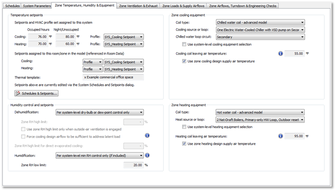
Zone Temperature, Humidity, & Equipment tab
Temperature setpoints
Setpoints and HVAC profile set assigned to this system:
For ISM phase 1, the Setpoints displayed are an uneditable copy of settings in the System Schedules and Setpoints dialog. The relevant setpoints are taken from the Mon-Fri profile, and as a proxy for occupied hours, selected the based upon the following criteria:
· For XXXX SYS_Cooling Setpoint, the Minimum value in the profile (lowest cooling setpoint will occur during occupied hours).
· For XXXX SYS_Heating Setpoint, the Maximum value in the profile (highest heating setpoint will occur during occupied hours).
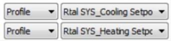
The profile name displayed is the HVAC profile set assigned to the system—e.g., SYS_Cooling Setpoint.
Profile names displayed here are from one of two possible sources:
· The default profiles (SYS_Cooling Setpoint and SYS_Heating Setpoint) with which all other HVAC profiles are coordinated for any HVAC network loaded form the HVAC Systems Library;
· A different pair of heating and cooling setpoint profiles that have subsequently been defined by and assigned to the HVAC network by the use of the System Schedules and Setpoints dialog, such that they are also coordinated with a full set of HVAC profiles sharing the same user-added prefix.
If other profiles are manually assigned to any or all components and controllers, which is permissible, these profiles will be ignored.
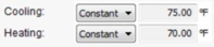
Setpoints assigned to this room/zone in the model (referenced in Space Data)
↔
The display of “Constant” or “Profile” and Space Data setpoints vs. profile name reflects the HVAC profile set assigned in Space Data. The setpoints above are firstly taken from Space Data, then (for ISM phase 1) edited via the System Schedules and Setpoints dialog, wherein new named setpoint profiles can be set up.
Thermal Template
This is the name of thermal template assigned to principal room on current layer. It is for information only.
Schedules & Setpoints… button
The ‘Schedules & Setpoints…’ button opens the System Schedules & Setpoints dialog, just the same as the toolbar button, but without closing the System Parameters dialog. This will be removed in ISM phase 2.
Humidity control and setpoints
Dehumidification
Options:
· per system-level dry-bulb or dew-point control only
· system supply air conditioned per zone RH sensors
The “system supply air conditioned per zone RH sensors” option is enabled and set it as the default if Cooling coil – AHU dehum LAT, Cool coil – AHU extend dehum LAT, Cooling coil – full dehum LAT band, or Cooling coil – full h/c/dehum LAT link is present in the system frame, otherwise, the first option is the only possibility. If one of these links is present, and the setting is then changed to “per system-level dry-bulb or dew-point control only”, the Time Switch Profile in a controller with one of these links is set to “OFF continuously”, and set back to “ON continuously” if the user subsequently changes to the drop-down setting to “system supply air conditioned per zone RH sensors”.
Zone RH high limit
Enabled and editable when Dehumidification drop-down above is enabled AND set to “ system supply air conditioned per zone RH sensors ”; default = max % RH from Space Data, else 60%. For all links, the default proportional bandwidth is 10%, thus the controller Midband is set to ‘Zone RH high limit’ - 5%.
þ Use zone RH high limit only when outside-air ventilation is engaged
Enabled when Dehumidification drop-down above is enabled AND set to “ system supply air conditioned per zone RH sensors ”; checked by default. When Dehumidification is set to “system supply air conditioned per zone RH sensors” AND this box is checked, the linked controller Time Switch profile is set to HVAC EP1 - Economizer (Timeswitch: Sys 3--8).
þ Force cooling design airflow to be sufficient to address latent load
A supply airflow requirement will be calculated using the zone latent load shown on the Zone Loads & Supply Airflows tab and the zone relative humidity and dry-bulb temperature setpoints on this tab to determine the room humidity ratio, plus the System cooling coil min LAT for dehumidification on the System Parameters tab to determine the supply air humidity ratio (assuming saturated air at 100% RH leaving the cooling coil at the min LAT). The required airflow to meet the latent load is then determined by the latent load divided by the absolute humidity difference between the room and supply air.
If the airflow required to address the latent load is greater than that required to address the sensible load, the Cooling design max airflow will be set to the larger of the two calculated airflows when this check box is ticked.
This check box is linked to a duplicate of the same parameter on the Zone Loads & Supply Airflows tab.
Zone RH high limit for Direct Evap Cooling
Enabled if Zone RH high-limit for DEC link is present; assuming a 4% Deadband, the linked dependent controller Setpoint = ‘Zone RH high limit’ + 2% .
Humidification:
Options:
· per system-level min RH control only (if included)
· system supply air humidified per zone RH sensors
Enabled and set by default to “ system supply air humidified per zone RH sensors ” option if Evap/spray humid per Zn RH or Steam humid per Zn RH link is present, otherwise the first option is the only possibility; If one of these links is present, but the user changes to setting to “per system-level RH control only…”, the Time Switch Profile in the linked controller is set to “OFF continuously,” and is set back to “ON continuously” if the user changes to the setting to “system supply air humidified per zone RH sensors.”
Zone RH low limit
The Zone RH low limit input below applies only when humidification of system air is controlled according to zone-level sensors; thus setting the drop-down selector here to “per system-level min RH control only (if included)” simply disables the feedback from the currently selected zone(s). Any zone without a set RH low limit will still receive system-level humidification that is either controlled according to sensors in other zones on the same system or is controlled only according to the minimum RH of the system supply air.
System-level settings for control of system supply air minimum RH (requiring appropriate time switch controller with RH parameter link and controlled humidification source) are located on the System Parameters tab.
Enabled with default of 20% if Evap/spray humid per Zn RH or Steam humid per Zn RH link is present AND Humidification is set to “system supply air humidified per zone RH sensors”
Zone cooling equipment
Coil type
Sets this parameter in coil dialog for a zone-level cooling coil. Enabled if “FCU/act-beam cool coil” or “PTAC/PTHP cooling coil” link is present. Options are the same as those in the coil dialog.
Cooling source or loop
Sets this parameter in coil dialog for a zone-level cooling coil. Enabled if “FCU/act-beam cool coil” or “PTAC/PTHP cooling coil” link is present. Options are the same as those in the coil dialog, consistent option selected above for coil type.
Chilled water loop circuit
Sets this parameter in coil dialog for a zone-level cooling coil. Enabled if “FCU/act-beam cool coil” or “PTAC/PTHP cooling coil” link is present. Options are the same as those in the coil dialog, consistent option selected above for ‘Cooling source or loop’.
þ Use system cooling plant selection to set terminal units and equip.
Options for ‘Coil type’, ‘Cooling source or loop’, and ‘Chilled water loop circuit’ above will be set consistent with the system-level coil for the air-handling unit, as given on the ‘System Parameters’ tab.
Cooling coil leaving air temperature
þ Use zone Cooling design supply air temperature
When this box is checked, as it is by default, the otherwise editable field for ‘Cooling coil leaving air temperature’ is a copy of the value for ‘Cooling design supply air temperature’ on the Zone Loads & Supply Airflows tab.
For packaged single-zone systems and packaged terminal units, zone equipment parameters are included under ‘Primary air section’ on the ‘System Parameters’ tab.
Zone heating equipment
Coil type
Sets this parameter in coil dialog for a zone-level heating coil. Enabled if “FCU/act-beam heat coil” or “PTAC/PTHP heating coil” link is present. Options are the same as those in the coil dialog.
Heating source or loop
Sets this parameter in coil dialog for a zone-level heating coil. Enabled if “FCU/act-beam heat coil” or “PTAC/PTHP heating coil” link is present. Options are the same as those in the coil dialog, consistent option selected above for coil type.
Hot water loop circuit
Sets this parameter in coil dialog for a zone-level heating coil. Enabled if “FCU/act-beam heat coil” or “PTAC/PTHP heating coil” link is present. Options are the same as those in the coil dialog, consistent option selected above for ‘Heating source or loop’.
þ Use system cooling plant selection to set terminal units and equip.
Options for ‘Coil type’, ‘Heating source or loop’, and ‘Hot water loop circuit’ above will be set consistent with the system-level coil for the air-handling unit, as given on the ‘System Parameters’ tab.
Heating coil leaving air temperature
þ Use zone Heating design supply air temperature
When this box is checked, as it is by default, the otherwise editable field for ‘Heating coil leaving air temperature’ is a copy of the value for ‘Heating design supply air temperature’ on the Zone Loads & Supply Airflows tab.
For packaged single-zone systems and packaged terminal units, zone equipment parameters are included under ‘Primary air section’ on the ‘System Parameters’ tab.