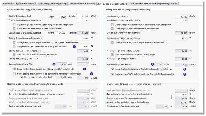
Zone Loads & Supply Airflows tab
Cooling loads and air supply for space conditioning
Cooling design zone load
Latent: [ ] kW Sensible: [ ] kW {both values sized by Room/zone Loads run; editable}
Cooling design load oversizing factor
[ ] {range = 0.1 to 10.0; default = 1.0}
Adjust design load to match user setting for SA fan design flow
{Enabled only when ‘Override (disable) fan autosizing’ box is checked in the ‘Primary air section’ frame on the System Parameters tab. Checking the “Adjust…” box makes the zone Cooling design load oversizing factor on the line above an uneditable derived value = SA Fan Design Flow / Autosized System SA flow, subject to the constraint that this value must be >/= 1.0 (i.e., rounded up to 1.0) if the checkbox for “Allow undersizing of zone airflows as a result of design load adjustment” is not ticked. When “Allow undersizing…” is checked, then the “Cooling design load oversizing factor” is permitted to be < 1.0.
Note: This feature may result in a system with excessive zone min flow rates. When the box for “Allow undersizing…” is also checked, derived airflow may be less than required by the calculated peak loads for the zone, potentially resulting in unmet load hours.
*This checkbox will be replaced in ISM 1b with a checkbox for adjusting the design airflow, rather than the load.
Allow undersizing of zone airflows as result of design load adjustment
Allow a loads “oversizing” factor less than 1.0 only if the user has ticked this box. This feature may lead to insufficient maximum flow rates and unmet load hours.}
*This checkbox will be replaced in ISM 1b with a checkbox for adjusting the design airflow, rather than the load.
Design load with oversize/adjustment
Latent: [ ] Sensible: [ ] kW {both adjusted per same oversizing adj. factors}
Cooling design supply air temperature
[ ] °C
Use system (AHU or single-zone) min SAT on System Parameters tab
1. When checkbox is unticked (default state), use design SAT entered above both for setting ventilation supply air temperature, when included in Room Loads, and for calculating design airflows below.
When check box is ticked, the value displayed is an uneditable dynamic copy of “System min SAT for space cooling & vent tempering:” parameter on the System Parameters tab.}
Check box is forced ticked when the system type is single-zone (all links in the system frame are within the multiplex, as in prototype system types 01–04); otherwise un-ticked by default.
Check box is un-ticked and disabled when either “DOAS vent airflow” or “DOAS vent airflow CAV/DCV” parameter link is present }
Use percent of SAT reset delta for cooling airflow sizing
[ ] % { Mutually exclusive: Only this or the checkbox for parameter immediately above can be checked at any given time. When checked, force the Use system (AHU or single-zone) min SAT… check box immediately above to also be ticked, and multiply the System SAT reset value on the SP tab by the percentage entered here, then add the resulting temperature delta to the Cooling design supply air temperature above. Example: if the System min SAT is 55 F with 10 F SAT reset and the user checks this box and enters 80%, the 55 + (0.8 x 10) = 63 F Cooling design supply air temperature; Revise the Cooling design supply air temperature displayed above accordingly; check box is un-checked by default; the default value = 70%, otherwise set by user for interior zones as required by Title-24 (70%) and other codes (100%).}
i Info button note: Use for lightly loaded zones or zones with relatively constant loads, such as interior zones or those used for telecom, etc., as described in ASHRAE std. 90.1 and required by CA Title-24 to avoid undercooling such zones if SAT reset is based upon outdoor temperature and to ensure the system reset will occur as intended when controlled according to zone cooling demand.
Cooling design zone air temperature
[ ] °C
þ Use zone thermostat temperature setpoint(s)
{forced ticked for ISM phase 1, thus field above is uneditable for phase 1}
Cooling design supply air delta-T
[ ] K {derived from the two values immediately above it}
Cooling design maximum airflow
[ ] l/s [ ] l/s.m2
{Derived from loads and supply air temperature as determined by settings above in this dialog; spell out whole word “maximum”.}
Cooling design maximum airflow accounts for all of the parameters listed below:
· Airflow required to meet sensible cooling load (calculated according to the following):
o Cooling design sensible load, with any oversizing and/or adjustment applied
o Cooling design supply air temperature
o Cooling design zone air temperature
o Derived cooling design supply air delta-T
· Forcing of cooling primary air at least equal to ventilation rate (optional; checked by default; disabled if DOAS).
o When checked, cooling design maximum airflow will be increased if necessary to be at least equal the value for “Zone ventilation max/total req” l/s (cfm) column on the Zone Airflows, Turndown, & Engineering Checks tab.
· Airflow sufficient to meet Cooling design latent load;
o When either “Force cooling design airflow to be sufficient to maintain zone RH setpoint” is checked on this tab or “Force cooling design airflow to be sufficient to address latent load” is checked on the Zone Temp, Humidity, Equipment tab, the cooling design maximum airflow value will be the greater of that required to address the sensible or latent loads. This includes any oversizing and adjustments applied.
Force cooling design max airflow at least equal to ventilation rate
Checked by default.* This option forces the maximum airflow for cooling (below) to be at least equal to the “Zone ventilation max/total req” l/s (cfm) column for the same zone.
Disabled if FCU Cooling airflow CAV/2sp/VAV link is present.
This option will override the load-based calculation of design maximum cooling airflow, if necessary, to ensure it is at least equal to the required ventilation airflow. The same option is available separately for design maximum heating airflow.
The alternative option provided on the Zone Airflows, Turndown, & Engineering Checks tab to "Force overall max airflow at least equal to required ventilation rate" will, if needed, adjust only the larger of the two design maximum airflow values (heating or cooling), but not both.
Force cooling design airflow to be sufficient to maintain zone RH setpoint
Default = unchecked. This option causes the maximum airflow for cooling to use the larger of the requirements calculated just for sensible loads, as is most typical, or for latent loads, as described below. Disable when dehumidification option is set to ‘Per system-level dry-bulb or dew-point control only’.
Airflow required to meet latent load
[ ] % {The info button text below provides a succinct summary of how this is calculated. The key will be call a bit of code from the newly developed psych chart tool to determine the humidity ratio.
A supply airflow requirement will be calculated using the zone latent load shown above, the zone relative humidity and dry-bulb temperature setpoints on the Zone Temp, Humidity & Equipment tab to determine the room humidity ratio, plus the System cooling coil min LAT for dehumidification on the System Parameters tab to determine the supply air humidity ratio (assuming saturated air at 100% RH leaving the cooling coil at the min LAT). The required airflow to meet the latent load is then determined by the latent load divided by the absolute humidity difference between the room and supply air.
If the airflow required to address the latent load is greater than that required to address the sensible load, the Cooling design max airflow will be set to the larger of the two calculated airflows when this check box is ticked.
This check box is linked to a duplicate of the same parameter on the Zone Temp, Humidity & Equipment tab.
The airflow (cfm) required to address the latent load is given by for following equation:
CFMLATENT = QLATENT / 4840 x (WROOM - WSUPPLY)
where QLATENT is the space latent heat gain, 4840 is a conversion factor, and WROOM and WSUPPLY are the humidity ratios (lbs. H2O per lb. Dry Air) for the room and supply air, respectively.
Humidity Ratio (W) is the ratio of the mass of water vapor in a given air sample to the mass of dry air in the same sample. In IP units, Humidity ratio is measured in units of pound-mass of water per pound-mass of dry air. By multiplying by 7000 [grains per pound-mass], this value may be expressed in grains of water per pound-mass of dry air. W = mw / ma = 0.62198 Xw / Xa = 0.62198 pw / (p - pw)
Heating loads and air supply for space conditioning
Heating design zone load
[ ] kW set by Room/zone level autosizing; editable.
Heating design zone load
[ ] kW set by Room/zone level autosizing; editable.
Heating design load oversizing factor
[ ] range = 0.1 to 10.0; default = 1.0
þ Adjust design load to match user setting for SA fan design flow
{Enabled only when ‘Override (disable) fan autosizing’ box is checked in the ‘Primary air section’ frame on the System Parameters tab. Checking the “Adjust…” box makes the zone Cooling design load oversizing factor on the line above an uneditable derived value = SA Fan Design Flow / Autosized System SA flow, subject to the constraint that this value must be >/= 1.0 (i.e., rounded up to 1.0) if the checkbox for “Allow undersizing of zone airflows as a result of design load adjustment” is not ticked. When “Allow undersizing…” is checked, then the “Cooling design load oversizing factor” is permitted to be < 1.0.
Note: This feature may result in a system with excessive zone min flow rates. When the box for “Allow undersizing…” is also checked, derived airflow may be less than required by the calculated peak loads for the zone, potentially resulting in unmet load hours.
*This checkbox will be replaced in ISM 1b with a checkbox for adjusting the design airflow, rather than the load.
þ Allow undersizing of zone airflows as result of design load adjustment
Allow a loads “oversizing” factor less than 1.0 only if the user has ticked this box. This feature may lead to insufficient maximum flow rates and unmet load hours.}
*This checkbox will be replaced in ISM 1b with a checkbox for adjusting the design airflow, rather than the load.
Design load with oversize/adjustment
[ ] kW {both adjusted per same oversizing adj. factors}
Heating design supply air temperature
[ ] °C
þ Use system (AHU or single-zone) heating coil max LAT
Behavior as follows:
1. When unchecked (default state), use design SAT both for setting ventilation supply air temperature, when included in Room Loads, and for calculating design airflows below.
When check box is ticked, value displayed is uneditable dynamic copy of “System min SAT for space cooling & vent tempering”.
When system configuration is single-zone, value displayed is uneditable dynamic copy of “Heating mode max SAT” on System Parameters tab and checkbox is forced ticked; otherwise un-ticked by default.
Check box is forced un-ticked when either “DOAS vent airflow” or “DOAS vent airflow CAV/DCV” parameter link is present.
Heating design zone air temperature
[ ] °C
þ Use zone thermostat temperature setpoint(s)
{forced ticked for ISM phase 1, thus field above is uneditable for phase 1}
Heating design supply air delta-T
[ ] K {derived from the two values immediately above it}
Heating design maximum airflow
[ ] l/s [ ] l/s.m2
Derived from loads and supply air temperature as determined by settings above in this dialog. Heating design maximum airflow accounts for all of the parameters listed below:
· Airflow required to meet Heating load (calculated according to the following);
o Heating design load with any oversizing and/or adjustment applied
o Heating design supply air temperature
o Heating design zone air temperature
o Derived heating design supply air delta-T
· Forcing of heating mode primary air at least equal to ventilation rate (optional; checked by default; disabled if DOAS);
o When checked, Heating design maximum airflow will be increased if necessary to be at least equal the value for “Zone ventilation max/total req” l/s (cfm) column on the Zone Airflows, Turndown, & Engineering Checks tab.
· Dual-maximum VAV (independent max flow rate for heating mode);
o When checked, the zone minimum primary airflow can be less than the Heating design maximum airflow (determined as described above). In heating mode, the VAV airflow control will ramp up from the zone minimum airflow to the Heating design maximum airflow, but only after the heating coil has first raised the supply air temperature to its maximum value. This sequence can be revised only by changing the relative setpoints for sensed values within the heating airflow and coil controller dialogs.
o When not checked, the zone minimum primary airflow will be forced to be at least equal to the Heating design maximum airflow (determined as described above).
Force heating design max airflow at least equal to ventilation rate
Checked by default. This option forces the maximum airflow for heating (below) to be at least equal to the “Zone ventilation max/total req” l/s (cfm) column for the same zone. When dual max VAV is selected, this is relevant to the Heating max airflow, otherwise relevant to the overall zone MIN airflow on the next tab. Disable if FCU Heating airflow CAV/2sp/VAV or FPB Secondary airflow CAV/2sp/VAV link is present.}
This option will override the load-based calculation of design maximum heating airflow, if necessary, to ensure it is at least equal to the required ventilation airflow.
When the VAV reheat airflow control is single maximum ("Dual-maximum VAV" is not selected), this forcing function for the design maximum heating airflow will result in also forcing the overall VAV minimum flow to the zone to be at least equal to the ventilation airflow rate.
The same option is available separately for design maximum cooling airflow, but does not directly affect minimum airflow rate.
The alternative option provided on the Zone Airflows, Turndown, & Engineering Checks tab to "Force overall max airflow at least equal to required ventilation rate" will, if needed, adjust only the larger of the two design maximum airflow values (heating or cooling), but not both.
Dual-maximum VAV (independent max flow rate for heating mode)
Enabled when configuration is set to VAV. Ticked by default. This option causes max airflow for heating (below) to be calculated independent of the cooling airflow max, subject to constraint that it must be at least equal to the overall VAV min flow, which is determined in relation to overall maximum (usually the cooling maximum) This is described in the info button note below.}
When dual-maximum control is engaged, the heating mode design max airflow is set based upon the calculations above, and will be at least equal to or greater than the VAV min turndown, which will be set as a percentage of the overall maximum needed for either heating or cooling. When dual-maximum control is not engaged, the min VAV flow rate will be forced equal to the heating mode design max airflow.
Cooling loads for zone-level terminal units or room units
DOAS ventilation contribution to zone cooling load (+/-)
[ ] kW
Enabled when “DOAS vent airflow,” “DOAS vent airflow CAV/DCV,” or “Act bm/IU Primary air CAV/VAV cool ” parameter link is present, unless the box is checked for Ventilation or make-up for EA contributes to FCU or PTAC design flow rate on the Zone Airflows, Turndown, & Engineering Checks tab.
When ventilation is provided as transfer air drawn into zone by EA removal (i.e., Transfer at max EA and min primary airflow is non-zero value), which will be at RA temperature, need also to enable this parameter and revise the label to read “Transfer air contribution to zone cooling load (+/-)” and delta-T used in calc needs to be based upon the zone cooling setpoint and control throttling range during occupied hours. In other words:
a) IF the box is checked for Ventilation or make-up for EA contributes to FCU or PTAC design flow rate on the Zone Airflows, Turndown, & Engineering Checks tab, override (a) and disable the parameter for that particular zone.
b) Else, IF the zone make-up air is set to 100% Transfer, then use this transfer airflow value and a 1 ° F delta-T to determine contribution and revise text label to “Transfer air contribution to zone cooling load (+/-)”.
o The very small, fixed 1 ° F delta-T is based on the assumption that, at the design condition, the target temperature for a zone conditioned only by or mainly by transfer air will be Occupied hours cooling setpoint +/- Throttling Range (+2 ° F for cooling in ISM phase 1), and the average RA used for transfer will be at Occupied hours cooling setpoint +/- one-half the Throttling Range.
c) Else, IF either the “DOAS vent airflow” or “DOAS vent airflow CAV/DCV” parameter link is present, enable this derivation for the zone.
Except when this calc is used for determining Transfer Air contribution to zone load, the displayed value is derived from overall zone ventilation airflow ( “Zone ventilation max/total req” l/s (cfm) column ) and delta-T between the Occ Hours Cooling Temperature setpoint (Zone Temp… tab) and the system SAT. The DOAS contribution always uses the system-level SAT, not the zone-level SAT setting. There are, however, two relevant possible cooling SAT values the Primary air section on the System Parameters tab:
For derivation of DOAS ventilation contribution to zone cooling load (+/-), use “System min SAT for space cooling & vent tempering” OR “DOAS ventilation air tempering min SAT” on System Parameters tab, depending on which of these two is enabled (per links required for each of them). If somehow both are enabled, “DOAS ventilation air tempering min SAT” should be used.
-
The resulting value should typically reduce the zone cooling load, as ventilation air will normally be supplied at a temperature below the room air temp setpoint.
-
When the box is checked for “Ventilation or make-up for EA contributes to FCU or PTAC design flow rate” on the Zone Airflows, Turndown, & Engineering Checks tab, the separately controlled OA airflow will pass through the terminal unit coils without operation of the terminal unit fan. The OA airflow will therefore be deducted from the calculated recirculation airflow on that tab, and thus should not contribute to the zone cooling load via this parameter. While the ventilation air will still contribute to the zone-level coil load, that load is a matter for the system-level sizing of the coil, and not a factor in the airflow sizing.
-
When the space is ventilated and thus also at least partly conditioned by transfer air, the EA fan drawing transfer air into the zone will have a role very similar to a DOAS providing tempered air, in that remaining load will normally be served by room units.
-
The word “
zone” has been included in the label for this parameter to make it clear that this influences the load in the space, rather than the load on the coil, which may also be affected, but is not relevant here.
-
This is a zone-level parameter that must be enabled separately for each zone (just because the system is 100% OA at the AHU doesn't mean that the primary air provided to the zones won't be the source of space conditioning in some or even all zones on the system)
-
These links will be included in new versions of PTAC and PTHP systems using DOAS, and therefore will not be limited to the current range of “Type” 09 systems.}
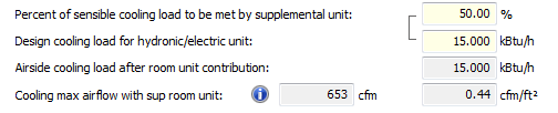
Percent of sensible cooling load to be met by supplemental unit
[ ] % {Disabled when ‘DOAS ventilation contribution…’ line above is active, else enable only if there is chilled ceiling or similar radiant/convective cooling panel device present in the “Chilled ceilings” list a Room component on the layer (this can be either the ‘Principal Room’ as the main occupied space or a ‘Non-principal Room’ component, as in when the latter is used to model a thermally stratified zone immediately above the occupied zone), and Autosize checkbox in the cooling device controller must be checked.
This percentage setting and the room unit load derived from it are linked and both editable:
Default is 100% when a room unit is present on the current layer and the ‘Autosize’ checkbox in its controller is checked. Editing this value apportions the load between the room unit and airside cooling, as in the example above. A revised Cooling max airflow value is then calculated based upon portion of the load remaining to be addressed by the airside HVAC.
The bi-directional editing of linked values for “Percent of … load to be met by supplemental unit” and the “Design … load for hydronic/electric unit” is not, however, allowed in the case of a DOAS wherein the % input value is irrelevant and disabled.
The presence of the “Rad/conv cool device/panel” link will be used to enable additional functionality in later ISM phases, but has not been implemented in phase 1 for VE2016.
Design cooling load for hydronic/electric unit
[ ] kW {derived: add DOAS contribution…(+/-) value above to Cooling design load with oversize/adjustment OR multiply Cooling design load with oversize/adjustment by the Percent… immediately above; whichever is active. When FCU Cooling airflow CAV/2sp/VAV or Act bm/IU Primary air CAV/VAV cool or PTAC/PTHP cool airflow CAV/2sp/VAV link is present, revise text label to “Cooling load for terminal unit”. If derived value is negative, ignore this and display zero. Test for correct derivation of DOAS vent load using system AHU/vent SAT (see under DOAS contribution, above), whereas FCU and Active beam airflow calcs should use zone SAT.
Airside cooling load after room unit contribution
[ ] kW {active only when Percent heating load… above is active; derive by subtracting value immediately above from the Cooling design load with oversize/adjustment to get the remaining load to be addressed by the airside
Cooling max airflow w/sup room unit
[ ] l/s [ ] l/s.m2 {When FCU Cooling airflow CAV/2sp/VAV or Act bm/IU Primary air CAV/VAV cool or PTAC/PTHP cool airflow CAV/2sp/VAV link is present, revise text label to “Cooling max airflow for terminal unit”, and derive the airflow from “Cooling load for terminal unit” above and the Cooling design supply air delta-T: in Cooling loads… section of this tab. When Percent cooling load… above is active; derived from Airside cooling load after room unit… above and Cooling design supply air delta-T: in Cooling loads… section of this tab.
Cooling max airflow w/sup room unit (alternately labelled “Cooling load for terminal unit”) as input to derivation of “Cooling maximum [primary] airflow” is defined as:
Cooling design maximum airflow – (Room Unit or DOAS contribution)
where the bit in parentheses is A and/or B, below, whichever is relevant:
A) Cooling max airflow w/sup room unit is the Cooling airflow requirement that results after accounting for room unit contribution to space conditioning.
B) When FCU, Act bm/IU, or PTAC/PTHP link is present, causing the text label to be revised to “Cooling max airflow for terminal unit”, is the Cooling airflow requirement that results after accounting for DOAS ventilation contribution to zone cooling load.
When FCU Cooling airflow CAV/2sp/VAV or Act bm/IU Primary air CAV/VAV cool or PTAC/PTHP cool airflow CAV/2sp/VAV link is present, derive “Cooling max airflow for terminal unit”, as:
Cooling design maximum airflow – (DOAS ventilation contribution to cooling load [kW] converted to Cooling volume airflow rate)
The kW value for DOAS ventilation contribution to cooling load is firstly derived from DOAS ventilation air tempering max SAT and max (Ventilation req., Minimum primary airflow)
where:
Ventilation req. = “Zone ventilation max/total req” l/s (cfm) column
Minimum primary airflow includes Makeup air req. (Exhaust airflow – Transfer airflow)
The kW value for DOAS ventilation contribution to cooling load must then be converted to a space cooling volume flow rate using the same equation and delta-T as used above to calculate Cooling design maximum airflow, as this will be a reduction/increase in Cooling design maximum airflow resulting from the addition/subtraction of load that the Cooling design maximum airflow must address. In effect, the code must repeat the calculation of Cooling design maximum airflow, but with the load reduced by the DOAS contribution, which will nearly always be at a different SAT than is used in the terminal units.
See section Active beam & induction units in Cooling, Heating, and DOAS maximum primary airflow: Rules and Derivations supplement regarding how DOAS ventilation contribution to cooling load (sensible load) is handled in the case of active beams. This section also describes how, for active beams, zone latent loads are addressed by the DOAS airflow (not the zone recirculated airflow), and how this is ensured when the box is checked for Force cooling design airflow to be sufficient to maintain zone RH setpoint.
Else, “Cooling max airflow w/sup room unit” is derived as:
Cooling design maximum airflow – (Airside sensible cooling load after room unit contribution converted to l/s Cooling Airflow)
The kW load value for Airside sensible cooling load after room unit contribution is converted to volume flow rate using the same equation and delta-T as used above to calculate Cooling design maximum airflow, as this will be a reduction/increase in Cooling design maximum airflow resulting from the addition/subtraction of load that the Cooling design maximum airflow must address. Room units provide only sensible cooling.
IF no room unit and none of the noted terminal unit cooling links are present, Cooling max airflow w/sup room unit = Cooling design maximum airflow, and this is used as input to derivation of Cooling maximum [primary] airflow.
Heating loads for zone-level terminal units or room units
DOAS ventilation contribution to zone heating load (+/-)
[ ] kW
Enabled when “DOAS vent airflow,” “DOAS vent airflow CAV/DCV,” or “Act bm/IU Primary air CAV/VAV heat ” parameter link is present, unless the box is checked for Ventilation or make-up for EA contributes to FCU or PTAC design flow rate on the Zone Airflows, Turndown, & Engineering Checks tab.
When ventilation is provided in the form of transfer air drawn into zone by EA function (i.e., Transfer at max EA and min primary airflow is non-zero value), which will be at RA temperature, need also to enable this parameter and revise the label to read “Transfer air contribution to zone heating load (+/-)” and delta-T used in calc needs to be based upon the zone heating setpoint and control throttling range during occupied hours:
a) IF either the “DOAS vent airflow” or “DOAS vent airflow CAV/DCV” parameter link is present, enable this derivation for the zone.
b) IF the zone value for Transfer at max EA and min primary airflow > 0, then use this transfer airflow value and a 1 ° F delta-T to determine contribution and revise text label to “Transfer air contribution to zone heating load (+/-)”.
o The very small, fixed 1 ° F delta-T is based on the assumption that, at the design condition, the target temperature for a zone conditioned only by or mainly by transfer air will be Occupied hours heating setpoint +/- Throttling Range (-2 ° F for heating in ISM phase 1), and the average RA used for transfer will be at Occupied hours heating setpoint +/- one-half the Throttling Range.
c) IF the box is checked for Ventilation or make-up for EA contributes to FCU or PTAC design flow rate on the Zone Airflows, Turndown, & Engineering Checks tab, override (a) and disable the parameter again for that particular zone.
Except when this calc is used for determining Transfer Air contribution to zone load, the displayed value is derived from overall zone ventilation airflow ( “Zone ventilation max/total req” l/s (cfm) column ), the delta-T between the Occ Hours Heating Temperature setpoint (Zone Temp… tab), and the system SAT. The DOAS contribution always uses the system-level SAT, not the zone-level SAT setting. There are, however, two relevant possible DOAS heating (or at least non-cooling) SAT values the Primary air section on the System Parameters tab:
For derivation of DOAS ventilation contribution to zone heating load (+/-), use “System min SAT for space cooling & vent tempering” OR “DOAS ventilation air tempering max SAT” OR “Heating mode max SAT” on System Parameters tab, depending on which of these three parameters is enabled (per links required for each of them). If more than one of these are enabled, use the MAX value from among them, as the warmest heating mode SAT enabled will be the relevant one.
-
The Heating mode max SAT parameter as input to this calc is active only when either “
Heating coil – min SAT w reset” or “
Heating coil – full heating LAT band” links link is present.
-
When the Heating mode max SAT parameter is
not active, the resulting value should typically
add to the zone heating load, as ventilation air will normally be supplied at a temperature
below the room air temp setpoint. See LD spreadsheet Sys 9 tab column CH for example calc.
-
When the Heating mode max SAT parameter
is active, the resulting value should typically
reduce zone heating load, as ventilation air will in this case typically be supplied warmer than the room air temp setpoint. Display value in (parentheses) when negative.
-
When the box is checked for “Ventilation or make-up for EA contributes to FCU or PTAC design flow rate” on the Zone Airflows, Turndown, & Engineering Checks tab, the separately controlled OA airflow will pass through the terminal unit coils without operation of the terminal unit fan. The OA airflow will therefore be deducted from the calculated recirculation airflow on that tab, and thus should not contribute to the zone heating load via this parameter. While the ventilation air will still contribute to the zone-level coil load, that load is a matter for the system-level sizing of the coil, and not a factor in the airflow sizing.
-
When the space is ventilated and thus also at least partly conditioned by transfer air, the EA fan drawing transfer air into the zone will have a role very similar to a DOAS providing tempered air, in that remaining load will normally be served by room units.
-
The word “zone” has been added to the label for this parameter to make it clear that this influences the load in the space, rather than the load on the coil, which may also be affected, but is not relevant here.
-
This is a zone-level parameter that must be enabled separately for each zone (just because the system is 100% OA at the AHU doesn't mean that the primary air provided to the zones won't be the source of space conditioning in some or even all zones on the system)
-
These links will be included in new PTAC and PTHP systems using DOAS, and therefore will not be limited to pre-ISM “Type” 09 systems.}
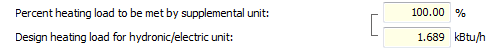
Percent heating load to be met by supplemental unit
[ ] % {Disable when ‘DOAS ventilation contribution…’ line above is active, else enabled only if there is radiator, similar convective heating device, or radiant heating panel present in the “Radiators” list a Room component on the layer (this can be either the ‘Principal Room’ as the main occupied space or a ‘Non-principal Room’ component, as in when the latter is used to model a thermally stratified zone immediately above the occupied zone), and Autosize checkbox in the cooling device controller must be checked.
This percentage setting and the room unit load derived from it are linked and both editable:
Default is 100% when a room unit is present on the current layer and the ‘Autosize’ checkbox in its controller is checked. Editing this value apportions the load between the room unit and airside cooling, as in the example above. A revised Cooling max airflow value is then calculated based upon portion of the load remaining to be addressed by the airside HVAC.
The bi-directional editing of linked values for “Percent of … load to be met by supplemental unit” and the “Design … load for hydronic/electric unit” is not, however, allowed in the case of a DOAS wherein the % input value is irrelevant and disabled.
The presence of the “Rad/conv heat device/panel” link will be used to enable additional functionality in later ISM phases, but has not been implemented in phase 1 for VE2016.
Design heating load for hydronic/electric unit
[ ] kW {derived: add DOAS contribution…value above to Heating design load with oversize/adjustment OR multiply Heating design load with oversize/adjustment by the Percent… immediately above; whichever is active. When FCU Heating airflow CAV/2sp/VAV or Act bm/IU Primary air CAV/VAV heat or PTAC/PTHP heat airflow CAV/2sp/VAV link is present, revise text label to “Heating load for terminal unit”. In all cases, if the derived value is negative, set it to zero (ignore negative derived values). Test for correct derivation of DOAS vent load using system AHU vent SAT, whereas FCU airflow calcs should use ZONE SAT. }
Airside heating load after room unit contribution
[ ] kW {active only when Percent heating load… above is active; derive by subtracting value immediately above from the Heating design load with oversize/adjustment to get the remaining load to be addressed by the airside}
Heating max airflow w/sup room unit
[ ] l/s [ ] l/s.m2) { When FCU Heating airflow CAV/2sp/VAV or Act bm/IU Primary air CAV/VAV heat or PTAC/PTHP heat airflow CAV/2sp/VAV or FPB Secondary airflow CAV/2sp/VAV (applies only to heating) link is present, the label is revised to “Heating max airflow for terminal unit”, and the airflow is derived from “Heating load for terminal unit” above and the Heating design supply air delta-T: in Heating loads… section of this tab. When Percent heating load… above is active; derived from Airside heating load after room unit… above and Heating design supply air delta-T: in Heating loads… section of this tab.
Heating max airflow w/sup room unit (alternately labelled “Heating load for terminal unit”) as input to derivation of “Heating maximum [primary] airflow” is defined as:
Heating design maximum airflow – (Room Unit or DOAS contribution)
where the bit in parentheses is A and/or B, below, whichever is relevant:
A) Heating max airflow w/sup room unit is the Heating airflow requirement that results after accounting for room unit contribution to space conditioning.
B) When FCU, Act bm/IU, or PTAC/PTHP link is present, causing the text label to be revised to “Heating max airflow for terminal unit”, this is the Heating airflow requirement that results after accounting for DOAS ventilation contribution to zone cooling load.
When FCU Heating airflow CAV/2sp/VAV or Act bm/IU Primary air CAV/VAV heat or PTAC/PTHP heat airflow CAV/2sp/VAV link is present, “Heating max airflow for terminal unit” is derived as:
Heating design maximum airflow – (kW DOAS ventilation contribution to cooling load converted to l/s Heating Airflow)
The kW value for DOAS ventilation contribution to heating load is firstly derived from DOAS ventilation air tempering min SAT and max (Ventilation req., Minimum primary airflow)
Where:
Ventilation req. = “Zone ventilation max/total req” l/s (cfm) column
Minimum primary airflow includes Makeup air req. (Exhaust airflow – Transfer airflow)
The kW value for DOAS ventilation contribution to heating load is then converted to a space cooling volume flow rate using the same equation and delta-T as used above to calculate Heating design maximum airflow, as this will be a reduction/increase in Heating design maximum airflow resulting from the addition/subtraction of load that the Heating design maximum airflow must address. In effect, the calculation of Heating design maximum airflow is repeated, but with the load reduced by the DOAS contribution, which will nearly always be at a different SAT than is used in the terminal units.
Else, “Heating max airflow w/sup room unit” is derived as:
Heating design maximum airflow – (Airside sensible heating load after room unit contribution converted to l/s Heating Airflow)
The kW load value for Airside sensible heating load after room unit contribution is converted to volume flow rate using the same equation and delta-T as used above to calculate Heating design maximum airflow, as this will be a reduction/increase in Heating design maximum airflow resulting from the addition/subtraction of load that the Heating design maximum airflow must address.
IF no room unit and none of the noted terminal unit heating links are present, Heating max airflow w/sup room unit = Heating design maximum airflow, and this is used as input to derivation of Heating maximum [primary] airflow.
Room unit autosizing
a) For cooling/heating hydronic/electric room units (excluding Direct-acting heater/coolers), the ‘Autosize’ checkbox in the room unit controller dialog takes the place or a system parameter link and must be ticked to establish the link to the System Parameters interface.
b) The presence of a cooling/heating hydronic/electric room unit (excluding Direct-acting heater/coolers) with the ‘Autosize’ checkbox ticked causes the respective section of the System Parameters interface to be enabled.
c) The “DOAS ventilation contribution to cooling load (+/-)” line, and same for heating, is enabled according to the rules described in that section above. The DOAS contribution to the load (+/-) feeds into the derived “Design cooling load for hydronic/electric unit”, as also described in that section above (same for heating unit).
d) If not a DOAS, the “Percent of sensible cooling load to be met by supplemental unit” will thus be enabled in lieu of the DOAS input line (same for heating).
e) Entering any non-zero value in the “Percent of sensible cooling load to be met by supplemental unit”, causes the derived value for “Design cooling load for hydronic/electric unit” or to be updated (same for heating unit).
f) In all cases, so long as the ‘Autosize’ checkbox is ticked in the room unit controller dialog, the derived value for “Design cooling load for hydronic/electric unit” is copied to the Design cooling load input field in the respective room unit controller dialog when the user clicks ‘Assign’ (same for heating).
g) Upon upgrade of a legacy system (first time only), if ‘Autosize’ is checked in room unit controller dialog, the existing Design load value from the room unit is copied to the Design cooling/heating load for hydronic/electric unit in the System Parameters UI and % cooling/heating load immediately above that is derived using this value.