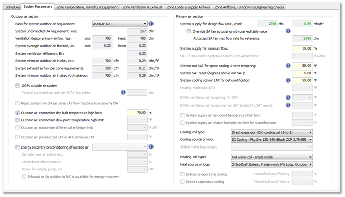
Outdoor air section
Basis for system outside air requirement
The ‘Basis for system minimum OA requirement’ is most often matched to that of all zones on the system (e.g., ASHRAE 62.1 in all cases); however, users are permitted to combine methods at zone and system levels, as is required in certain healthcare facilities and laboratories. This setting is disabled for single-zone systems.
Options:
· ASHRAE 62.1
· Sum of zone OA requirements
The default option is set in the ApacheHVAC Preferences dialog.
System uncorrected OA req. (Vou)
This is the system uncorrected outdoor air intake for ASHRAE 62.1 ventilation (for all zone layers using ASHRAE 62.1 as the basis for zone ventilation), accounting for diversity in zone occupancy, but prior to the influence of the system ventilation efficiency (equivalent to the ventilation efficiency for the critical zone). This is disabled for single-zone systems and when ‘Basis for system outside air requirement’ is other than ASHRAE 62.1.
Ventilation design primary airflow (Vps)
This is the ASHRAE 62.1 system primary airflow rate at the ventilation design condition analyzed (the sum of Vpz for all zone layers using ASHRAE 62.1 as the basis for zone ventilation). Because Vpz will differ for Cooling vs. Heating modes, Vps is calculated and displayed separately for each mode. This is disabled for single-zone systems and when ‘Basis for system outside air requirement’ is other than ASHRAE 62.1.
System average outdoor air fraction (Xs)
This is the ASHRAE 62.1 fraction of outdoor air, based on the uncorrected outdoor air intake (Vou) as a fraction of the System primary airflow (Vps) for the system air handler operating at the ventilation design condition analyzed. Because Vpz will differ for Cooling vs. Heating modes, and therefore Vps is calculated separately for each mode, Xs is also calculated and displayed separately for each mode. This is disabled for single-zone systems and when ‘Basis for system outside air requirement’ is other than ASHRAE 62.1.
System ventilation efficiency (Ev)
This is the ASHRAE 62.1 system ventilation efficiency, which is equivalent to the ventilation efficiency for the critical zone or zones on the system (the zone or zones having the lowest Evz value). This is disabled for single-zone systems and when ‘Basis for system outside air requirement’ is other than ASHRAE 62.1.
System minimum outdoor intake (Vot)
This is system minimum outdoor ventilation requirement before considering the possibility of a greater requirement for outside air to make up for total system exhaust airflow.
When ‘Basis for system outside air requirement’ is set to ‘Sum of zone OA requirement, this value is just that: the sum of the zone outside air requirements. Note that make-up air requirements will already be included in zone outside air requirements is the make-up air supplies to the zone is primary air rather than transfer air.
When ‘Basis for system outside air requirement’ is set to ASHRAE 62.1, this is System uncorrected OA req. (Vou) divided by System ventilation efficiency (Ev).
· If ‘100% outside air system’ box is checked on ‘System Parameters’ tab, System minimum outdoor intake (Vot) is equal to the sum of Voz for all zones (all multiplex layers) on the system.
· If ‘Configuration’ at the top level of ‘System Parameters’ dialog is ‘Single-zone systems’ or ‘Packaged terminal units’, System minimum outdoor intake (Vot) = Zone outdoor airflow ( Voz ). In this case, the System Parameters tab is a zone-level tab, as there is one zone per system, and thus the values on this tab are specific to each zone (and multiplex layer).
System exhaust airflow per zone requirements
This is the total combined exhaust airflow for all zones on the system, and therefore the total requirement for make-up air, regardless of whether this is primary air or transfer air at the zone level. This parameters will be a Zone value for the current display layer when Configuration = Single-zone systems or Packaged terminal units (system = 1 zone).
System minimum outdoor intake (Vot / make-up)
This is the greater of the values for ‘System minimum outdoor intake’ and ‘System exhaust airflow per zone requirements’. It is the minimum value that will be used in the outside air dampers with either the ‘Outside air min + econ’ or ‘Outside air fixed min’ damper component parameter links. This does not apply to dampers with “…variable min” or “…no min” links.
þ 100% outside air system
This checkbox sets behavior for a range of parameters relevant to 100% outside air systems vs. those with system system-level recirculation of return air.
When any of the following four links are present—indicating the presence of an OA economizer damper set—this checkbox is unchecked: “ Outside air min + econ ”; “ Outside air no min econ ”; “ Outside air variable min ”; “ Outside air fixed min ”; or “ Return-air damper ”.
When none of the five links above is present—indicating a system with no damper for mixing outside air with recirculated air, and thus a 100% OA system—this box is automatically checked by default. It can be manually unchecked if, for example, a recirculating damper is added, but there is a desire to avoid using any of the links provided.
When “100% outside air system” is manually checked—overriding an automated default unchecked state that resulted from the presence of the links noted above—the value for “System minimum outdoor air intake, Vot/make-up” is set to the greater of the values for ‘System minimum outdoor air intake (Vot)’, ‘System exhaust airflow per zone requirements,’ and ‘System supply fan design flow rate, (Vpsd)’. This does not apply, however, when '100% outside air system' is automatically checked for DOAS systems that contain no economizer damper links.
Total of zone minimum primary (OA) flow rates:
The value displayed is the sum of ‘DOAS max primary airflow to zone’ for all zones on the system, as is displayed for each zone on the Zone Airflows, Turndown, & Engineering Checks tab. If this sum is not greater-than-or-equal-to ‘System exhaust airflow per zone requirements’ (the total of all zone-level exhaust air requirements on the system), this parameter is flagged as an error condition that must be addressed prior to running a loads analysis or simulation.
To ensure adequate make-up air, the “Total of zone minimum primary (OA) flow rates” in any DOAS must be greater than or equal to the total “System exhaust airflow per zone requirements.” If this is flagged as insufficient (Error condition with red value for "Total of zone minimum primary (OA) flow rates"), ventilation rates for one or more zones must be increased until it is sufficient. For a DOAS with variable primary airflow rates, as with Demand-Controlled Ventilation (DCV), the minimum flow rates to one or more zones must be increased until the total minimum make-up airflow on the system is sufficient.
This parameter is enabled only when the 100% outside air system checkbox is checked and the DOAS max primary airflow to zone parameter on the Zone Airflows, Turndown, & Engineering Checks tab is enabled (i.e., when one of the four DOAS or Active Beam links is present in at least one zone on the system).
þ Reset system min OA per zone VAV flow fractions to ensure %OA
The checkbox is enabled and checked by default whenever either the OA min reset - zn VAV flow % link or OA min reset - Occupied zn VAV% is present. The box can be manually un-checked to disable this control if needed.
If OA min reset - Occupied zn VAV% link is present AND ‘Min when unoccupied’ (DCV reduction to VozA) is checked on the Zone Ventilation & Exhaust tab for at least one zone, this checkbox is enabled and forced-checked.
The checkbox is disabled if ‘Configuration’ is single-zone systems.
þ Outdoor air economizer dry-bulb temperature high limit:
{Requires “ OA econ target & DBT limit ” link, else grey out. The link enables the checkbox, and checking the box enables the parameter, with default of 70 F, makes it editable, and causes it to be applied to the controller, along with setting of the time switch profile, when the user clicks Assign. The time switch profile in the controller should be set to ON continuously when the option is engaged (box checked) and set to OFF continuously when the option is disengaged (box unchecked). Ticked by default when this link is present. On upgrade from legacy system, pick up value from cell E24 on Sys 5,7 tab (regardless of sys type).}
þ Outdoor air economizer dew-point temperature high limit)
{Requires “ OA econ DPT limit ” link, else grey out. T he link enables the checkbox, and checking the box enables the parameter, with default of 56 F, makes it editable, and causes it to be applied to the controller On/Off Setpoint when the user clicks Assign (or upon auto-assign) . Leave time switch profile in the “OA econ DPT limit” controller set to ON continuously (as it is when loaded as part of HVAC library prototype system), do not change the time switch profile when the box is unchecked.}
þ Outdoor air economizer differential enthalpy limit
{req. “OA econ diff enthalpy” link, else grey out}
(Permits economizer operation when OA enthalpy is less than RA enthalpy by at least this value. Enter positive number.}
þ Outdoor air pre-heat coil LAT or AHU minimum EAT
{greyed out if “Pre-heat coil–AHU min EAT” link not present; checked box causes the time switch profile in the linked controller to be changed upon Assign to ON continuously ; unchecked box causes the time switch profile in the linked controller to be changed upon Assign to OFF continuously .}
þ Energy recovery preconditioning of outside air
Options:
· Bypass for system sizing (default)
· ON for system sizing
Enabling energy recovery for preconditioning of outside air in any prototype system with energy recovery will also enable an additional fan component to account for the additional pressure drop and thus added fan energy required at the system supply fan when the intake air is flowing through the ER device (i.e., whenever the ER is not bypassed). The fan and motor efficiency values in this additional fan component on the ER path should be set to match those in the system Supply Fan component. The default 1” static pressure value should be adjusted to represent just the added pressure associated with the particular ER device being modeled.
‘Energy recovery preconditioning of outside air’ and the 3 inputs below are greyed out if “Energy recovery HX/wheel” link is not present.
Sensible heat effectiveness: [ ] %
This is the ‘Sensible heat effectiveness (%)’ input for the air-to-air heat/enthalpy exchanger component with ‘Energy recovery HX/wheel’ link.
Latent heat effectiveness: [ ] %
This is the ‘Latent heat effectiveness (%)’ input for the air-to-air heat/enthalpy exchanger component with ‘Energy recovery HX/wheel’ link.
Power for wheel, pump, etc.: [ ] kW
This is the ‘Motor or pump power (kW)’ input for the air-to-air heat/enthalpy exchanger component with ‘Energy recovery HX/wheel’ link.
þ Exhaust air (in addition to RA) is available for energy recovery
When the “EA% available to ER” link is present, this checkbox determines whether separately exhausted air (i.e., via separate exhaust fan or fans) is added to the general exhaust from the system air handler upstream of the airside energy recovery device or is otherwise separately discharged and not available for energy recovery.
Primary air section
System supply fan design flow rate (Vpsd)
This editable autosized value is the design flow rate used in the Supply Air (SA) Fan component dialog. Prior to system-level autosizing, it is derived as the sum of the maximum primary airflow values in the System Parameters dialog for all zones on the system. When autosized, the autosized l/s (cfm) value for the SA Fan Component (with system parameter link “Supply fan”) is displayed in the first of the two fields, and this is divided by total floor area for all zones served by the associated HVAC network to obtain the l/s-m2 (cfm/ft2) value for the second field. If manually edited, the edited value is retained until the next autosizing update. Overwriting the edited value by the autosizing operation can be prevented by the checkbox below.
þ Override SA fan autosizing with user-edited value
When ticked, this maintains the initially derived or manually set value for ‘System supply fan design flow rate (Vpsd)’—i.e., that value will not be overwritten by autosizing. Checking this box also disables the derivation of the System supply fan design flow rate as the sum of the maximum primary airflows for all zones on the system to avoid a circular reference.
This differs from unchecking the ‘Autosize’ box in the SA Fan component prevents, which prevents overwriting of the Design flow rate’ value just within that component dialog.
Note: When override SA fan autosizing is checked, the editable System supply fan design flow rate above this will no longer be revised by autosizing. In all cases, ASHRAE 62.1 calculations will use the value here to represent the highest expected system primary airflow (Vps) at the design condition, which is the basis for determining the average outdoor air fraction (Xs).
Autosized SA fan max flow rate for reference
This value is for reference only and remains uneditable and autosized, regardless of the checkbox for ‘Override SA fan autosizing with user-edited value’ or edits to ‘System supply fan design flow rate (Vpsd)’.
System supply fan minimum flow
This is the minimum flow fraction (% of maximum design flow) permitted for the system when the system fan is engaged for intermittent off-hours operation—e.g., assuming the SA fan has a minimum feasible flow rate when just one or a few zones on the system requires heating via system airflow during unoccupied hours. This requires “Min fan airflow” link and is disabled for single-zone systems.
90.1 PRM Baseline System Pressure Drop Adjustment
This is enabled only for 90.1 PRM Baseline systems. It is editable here and via the PRM Navigator.
System min SAT for space cooling & vent tempering
‘System min SAT’ is the cooling coil minimum leaving air temperature (LAT) for space cooling and ventilation air tempering, as well as the system AHU heating coil minimum LAT.
If ‘System cooling coil min LAT for dehumidification’ is set less than ‘System min SAT’, demand for dehumidification will be permitted to drive the cooling coil LAT below min SAT, forcing reheat; however, demand for space cooling will not be permitted to do so.
This parameter is enabled if any one of the following parameter links is present:
· Cooling coil – AHU cool LAT
· Heating coil – AHU min SAT
· Heating coil – min SAT w reset
· Cooling coil – full cooling LAT band
· Cooling coil – full h/c LAT band
· Heating coil – full h/c LAT band
· Cooling coil – AHU dehum LAT
· Cool coil – AHU extend dehum LAT
· Cooling coil – AHU supply air DPT
· ER target – PSZ heat-cool
· ER bypass temp target – PSZ
· OA econ target & DBT limit
System SAT reset (above min SAT)
This is the maximum delta-T for system supply air temperature reset relative to the value for ‘System min SAT for space cooling & vent tempering’. Note that this is the maximum reset value for the air leaving the air-handling unit; however, the cooling coil LAT may be lower than the min SAT for dehumidification, as permitted by the ‘System cooling coil min LAT for dehumidification’ input below.
This parameter is enabled if any one of the following parameter links is present (differences in values as noted):
· Cooling coil – AHU cool LAT (Sys min SAT for space cooling... + SAT reset degrees above sys min SAT)
· Cooling coil – AHU dehum LAT (Sys min SAT for space cooling... + SAT reset degrees above sys min SAT)
· Cool coil – AHU extend dehum LAT (Sys min SAT space cooling..+ (SAT reset deg above sys min SAT +5 °F)
· Cooling coil – AHU dehum LAT (Sys min SAT for space cooling... + SAT reset degrees above sys min SAT)
· Cooling coil – DOAS tempering (DOAS ventilation air tempering max SAT + SAT reset degrees above min SAT)
· Cooling coil – DOAS dehum (DOAS ventilation air tempering max SAT + SAT reset degrees above min SAT)
· Energy recovery bypass (Sys min SAT for space cooling... + SAT reset degrees above sys min SAT)
· Energy recovery HX/wheel (Sys min SAT for space cooling... + SAT reset degrees above sys min SAT)
System cooling coil min LAT for dehumidification
‘System cooling coil min LAT for dehumidification’ is a secondary LAT setpoint for the system cooling coil that applies only in the case of system or zone demand for dehumidification. If it is set to a temperature less than ‘System min SAT’, demand for dehumidification will be permitted to drive the cooling coil LAT below the min SAT, forcing reheat; however, demand for space cooling will not be permitted to do so.
Standard default = 50.0 °F; default = 60 °F if “Heating coil – DOAS tempering” link is present.
This parameter is enabled if any of the following links is present:
· Cooling coil – AHU dehum LAT
· Cool coil – AHU extend dehum LAT (linked value = System cooling coil min LAT for dehumidification -5 ° F)
· Cooling coil – AHU supply air DPT
· Cooling coil – DOAS dehum
· Cooling coil – full dehum LAT band
· Cooling coil – full h/c/dehum LAT
Heating mode max SAT
Enabled for “Heating coil – min SAT w reset” or “Heating coil – full heating LAT band” links.
DOAS ventilation air tempering min SAT
Enabled if “Heating coil – DOAS tempering” link is present; Default = 60 F.
Used in calculation of “DOAS ventilation contribution to cooling load (+/-)”, except with Active Beam link, which can use either “System min SAT for space cooling & vent tempering,” or this parameter as the supply temperature, whichever is enabled by controller links.
DOAS ventilation air tempering max SAT (subject to SAT reset)
Enabled if “Cooling coil – DOAS tempering” link is present; Default = 60 F.
This is used in calculation of “DOAS ventilation contribution to heating load (+/-)”, except with Active Beam link, which can use either this parameter OR “System min SAT for space cooling & vent tempering,” whichever is enabled by controller links.
If the system is a DOAS (per ventilation controller links), the “DOAS ventilation air tempering min SAT” and “DOAS ventilation air tempering max SAT” will be enabled and take the place of the dual functions of the “System min SAT for space cooling & vent tempering” parameter, as well as the “Heating mode max SAT” above. This provide a simple pair of min and max values for tempered ventilation air leaving the DOAS AHU with default values typical of this system type.
The DOAS AHU heating coil should still, however, be located downstream of the cooling coil to provide reheat (or a heat pipe or heat recovery device should be provided for this purpose) whenever “System cooling coil min LAT for dehumidification” is set to a value less than the “DOAS ventilation air tempering min SAT”, as the lower minimum will permit demand for dehumidification to drive the cooling coil LAT to a temperature below the min SAT for tempered ventilation air.
þ System supply air dew-point temperature high limit
This allow entering and enforcing a value for the maximum dew-point temperature leaving the system air handler (or wherever the sensor is placed) with the appropriate cooling coil controller link present. Enabled if either Cooling coil – AHU supply air DPT (Independent Controller with Sensor) link or Cooling coil – coil leaving DPT (Independent Time Switch) link is present. Both of these links use the value for this parameter. Checked by default when enabled.
þ System supply air relative humidity low limit for humidification
This allow entering and enforcing a value for the minimum system supply air relative humidity leaving the system air handler (or wherever the sensor is placed) with the appropriately linked spray chamber or seam humidifier controller. Enabled if either Evap/spray humid per SA RH or Steam humid per SA RH link present; un-checked by default.
Cooling coil type
Sets this parameter in coil dialog. Enabled if “AHU cooling coil” link is present. Options are the same as those in the coil dialog.
Cooling source or loop
Sets this parameter in coil dialog. Enabled if “AHU cooling coil” link is present. Options are the same as in options in the coil dialog.
Chilled water loop circuit
Sets this parameter in coil dialog. Enabled if “AHU cooling coil” link is present. Options are the same as in options in the coil dialog.
Heating coil type
Sets this parameter in coil dialog. Enabled if “AHU heating coil” link is present. Options are the same as in options in the coil dialog.
Heat source or loop
Sets this parameter in coil dialog. Enabled if “AHU heating coil” link is present. Options are the same as in options in the coil dialog.
þ Indirect evaporative cooling
Checking this box changes the linked controller time switch profile from “ OFF cont. ” to “ ON cont. ”; enabled if “Indirect-evap cooling” link is present; checked by default when link is present.
Humidification Efficiency
Enable, independent of Indirect evaporative cooling checkbox above being enabled, as Spray Efficiency input to Spray Chamber when “ Indirect-evap/spray ” component link is present; default = 85%.
þ Direct evaporative cooling
Checking this box changes controller time switch profile from “ OFF cont. ” to “ ON cont. ”; enabled if “Direct-evap cooling” link is present; checked by default when link is present.
Humidification Efficiency
Enabled as Spray Efficiency input to Spray Chamber component when “ Direct-evap/spray ” or Steam humidifier component link is present, default = 85%. >: Insert description text here... And don't forget to add keyword for this topic