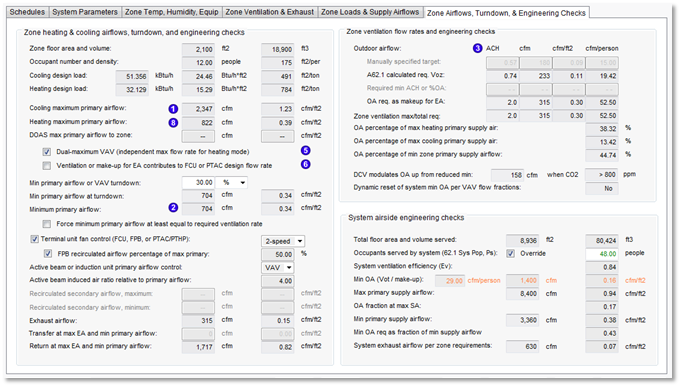
Zone Airflows, Turndown, & Engineering Checks tab
Zone heating & cooling airflows, turndown, and engineering checks
Zone floor area and volume
[ ] m2 [ ] m3 {from Space Data for Principal room on multiplex layer}
Occupant number and density
[ ] people [ ] m2/per {peak Space Data value with diversity factor applied)
Cooling design load
[ ] kW [ ] kW/m2 [ ] m2/kW {IP unit is ft2/ton, 1 ton = 12,000 Btu/h }
Heating design load
[ ] kW [ ] kW/m2 [ ] m2/kW {IP unit is ft2/ton, 1 ton = 12,000 Btu/h }
Cooling maximum primary airflow
[ ] l/s [ ] l/s.m2 When links for DOAS vent airflow, DOAS vent airflow CAV/DCV, PTAC/PTHP cool airflow CAV/2sp/VAV, or UCS Cooling airflow are present, revise label text for this parameter to omit the word “primary”. Values derived as indicated in info button note, with specialized calculations in the case of active beams and induction units in which the required airflow calculated on the previous tab according to the load is divided by the induction ratio:
The load added or removed by the primary air at system SAT must be calculated to determine the total volume of air needed at the zone terminal unit supply temperature (zone coil LAT) to meet the load, and this volume must be divided by the induction ratio to obtain the primary airflow. This is consistent with the info button note below.
Cooling maximum primary airflow is the greater of the following zone airflow requirements:
· Cooling max airflow w/sup room unit (Cooling design maximum airflow after room unit deductions)
· Primary air-change requirement, per settings in the Zone Ventilation & Exhaust tab
· Ventilation and makeup air requirements, as determined by options below and settings in Zone Loads & Supply Airflows and Zone Ventilation & Exhaust tabs.
This is the primary airflow that will be used for the max value in VAV and 2-speed Cooling airflow controls. When Configuration at the top of the System Parameters dialog is set to CAV, both Cooling and Heating controls will use the greater of the Cooling/Heating maximum primary airflow values. Setting Configuration to VAV allows for a minimum primary airflow and independent Cooling &Heating max airflow values.
In PTACs, PTHPs, and DOAS systems where Fan-Coil Units or similar recirculate zone air for space conditioning, the word “primary” is omitted, and this parameter is simply “Cooling maximum airflow.” For all DOAS systems, the “DOAS max primary airflow to zone” parameter immediately below is the relevant primary airflow.
Active beams and induction units are a special case in which the required airflow calculated according to the load on the previous tab is divided by the induction ratio. The volume of air induced through the coils will be that calculated as required to meet the load, including any load contributed by the primary airflow, and the primary airflow will be that required to induce this volume flow rate.
When 'Configuration' is ' CAV ' rather than ' VAV ,' the zone 'Cooling maximum primary airflow' label should read 'Constant-volume primary airflow ,' both check boxes for 'Dual-max...' and first two zone parameters for 'Min primary airflow...' should be disabled, 'Min primary airflow' should be equal to max, and 'DOAS max primary airflow to zone' should read ' DOAS CV primary airflow to zone ,' (excepting DOAS zones with DCV engaged, which must be variable primary flow).
Heating maximum primary airflow
[ ] l/s [ ] l/s.m2 { When links for DOAS vent airflow , DOAS vent airflow CAV/DCV , or PTAC/PTHP heat airflow CAV/2sp/VAV are present, dynamically revise label text for this parameter to omit the word “primary”. The presence of the FPB Secondary airflow CAV/2sp/VAV link should also cause the labeling for “Heating maximum primary airflow” to be revised to just “Heating maximum airflow” (applies only to heating airflow). Values derived as indicated in info button note, with specialized calculations in the case of active beams and induction units are a special case in which the required airflow calculated on the previous tab according to the load is divided by the induction ratio:
The load added or removed by the primary air at system SAT must be calculated to determine the total volume of air needed at the zone terminal unit supply temperature (zone coil LAT) to meet the load, and this volume must be divided by the induction ratio to obtain the primary airflow. This is consistent with the info button note below.
Heating maximum primary airflow is the greater of the following zone airflow requirements:
-
Heating max airflow w/sup room unit (Heating design maximum airflow after room unit deductions)
-
Primary air-change requirement, per settings in the Zone Ventilation & Exhaust tab
-
Ventilation and makeup air requirements, as determined by options below and settings in Zone Loads & Supply Airflows and Zone Ventilation & Exhaust tabs.
This is the primary airflow that will be used for the max value in VAV and 2-speed Heating airflow controls. When Configuration at the top of the System Parameters dialog is set to CAV, both Cooling and Heating controls will use the greater of the Cooling/Heating maximum primary airflow values. Setting Configuration to VAV allows for a minimum primary airflow and independent Cooling &Heating max airflow values (see setting for dual-maximum VAV operation).
In PTACs, PTHPs, and DOAS systems where Fan-Coil Units or similar recirculate zone air for space conditioning, the word “primary” is omitted, and this parameter is simply “Heating maximum airflow.” For all DOAS systems, the “DOAS max primary airflow to zone” parameter immediately below is the relevant primary airflow.
Active beams and induction units are a special case in which the required airflow calculated according to the load on the previous tab is divided by the induction ratio. The volume of air induced through the coils will be that calculated as required to meet the load, including any load contributed by the primary airflow, and the primary airflow will be that required to induce this volume flow rate.
When 'Configuration' is ' CAV ' rather than ' VAV ,' the zone 'Maximum primary airflow' label should read 'Constant-volume primary airflow ,' both radio buttons for 'Dual-max...' vs. 'Single max...' and all three zone parameters for 'Min primary airflow...' should be disabled, and 'DOAS max primary airflow to zone' should read ' DOAS CV primary airflow to zone .'
DOAS max primary airflow to zone
[ ] l/s [ ] l/s.m2 {enabled when any of four links below are present and set as noted:
-
For either DOAS vent airflow or DOAS vent airflow CAV/DCV link
DOAS max primary airflow to zone = max(“Max req” on Zone ventilation & Exhaust tab, Minimum primary airflow)
-
When either
Act bm/IU Primary air CAV/VAV cool or
Act bm/IU Primary air CAV/VAV heat link is present, AND neither DOAS vent… link above it present, this parameter is set to the greater of the two values for Cooling maximum airflow and Heating maximum airflow, above, with those values having been calculated according to calculation requirements for the special case of Active beams.
Dual-maximum VAV (independent max flow rate for heating mode)
When dual-maximum control is engaged, the heating mode design max airflow is set based upon zone loads on the Zone Loads & Supply Airflows tab, and will be at least equal to or greater than the flow rate determined by VAV min turndown. When the VAV control mode is single maximum (dual-maximum is not engaged), the min VAV flow rate will be forced equal to the heating mode design max airflow.
The dual-maximum checkbox here is a duplicate of the same option on the Zone Loads & Supply Airflows tab. These are two instances of the same control—directly coupled at all times; checked by default.
¨ Ventilation or make-up for EA contributes to FCU or PTAC design flow rate
This option deducts the flow rate for ventilation or make-up air (when zone exhaust is specified) from the calculated FCU or PTAC terminal unit design airflow for heating and cooling. The remainder of the design airflow is the controlled recirculation airflow rate. This should be used only when the ventilation air or make-up for exhaust supplied by the system is routed to pass through the terminal unit coils, thereby contributing to the volume of air driven through the coils by the local terminal unit fan. When both ventilation and exhaust are present, the greater of these two values will be deducted autosized recirculation flow rate. This allows for systems wherein the continuous operation of system fans for either ventilation or exhaust is used to either blow or draw air through the zone fan-coil unit (FCU) or packaged terminal air-conditioning or heat-pump unit (PTAC or PTHP), thus making the operation of a fan in the terminal unit supplemental and required only to recirculate additional room air through the coils.
Unchecked by default. This option deducts ventilation or make-up air for exhaust fans from the calculation of recirculated airflow to be driven through FCU/PTAC/PTHP coils by local terminal unit fan. The LD spreadsheet (cell P31 and Q31 on Sys 9 tab) provides an example of how this works when the box is checked. This includes both setting the recirculated flow to zero when exceeded by the ventilation or make-up for EA flow and the deduction of either ventilation or make-up for EA flow from the recirculated flow when it is larger than either of those. When not checked, avoid setting anything to zero or making any such deductions from the flow required to meet the Cooling or Heating load. Feeds into controllers with link set to one of the following:
· FCU Cooling airflow CAV/2sp/VAV
· FCU Heating airflow CAV/2sp/VAV
· PTAC/PTHP cool airflow CAV/2sp/VAV
· PTAC/PTHP heat airflow CAV/2sp/VAV
Min primary airflow or VAV turndown
[ ] [% | l/(s.m2) ▼ ] {% value used for derivation of next parameter. Enabled if system configuration is VAV or if DCV is engaged without A62.1 used as Basis for OA req., otherwise disabled.
Min primary airflow at turndown
[ ] l/s [ ] l/s.m2 {derived as follows:
When % units for ‘Min primary airflow or VAV turndown’
IF DOAS max primary airflow to zone is enabled, Min primary airflow at turndown (l/s) = DOAS max primary airflow to zone ´ %
else, Min primary airflow at turndown (l/s) = max(Cooling maximum primary airflow, Heating maximum primary airflow) ´ %
In either case, Min primary airflow at turndown (l/s.m2) = Min primary airflow at turndown (l/s) ´ Zone floor area
When l/(s.m2) units for ‘Min primary airflow or VAV turndown’
Min primary airflow at turndown (l/s) = Min primary airflow or VAV turndown (l/s.m2) ´ Zone floor area (m2)
Min primary airflow at turndown (l/s.m2) = Min primary airflow or VAV turndown (l/s.m2)
Minimum primary airflow
[ ] l/s [ ] l/s.m2
IF Configuration is CAV AND neither DOAS link (DOAS vent airflow or DOAS vent airflow CAV/DCV) is present
= MAX(Cooling maximum primary airflow, Heating maximum primary airflow);
else, IF Configuration is CAV AND either DOAS link is present
= DOAS max primary airflow to zone;
else, IF Configuration is VAV
= MAX(Min primary airflow at turndown, VozA , …
IF (DOAS link present, 0, Primary air-change requirement)
IF (Force design minimum primary airflow at least equal to required ventilation rate = true, Zone ventilation max/total req., 0),
IF ( AND(Exhaust air-change requirement is checked, Make-up air is 100% primary air = true), Exhaust air-change req., 0),
IF (Make-up air includes fixed percentage transfer air = true, Exhaust air-change req. - ( Exhaust air-change req. ´ specified percentage), 0),
IF ( AND(Exhaust air-change requirement is checked, Transfer at max EA and min primary airflow = 0 ), Exhaust airflow - Transfer at max EA and min primary airflow, 0))
VozA = (Ra x Az)/min(Ez_Cooling, Ez_Heating)
The derived value for ‘Minimum primary airflow’ is the greater of the minimum primary airflow at turndown, primary air-change requirement, ventilation requirement as described below, and make-up air for zone exhaust when make-up air is either set to 100% primary air or the zone OA requirement is forced >/= exhaust rate.
Minimum primary airflow in VAV-reheat systems with single-max VAV controls will be at least equal to the heating airflow requirement.
The ‘Force design minimum primary airflow at least equal to required ventilation rate’ option below is relevant to and checked by default for non-DOAS mixing systems, such as typical VAV. This ensures that minimum primary airflow will be no less than the ‘Max req.’ on the ‘Zone Ventilation & Exhaust’ tab. For DOAS, this option is disabled, as DOAS minimum primary flow is always constrained by the greater of minimum ventilation and primary (non-transfer) make-up air requirements.
Whenever ‘Basis for Zone outside air requirement’ is set to ‘ASHRAE 62.1’ or ‘Maximum,’ the minimum autosized value for variable-volume primary airflow will be VozA, regardless of system sub-type or any other settings. VozA is the building area component (Ra x Az)/min(Ez_Cooling, Ez_Heating) of the ASHRAE 62.1 zone ventilation requirement.
When ‘Basis for Zone outside air requirement’ is set otherwise, minimum primary airflow in non-DOAS is permitted to be modulated down to zero, per settings for dual-maximum VAV controls and turndown.
For DOAS, the minimum ventilation rate used to constrain primary airflow will normally be the ‘Max req.’ on the ‘Zone Ventilation & Exhaust’ tab. For any zone with DCV engaged, however, a lower minimum primary flow rate is permitted as follows: When ‘Basis for Zone outside air requirement’ is set to ‘ASHRAE 62.1’ or ‘Maximum,’ this will be VozA (as defined above); when ‘Basis for Zone outside air requirement’ is set otherwise, the DCV minimum will be the value for ‘Min primary airflow at turndown.’
þ Force design minimum primary airflow at least equal to required ventilation rate
Checked by default. This option forces the overall minimum primary airflow for the zone to be at least equal to the “Zone ventilation max/total req” l/s (cfm) column for the same zone. The overall minimum is normally set in relation to the overall maximum, which may, for example, be set by a primary ACH requirements in addition to/overriding a purely load-based determination of design max airflow.
Terminal unit fan control (FCU or FPB)
[ Constant | 2-speed | Variable ▼ ] {Enabled when at least one of the following links is present: FCU Cooling airflow CAV/2sp/VAV; FCU Heating airflow CAV/2sp/VAV; FPB Secondary airflow CAV/2sp/VAV; else grayed out.
· For FCU Cooling airflow CAV/2sp/VAV link, Maximum flow maps to Flow rate at Max Sensed DBT within the linked controller;
· For both FCU Heating airflow CAV/2sp/VAV and FPB Secondary airflow CAV/2sp/VAV links, Maximum flow maps to Flow rate at Min Sensed DBT within the linked controller;
· Maximum Flow is as derived for the Recirculated airflow (max) parameter below;
· Minimum Flow is derived for both FCU and FPB controller links as follows:
o “Constant” sets Minimum flow = Maximum flow;
o “2-speed” sets Minimum flow = 0.5 ´ Maximum flow and Proportional bandwidth to 0.1 deg F;
o “Variable” sets Minimum flow = 0.0 and default proportional bandwidth (2 deg F).
Legacy System upgrades (i.e., upgrade of systems associated with a loads data spreadsheet):
Terminal Unit Fan Control is set to “Constant” for upgraded legacy systems 06 and 08 and for all PRM Baseline systems 6 & 8. This is for Baseline systems in 90.1 Performance Rating Method versions 2004, 2007 and 2010. This applies to non-Baseline system types 06 and 08 only when they are upgraded legacy systems (i.e., from an existing pre-VE2016 user project).
When upgrading any legacy system of type 09, this parameter should always be set according to the value in cell X24 on the Sys 09 tab of the Loads Data spreadsheet (it will not be relevant for certain sub-types, but that won’t matter). The default in that location is 2-speed, but it’s also possible the user could have changed this to VSD (VSD = Variable in the Terminal Unit Fan Control options).
This rule for system type 09 applies to all systems that retain the 09 in the System Frame, regardless of their name in the HVAC library. In other words, this includes PRM Baseline system 11 DOAS-FCU, which uses the Sys 09 tab of the spreadsheet (they changed the numbering scheme on us), and similarly the ECB System 007-FCU, and GM Reference 03 DOAS-FCU (which never followed the original numbering scheme).
The note below cell X24 applies to system 09b DOAS CV- FCUs, which simply has proportional control disabled, and thus set to operate as CAV, as loaded from the HVAC library; however, within ISM, one need only enable the proportional control in the controller and re-Apply the link to make all three control options available.}
þ FPB recirculated airflow percentage of max primary
[ ] % {This editable input takes precedence whenever it exceeds the value required by other inputs to derivation of Recirculated secondary airflow (max). When box is checked, this input parameter thus drives the recirculated airflow derivation (excepting when require Heating maximum airflow – Minimum primary airflow results in a greater value). Enable when FPB Secondary airflow CAV/2sp/VAV link is present; Default = Unchecked. Box is checked automatically and value set to 50% when the system containing this link is an ASHRAE 90.1 PRM Baseline System.}
Active beam or induction unit primary airflow control
[ CAV | VAV ▼ ] {Default = CAV; Enabled when the system level setting at top of UI is set to VAV and either Act bm/IU Primary air CAV/VAV cool or Act bm/IU Primary air CAV/VAV heat link is present, else grayed out. This is an optional zone-level input wherein one or more zones can be set differently from the overall system VAV setting at the top of the dialog (e.g., some zones could have VAV dampers, while others do not).
For upgrade of legacy systems, the CAV vs. VAV setting in Z24 on the Sys 9 tab of the LD spreadsheet should set both the system-level setting and this parameter for all zones to the same type of airflow control. IF the system is set to VAV, the user can then set some zones to CAV if needed. “CAV” forces the “Minimum primary airflow” max(Cooling maximum primary airflow, Heating maximum primary airflow). “VAV” allows min and max to differ. See LD spreadsheet Sys 9 tab cell Z24 and columns BZ and CA.}
Active beam induced air ratio relative to primary airflow
[ ] {This editable ratio determines how much recirculated secondary airflow will be induced through the coils of the active beam for each unit of primary airflow (which in most beams does not pass through the coils); enabled when Act beam induced airflow link is present; default = 4.00}
Recirculated secondary airflow, maximum
[ ] l/s [ ] l/s.m2 {Enable if any one of the FCU, FPB, Active Beam, DFDD links listed below is present; The related parameter “Terminal unit fan control (FCU or FPB)” is used for all terminal units that have recirculating airflow (FCUs, FPBs, and Active Beams). The value displayed for “Recirculated secondary airflow, maximum” is determined as follows:
Enabling links (otherwise disabled/greyed out and set to zero—indicating no recirculated airflow):
· FCU Cooling airflow CAV/2sp/VAV
· FCU Heating airflow CAV/2sp/VAV
· FPB Secondary airflow CAV/2sp/VAV
· Act beam/IU Induced airflow
· Dual-fan-dual duct zn heat airflow
When FCU Cooling airflow CAV/2sp/VAV link is present, Recirculated secondary airflow (max) = Cooling maximum primary airflow.
When FCU Heating airflow CAV/2sp/VAV link is present, Recirculated secondary airflow (max) = Heating maximum primary airflow.
When both of the above FCU links are present, Recirculated secondary airflow (max) = MAX of Cooling & Heating max airflows.
When FPB Secondary airflow CAV/2sp/VAV link is present, derive the displayed value as follows and map this to the Flow rate at Min Sensed DBT within the linked controller:
IF FPB recirculated airflow percentage of max primary is checked, Recirculated secondary airflow (max)
= MAX(Cooling maximum primary airflow ´ % of max primary, Heating maximum airflow ´ % of max primary, Heating maximum airflow - Minimum primary airflow).
Else, Recirculated secondary airflow (max) = Heating max airflow - Minimum primary airflow
In either case, the Minimum flow, as mapped to Flow rate at Max Sensed DBT within the linked controller, is derived according to the Terminal unit fan control (FCU or FPB) drop-down menu setting for the FPB Secondary airflow CAV/2sp/VAV controller link.
When Act beam Induced airflow link is present, derive this value by multiplying the greater of Cooling/Heating maximum primary airflow values by the “Active beam induced air ratio relative to primary airflow” parameter. I.e., the ratio describes induced airflow relative to primary airflow (the greater of Cooling/Heating maximum primary airflow values).
When Dual-fan-dual duct zn heat airflow link is present:
· Recirculated secondary airflow, maximum = Heating design maximum airflow + (min primary airflow ´ (cooling dT / heating dT)) AND
· Recirculated secondary airflow, minimum = 0.00
Recirculated secondary airflow, minimum
[ ] l/s [ ] l/s.m2 {Enabled if any one of the FCU, FPB, Active Beam, DFDD links listed above for ‘Recirculated secondary airflow maximum’ is present
The related parameter “Terminal unit fan control (FCU or FPB)” sets this value for all FCU, FPB, and Active Beam terminal units that recirculate secondary airflow. For these system types, the value displayed for “Recirculated secondary airflow minimum” is thus determined according to the Terminal unit fan control (FCU or FPB) parameter (see Terminal unit fan control (FCU or FPB) above for derivation of min value as set by that parameter).
Dual-Fan Dual-Duct (DFDD) systems mix variable volumes of cooled air (OA plus recirculated) and heated air (fully recirculated) from the respective distribution ducts to suit zone loads. The controller with Dual-fan-dual duct zn heat airflow link must vary its flow rate from zero (no heating airflow) to the Recirculated secondary airflow, maximum (max heating airflow). Therefore, the value for Recirculated secondary airflow, minimum is zero for DFDD systems.
Exhaust airflow
[ ] l/s [ ] l/s.m2 {See ‘Exhaust airflow’ parameter on ‘Zone Ventilation & Exhaust’ tab.}
Transfer at max EA and min primary airflow
[ ] l/s [ ] l/s.m2 {See ‘Transfer at max EA and min primary airflow’ parameter on ‘Zone Ventilation & Exhaust’ tab.}
Return at max EA and min primary airflow
[ ] l/s [ ] l/s.m2
Return = Minimum primary airflow - Exhaust air flow (same as on ‘Zone Ventilation & Exhaust’ tab)
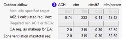
Zone ventilation flow rates and engineering checks
Zone and system min OA calculations will use the greatest value from active cells in this table.
All values are copied or derived from Zone Ventilation & Exhaust’ tab.
OA req. as makeup for EA , for example, is the volume flow rate of Outside Air (OA) required, per all relevant settings on the Zone Ventilation & Exhaust tab, as make-up for Exhaust Air (EA).
Example: If there is no Exhaust air-change requirement (box not ticked on the Ventilation… tab), then this value is zero. If there is an EA requirement, the ASHRAE 62.1 input may be used to determine this requirement in lieu of a manually entered number of air changes, etc.
The last row of the grid, Zone ventilation max/total req., displays the maximum value in each column from the rows above in all cases except when Basis for zone outside air requirement on the Ventilation… tab is set to “Sum”. When the basis is set to “Sum,” this bottom row of the Outdoor airflow grid displays the sum of the values above in each column.
Design OA percentage of max heating primary supply air
[ ] % {max OA value in table above div by Heating des airflow}
Design OA percentage of max cooling primary supply air
[ ] % {max OA value in table above div by Cooling des airflow}
Design OA percentage of min zone primary supply airflow
[ ] % {max OA value in table above div by Zone min primary airflow}
DCV to modulate OA up from reduced min when CO2 > control band min
[ cfm ] when CO2 [ > 800 ] ppm
Enabled when ‘Demand-controlled ventilation using zone CO2 sensors’ is checked on Zone Ventilation & Exhaust tab.
Reduced min value is VozA when basis for zone ventilation is ASHRAE 62.1, otherwise set according to ‘Min primary airflow at turndown’ on this tab.
CO2 ppm threshold is the min value for ‘Carbon dioxide control band’ on Zone Vent & Exhaust tab.
For DOAS (100% OA systems), when a zone has CO2-based DCV engaged and ventilation requirement set using ASHRAE 62.1, min primary airflow is set to the building component (VozA = Ra x Az/Ez) of the A62.1 requirement.
Dynamic reset of system min OA per VAV flow fractions
[ Yes | No ] Displays ‘Yes’ only when OA min reset - zn VAV flow % link is present and ‘Reset system min OA per zone VAV flow fractions to ensure %OA” is ticked on the ‘System Parameters’ tab; otherwise ‘No’.
System airside engineering checks
The following nine parameters will display Zone values for the currently selected/display layer (system = 1 zone) when Configuration = Single-zone systems or Packaged terminal units.
Total floor area and volume served
[ ] m2 [ ] m3 {both from Space Data}
Total occupants served by system (62.1 Sys Population, Ps)
[ ] people {see A62.1 calcs; = Paz if single-zone sys}
System ventilation efficiency (Ev)
[ ] {Ev = min(Evz); if single-zone system Ev = Evz ; see A62.1 sec}
Minimum OA (Vot / make-up)
[ ] l/s-person [ ] l/s [ ] l/s.m2 {mirror Vot value on Sys Parameters tab}
Maximum primary supply airflow
[ ] l/s [ ] l/s.m2 {dynamic copy of ‘System supply fan design flow rate’ values on the ‘System Parameters’ tab}
Minimum OA req. as fraction of maximum supply airflow
[ ] Derived as Vot / Maximum primary supply airflow.
This is allowed to be greater than 1.0. When that is true, parameter field is orange if no DCV and is green if there is DCV engaged for one or more zones on the system.
The orange background—used only when DCV is not engaged—flags a potential issue for users to consider. A value > 1.0 for this parameter is likely to be acceptable only in cases of extreme diversity in system loads and space occupancy. More often, if there are no DCV controls, this would be an indication of incorrect modeling of design loads and/or occupancy or may point to the need for use of the oversizing factor in the system Supply Fan component to allow for scenarios with coincident peak airflow (combined zone airflow requirements) that are greater than the peak airflow required of the system Supply Fan component during the system design loads and sizing simulation run. User judgement is required here.
The green background—used only when DCV is engaged for one or more zones on the system—is an indicator of an outcome that may be desirable, particularly for a DOAS: Because the ventilation airflow for some zones can be modulated below the full required flow rate when zone CO2 levels or occupancy are reduced, and there is diversity in terms of occupancy, a smaller system fan can deliver the necessary total volume of ventilation air. If, however, the design is intended to allow for all zones with DCV being simultaneously fully occupied and requiring the full ventilation rate, it will be necessary to define occupancy profiles accordingly. Again, user judgement is required.
Minimum primary supply airflow
[ ] l/s [ ] l/s.m2
The sum of ‘Minimum primary airflow’ for all zones.
Minimum OA req. as fraction of minimum supply airflow
[ ]
Derived as Vot / Minimum primary supply airflow .
This is allowed to be greater than 1.0. When that is true, parameter field is orange if no DCV and is green if there is DCV engaged for one or more zones on the system.
The orange background—used only when DCV is not engaged—flags a potential issue for users to consider; however, it may be acceptable in certain VAV applications. User judgement is required here.
The green background—used only when DCV is engaged for one or more zones—is an indicator of a desirable outcome: The min airflow is able to modulate below the min Design ventilation requirement to a value determined either by ASHRAE 62.1 (VozA) or by the user via the primary airflow turndown percentage for each zone (in the case of a DOAS not using A62.1).
Total exhaust airflow per zone EA req.
[ ] l/s [ ] l/s.m2
This is the sum of ‘Exhaust airflow’ for all zones served by the system, as displayed on left side of this same tab.
ASHRAE 62.1 Exhaust Requirements
|
ASHRAE 62.1 Table 6-4 Minimum Exhaust
|
|
|
|
|
|
|
|
Occupancy Category
|
Exhaust Rate,
cfm/unit
|
Exhaust Rate,
cfm/ft2
|
Exhaust Rate,
L/s*unit
|
Exhaust Rate,
L/s*ft2
|
default # of units
|
100% Transfer Air?
|
|
Arenas
|
0
|
0.50
|
0
|
2.5
|
0
|
N
|
|
Art classrooms
|
0
|
0.70
|
0
|
3.5
|
0
|
N
|
|
Auto repair rooms
|
0
|
1.50
|
0
|
7.5
|
0
|
N
|
|
Barber shops
|
0
|
0.50
|
0
|
2.5
|
0
|
N
|
|
Beauty and nail salons
|
0
|
0.60
|
0
|
3.0
|
0
|
N
|
|
Cells with toilet
|
0
|
1.00
|
0
|
5.0
|
0
|
N
|
|
Copy, printing rooms
|
0
|
0.50
|
0
|
2.5
|
0
|
N
|
|
Darkrooms
|
0
|
1.00
|
0
|
5.0
|
0
|
N
|
|
Educational science laboratories
|
0
|
1.00
|
0
|
5.0
|
0
|
N
|
|
Janitor closets, trash rooms, recycling
|
0
|
1.00
|
0
|
5.0
|
0
|
Y
|
|
Kitchenettes
|
0
|
0.30
|
0
|
1.5
|
0
|
N
|
|
Kitchens - commercial
|
0
|
0.70
|
0
|
3.5
|
0
|
N
|
|
Locker/dressing rooms
|
0
|
0.25
|
0
|
1.3
|
0
|
N
|
|
Locker rooms
|
0
|
0.50
|
0
|
2.5
|
0
|
N
|
|
Parking garages
|
0
|
0.75
|
0
|
3.7
|
0
|
N
|
|
Pet shops (animal areas)
|
0
|
0.90
|
0
|
4.5
|
0
|
N
|
|
Residential kitchens, continuous operation
|
50
|
0.00
|
25
|
0.0
|
1
|
N
|
|
Residential kitchens, non-continuous operation
|
100
|
0.00
|
50
|
0.0
|
1
|
N
|
|
Soiled laundry storage rooms
|
0
|
1.00
|
0
|
5.0
|
0
|
N
|
|
Storage rooms, chemical
|
0
|
1.50
|
0
|
7.5
|
0
|
N
|
|
Toilets - private, continuous operation
|
25
|
0.00
|
12.5
|
0.0
|
1
|
Y
|
|
Toilets - private, non-continuous operation
|
50
|
0.00
|
25
|
0.0
|
1
|
Y
|
|
Toilets - public
|
50
|
0.00
|
25
|
0.0
|
2
|
Y
|
|
Toilets - public, heavy/peak usage (e.g. school, theater, etc.)
|
70
|
0.00
|
35
|
0.0
|
2
|
Y
|
|
Woodwork shop/classrooms
|
0
|
0.50
|
0
|
2.5
|
0
|
N
|