System Modeling Fundamentals
Preparation
The speed, efficiency, and effectiveness with which an ApacheHVAC system can be set and all thermal zones assigned to it is significantly dependent upon the extent to which the model has been appropriately organized prior to doing so. Therefore, it is important to complete the following in ModelIt, before attempting to assign rooms or zones to an ApacheHVAC system:
-
Begin by using the Connect Spaces tool to couple any rooms in the model that will share a common thermostat or related means of controlling space conditions (e.g., they will all be served by a single VAV box). The resulting thermal zone will thus be represented as a single “Room” component in ApacheHVAC. This will facilitate use of multiplexing, pre-defined systems, and efficient system layout, while avoiding unnecessary complexity.
o When connecting spaces, if they will be separated by physical partitions in the actual building, these partitions should be retained, as their thermal mass and ability or receive solar gain or other radiant, conductive, and convective heat transfer will contribute to the accuracy of thermal and energy modeling.
o If any of the zones has absolute internal gains (W or Btu/h) rather than internal gains defined according to floor area (W/m2 or W/ft2), the absolute gains will have to be manually added in the composite zone. However, if they are assigned per unit floor area, no action is required, as no floor area will be lost.
-
In addition to conditioned spaces, create geometry for any other spaces or zones that will need to be represented in ApacheHVAC, such as return-air plenums (typically one per floor or as designed), underfloor air distribution (UFAD) supply plenums, thermally stratified zones, radiant heating or cooling slabs, earth tubes, solar chimneys, etc.
-
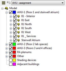
It is important to set up a Grouping Scheme in ModelIt that sorts thermal zones into groups such as System-1, -2, -3, etc. or AHU-1, -2, -3, etc. and other space types, such as Return air plenums, Solar chimney segments, Unconditioned zones, etc.
-
-
If the model includes UFAD of thermal displacement ventilation (DV), it is essential to ensure that the number and order of Stratified zones exactly matches the number and order of corresponding Occupied zones in any one AHU group. Doing so will facilitate system multiplexing, autosizing, and other fundamental aspects of system modeling. If there are some mixed (non-stratified zones) on the same system, either place them in a separate group of occupied zones or create dummy stratified zones (e.g., a series of small super-insulated boxes with no internal gains) in the model that can fill out the list of stratified zones to make it parallel the list of occupied zones on the same system. Occupied and Stratified should be in separate groups with the AHU Assignment scheme.
Efficient workflow
The following are recommended whenever starting a complex project, testing custom configurations and controls, exploring ApacheHVAC capabilities, or experimenting with HVAC strategies for a large project:
1. Start with a small model that represents what you’re exploring is the simplest terms, then save to a new name just before trying something new so that the experiment can be discarded and started over again without significant loss of investment. Many iterations with smaller models can often be more instructive and rewarding than just a few iterations with a larger model.
2. Use short simulation runs of one to three select days (very hot, very cold, should season, etc.) to explore new configurations of models and systems prior to running full annual simulations. This facilitates rapid and efficient cycles of experimentation and learning.
3. When setting up the model of the full project, combine separate rooms into thermal zones within ModelIt to the extent feasible, given the diversity of space uses, solar exposures, other loads, and the required resolution of results. All actual internal partitions should be retained. In most cases, there should be no fewer thermal zones than there will be actual thermostats in the building; however, if numerous zones are truly identical with respect to internal gains, constructions, fenestration, façade orientation, solar exposure (e.g., when local or roof shading is the same and there are no adjacent buildings), then these zones might best be further combined as “thermal blocks” (composite “rooms” in ModelIT). Again, all internal partitions should be retained.
4. If already underway with a large model and you need to test a new HVAC system configuration or controls—especially if this is a custom configuration—testing first with a small subset of the model and, again, over a short simulation period, saves time. It will provide short simulation runs and thus quick feedback for confirming and/or trouble-shooting the intended system operation.
Test simulation runs can be performed for just a few notably important or representative spaces in the model with all other zones and multiplex layers temporarily removed from the system. This significantly reduces simulation run times and bounds the experiment, improving the ease of initial analyses and detection of input and configuration errors. This can be valuable when attempting adjusted, new, complex, or innovative configurations and control strategies.
To test a new system with a simulation run for just a portion of the model, place the thermal zones that will best represent the test case—e.g., all zones on one particular HVAC air handler that is to be uniquely controlled—on a designated layer within Model-It. Then, within Model-It Layer Properties, set all other populated model layers to OFF (inactive). If there are other systems or networks in the same HVAC system file, save a copy of the file to a new name and remove all but the airside system network required for the experiment. Similarly, if a test is to be performed for just a few zones on a large system with many zones, save the HVAC file to a new name and remove all inactive zones and associated multiplex layers from the test system (the simulation will not run if there are ApacheHVAC systems referring to rooms or zone on inactive model layers).
When refinements and/or corrections to the new system and controls have been competed in this simplified context, re-introduce other building zones, systems, etc., and perform additional short simulation runs to test and refine this complete model. Finally, perform longer runs to generate needed whole-building annual results and so forth.
Room components
There are a number of important points to note with regard to the arrangement of room components in the air system and the specification of supply airflow rates:
· A “Room” in the VE is any 3D space that is to be modeled as a distinct thermal zone. This can be multiple rooms combined in ModelIt as a thermal zone, a single room, or a subdivided potion of room volume, such as a perimeter zone in an open-plan space or the occupied or stratified zone within a space served by displacement ventilation. The ApacheHVAC “Room” component can also refer to a space that would not or could not be occupied, but which plays a role in the dynamic thermal interaction with HVAC systems. Examples include a return-air plenum, an underfloor air distribution (UFAD) plenum, a segment within an earth tube, a space within a vented double-skin façade, or even a concrete slab that will be directly heated or cooled by a hydronic loop.
· It is permissible to use the same room component more than once in the air system network description, such as when more than one system supplies air to the same room. For example, consider a case where room type A has separate air supplies for heating and cooling; there may only be one actual room type A, but we can use two in the system network description - one in the heating branch and one in the cooling branch. The result is exactly the same as if you had mixed the heating and cooling supply branches together through a combining junction and supplied this mixed air to a single room type A. The use of multiple room components in this way reduces the need for large numbers of mixing and dividing junctions.
· Once the system air has entered a room component, the program assumes that the air within the room (or bounded thermal zone assigned to a room component) is fully mixed. It is not possible to differentiate between, say, air entering from a ceiling diffuser and air entering from a perimeter unit or a floor outlet. You can, if you wish, describe a single room as several room types for the purposes of the computer simulation—e.g., the core and perimeter zones of an open plan office could be described as separate room types. However, you should appreciate that there are a number of complex mechanisms of heat transfer involved in such a situation (wind, stack, and induced air movement, radiant heat exchange, etc.) and the program can only approximately analyze some of these.
· Some situations are best modeled by putting two room components in series. For example, you may wish to model a building in which the return air is extracted via the ceiling void. This can be achieved by describing the occupied space and the ceiling void as two separate room types and then connecting them in series.
