Simulation results for detailed HVAC system modeling in ApacheHVAC can be viewed and analyzed in both Vista and Vista-Pro modules. In addition to the model-level system results and more detailed room-level results, the standard Vista results view offers access to results for airside HVAC network nodes (essentially as shown in VistaPro, below) as well as node-based results for a small number of airside components.
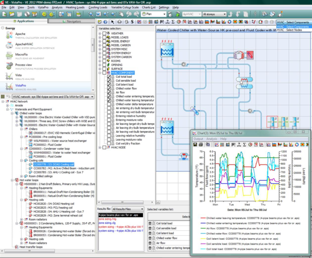
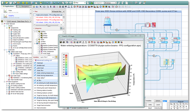
VistaPro provides access to all HVAC results, including those associated with thermal zones (rooms or other spaces in the model), nodes on the airside HVAC network, components on both airside and waterside networks, and all HVAC plant equipment.
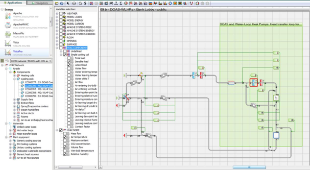
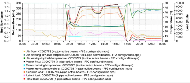
Figure 1 - 5 : Selected results for two airside network nodes and a cooling coil component in VistaPro.
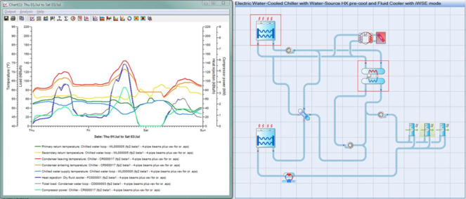
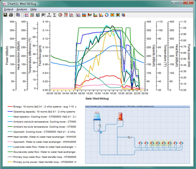
Figure 1 - 6 : Selected results for a chilled water loop, chiller, and fluid cooler in VistaPro.
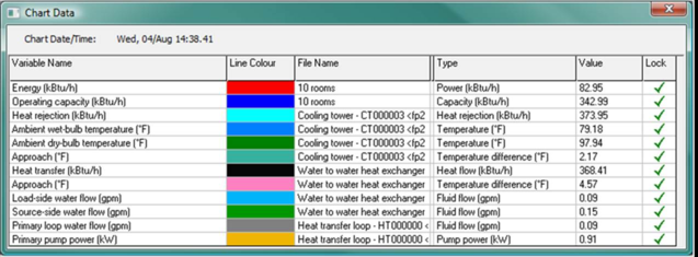
Figure 1 - 7 : Visualizing and comparing waterside HVAC component variables in VistaPro.
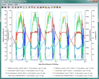
Figure 1 - 8 : Component variables can be locked via the Chart Data dialog (access by clicking the plot area) to include many details on a single plot. Above, energy and operating capacity for ten water-loop heat pumps have been plotted with select performance parameters for the heat exchanger and cooling tower used to reject heat from the heat pumps and the common heat transfer loop that couples them.