HVAC Network Editing Interface
ApacheHVAC Toolbars
The toolbars provide quick access to menu functions, selection of components and controllers to be placed on the system schematic, creation and editing of system of multiplexes, and access to system prototypes.
|
· Import HVAC networks from libraries, etc.
|
· Export HVAC networks (entire, subset, plant, etc.)
|
|
· Create multiplex
|
· Layers selected of layers in multiplex
|
|
· Edit multiplex
|
· Current multiplex display layer
|
|
· Local / global edit mode
|
· Layer up / down
|
· System schedules and setpoints
· System parameters
· Zones tabular edit view
· Global system parameter assign
· Room and zone-level sizing
· System equipment and plant sizing
· System loads, sizing, and ventilation reports
· Move
· Copy
· Query item
· Check network
· Assign zones
· Apache profiles
· Delete
· Enable/disable component tooltips
· Show/hide link for all overlays
· Show/hide overlays
· Remove all overlays
· Preferences
· Add new loop
· Edit selected loop
· Copy selected loop
· Remove selected loop
· Open loop list dialog
The three buttons shown below are toggles that open the waterside canvas and dialogs when first clicked, and return to the airside view when un-clicked:
·

Hot water loops
·

Heat transfer loops
·

Chilled water loops
HVAC Modeling Workspace
Airside network canvas
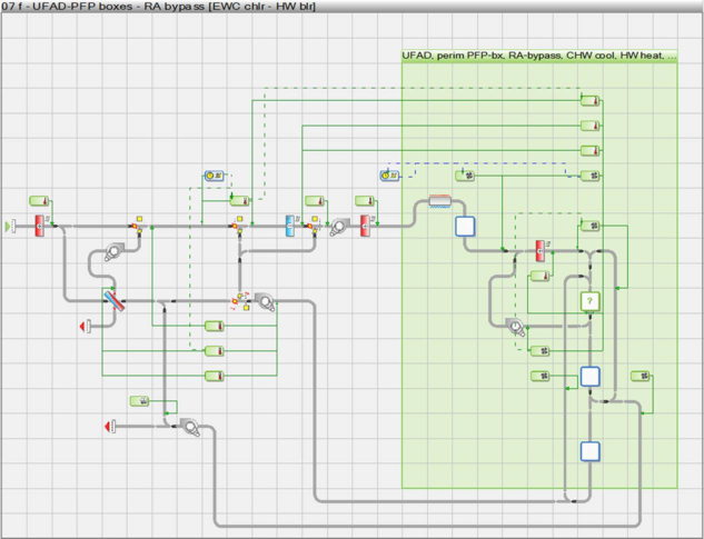
Figure 1 - 1 : The initial model workspace or canvas displays the HVAC system airside schematic and provides a graphical means of selecting, configuring, organizing, and editing airside component and controller objects. While plant equipment other than that associated with water loops is accessed while remaining in this view, this is what we refer to as the airside HVAC or airside network view.
Waterside network canvas
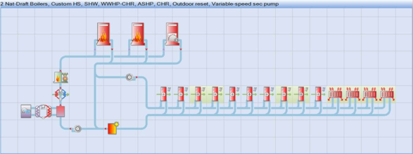
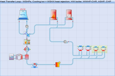
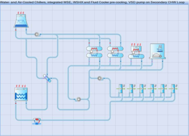
Figure 1 - 2 : There are three parallel waterside graphic views, as shown above with a range of possible options engaged. These are accessed via the three corresponding waterside loop toolbar buttons.
Component browser

Browser show/hide toolbar button.
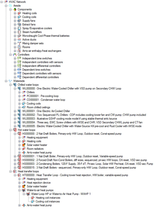
Figure 1-3: Component browser tree with HVAC network components and controllers.
The component browser provides a listing of all components in the current ApacheHVAC file. This can be used to locate and/or select a particular type of component or controller within a large or complex HVAC network. Selecting the component or controller within the browser causes it to be highlighted on the network in the model space. The browser can also be useful in determining how many of a particular component or controller type are present.
It is not necessary to hide the component browser for most HVAC system networks, as the speed of this has been significantly improved over earlier versions. When working on exceptionally large or complex HVAC networks, if the opening of component and controller dialogs does begin to slow noticeably, the component browser can be turned OFF by clicking the browser show/hide button on the toolbar. This will further increase the speed with which component and controller dialogs open.
Mouse controls
The left mouse button is used for selecting and placing component and controllers. When placing these, the current selection persists until cancelled by clicking the right mouse button. The mouse scroll wheel can be used to zoom in and out of the systems view. The pan function accessed provided by moving the mouse while depressing the scroll wheel.
Mouse/key operations summary
The combined keyboard and mouse actions described in the left column below can be used to complete the corresponding operations listed in all capital letters in the right column.
Selected airside network objects
Drag MOVE
Ctrl + Drag COPY
Ctrl-C COPY TO CLIPBOARD
Ctrl-V PASTE FROM CLIPBOARD (within current HVAC session)
Elements of a selected controller (applies only when a single controller is selected)
Click & Drag MOVE NODE (round sensor bulb or control lead end with arrowhead)
Shift + Drag MOVE CONTROL BOX
DURING “PENCIL” DRAWING
Click on object or in blank cell START NEW PATH
Click object after starting path CONNECT or CREATE JUNCTION
Click bare end after starting path CONNECT or CREATE JUNCTION
Click bare end after starting path CREATE CUSP or 90° BEND
Double-click in a blank cell TERMINATE CURRENT PATH (as bare end)
Ctrl-Z (up to 10 times) UNDO SECTION to PREVIOUS CUSP/OBJECT