Linear take-off conventions
Linear non-repeating bridge lengths are automatically ‘taken-off’ the model based on:
-
-
-
-
Surface or opening level.
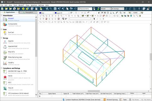
The automatically generated non-repeating bridge junction locations & identified type can be inspected in Model-iT using the Model-iT View menu feature Show thermal bridging. This view option should be used for checking the junction locations and not left ON as it slows redrawing of the model.
Fig : Model-iT Show Thermal bridging feature
This display mode will show the vertexes coloured by thermal bridging type:
-
Roof (transition) - orange
-
Roof-wall (parapet) - magenta
-
Roof (int wall) - light blue
-
Wall-partition (int wall) - light blue
-
Wall-wall (corner) - dark orange
-
Wall-ground floor (ground floor) - green
-
Wall-floor (not ground/ intermediate floor) - yellow
-
Lintel above window / door - yellow
-
Jamb at window / door - light blue
-
Sill below window / door - green
-
Rooflight kerb - dark blue
-
Random (all types) - black
-
All other vertices i.e. not an identified thermal bridge - light grey
Users can use this display mode to decide if further bespoke non-repeating thermal bridges are required - these can be added using the random thermal bridge tools.
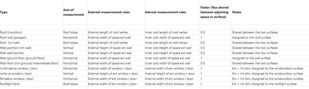
The Type shared flux factor determines the division of the heat flux when a junction occurs between two surfaces. This only applies at surface level and not at opening level.
For each transition type, the factor that is applied and how the heat flow is attributed when a junction occurs between two surfaces.
For example, for an external wall corner the heat flow is attributed equally between the two surfaces. However, for windows, doors and rooflights the whole heat flow is assigned to that opening surface for reporting purposes (rather than add it to the parent surface and lose this resolution in the data).
Fig: Linear take-off conventions
In the situation of an internal partition with a hole meeting an external wall surface: whenever we have an edge that fully matches the edge of a hole (i.e. same height) and this edge would otherwise be an internal partition to external wall junction, we do not add the thermal bridge.
In situations where room geometry does not align e.g. partitions in stacked rooms, the internal dimension of a shared thermal bridge e.g. a floor non-repeating bridge, will be different depending on which room the internal dimension is taken-off. In such situations the automatic take-off rules will choose the longest dimension for the shared thermal bridge. This has been chosen mindful of the tolerances and the need to make a conservative assessment.
In VistaPro Linear thermal bridging is collated up the object levels – surface > room breakdown > room totals. This assignment approach allows the user to explore the source of thermal bridging by quanta.