The water-to-air heat pump component, along with the heat transfer loop to which it must be connected, facilitates modeling a complete water-to-air heat pump (WAHP) system with various options for system-level heat acquisition and rejection.
A water-to-air heat pump system consists of multiple zone-level water-to-air heat pumps connected to a common water loop. The common water loop is used by each individual heat pump as a source for acquiring heat or sink for rejecting heat. Some of the WAHP units on the loop may be in cooling mode, while others may be in heating mode. For all WAHP units on given Heat transfer loop, this common loop simultaneously acts a resource for any WAHP in heating mode and a sink for any AWHP in cooling mode.
Two components are provided to facilitate the simulation of a WAHP system:
· Water-to-air heat pump
· Heat transfer loop
Details of the Heat transfer loop component are covered in section 2.8. This section covers the details of the Water-to-air heat pump component.
The water-to-air heat pump needs to be defined in two levels:
· Parameters characterizing WAHP performance are set at the ‘type’ level within the Water-to-air heat pumps (types) dialog.
· Parameters specific to the capacity and other sizing characteristics of WAHP performance are set at the ‘instance’ level within the coil dialogs (i.e., coil and load-side sizing-related performance is determined separately for each application instance of a referenced type).
A WAHP for heating is modeled by defining a WAHP ‘type’ serving a simple heating coil with its System type set to WAHP. A WAHP for cooling is modeled by defining a WAHP ‘type’ serving a simple cooling coil with its System type set to WAHP.
A WAHP that will operate in both heating and cooling modes is modeled by defining a WAHP ‘type’ and referencing this same type within both the heating coil and a cooling coil dialogs by selecting WAHP from the System type list. During simulation, when the WAHP is serving a heating coil, the heating performance curves are used; when serving a cooling coil, the cooling performance curves are used.
While a WAHP providing both heating and cooling is modeled as serving separate heating and cooling coils, in reality these would be a single physical coil. Because we’re simulating and sizing two separate components, it is up to the user ensure that heating and cooling coils which are in reality one and the same are assigned the same WAHP type and the same HTL (the water source).
The WAHP models the heat pump compressor power consumption, but not the indoor (supply) fan power consumption, which must be modeled separately using a fan component on the HVAC airside network.
The WAHP units must be connected to (served by) a common Heat Transfer Loop (HTL) by selecting the appropriate HTL within the heating/cooling coil dialogs.
Heat sources (or sinks) available on the heat transfer loop may include the following:
-
For heating: solar water heater (SWH), water source heat exchanger (WSHX), condenser heat recovery (CHR), air-to-water heat pump (AWHP), combined heat and power (CHP), sequenced heating equipment set
-
For cooling: water source heat exchanger (WSHX), cooling tower (CT) or fluid cooler (FC)
Note that the ground-water heat pump implementation in this phase is intended for modeling ambient- and ground-water sources (oceans, rivers, lakes, ground water, wells, etc.) with a constant or readily profiled water temperature. If you choose to use this component to model a ground loop above the water table (i.e., a “geo-thermal heat exchanger”), please be aware that this will not include a dynamic model of the ground mass as a source and sink to be thermally depleted and recharged over time. For more detailed modeling of ground-source heat pump systems, including characteristics of bore fields and geo-thermal heat exchangers, see Appendix D: Ground-Source Heat Pump Modeling using ApacheHVAC loads and Gaia Geothermal Ground-Loop Design.
Water-to-air heat pump model
The water-to-air heat pump model simulates the refrigerant side of a water-to-air heat pump. The water-to-air heat pump airside (the cooling coil (evaporator) or the heating coil (condenser)) is modeled with the current ApacheHVAC simple heating/cooling coil model, using the total available water-to-air heat pump capacity calculated by the water-to-air heat pump performance curves. This model uses default or user-defined water-to-air heat pump performance characteristics at rated conditions and six performance curves to determine water-to-air heat pump performance at off-rated conditions.
The six water-to-air heat pump performance curves are (three for heating, three for cooling):
· Water-to-air heat pump heating capacity (temperature dependence) curve
· Water-to-air heat pump heating electric input ratio (EIR) (temp dependence) curve
· Water-to-air heat pump heating electric input ratio (EIR) (part-load dependence) curve
· Water-to-air heat pump cooling capacity (temperature dependence) curve
· Water-to-air heat pump cooling electric input ratio (EIR) (temp dependence) curve
· Water-to-air heat pump cooling electric input ratio (EIR) (part-load dependence) curve
The water-to-air heat pump model includes the heat pump compressor power consumption, but not the indoor (supply) fan power consumption. Supply fans for water-to-air heat pump systems must be modeled separately as an ApacheHVAC fan component.
Water-to-air heat pump model description
The following information can be accessed via the WAHP model description button in the water-to-air heat pump dialog. It describes the variables and some of the fundamental relationships in the water-to-air heat pump model.
· Entering coil wet-bulb temperature: Tewb
· Entering coil dry-bulb temperature: Tedb
· Entering water temperature: Tewt
· Rated cooling capacity: Qcrat
· Rated cooling coefficient of performance: COPcrat
· Variable cooling capacity: Qccap = Qcrat fCAPtt(Tewb,Tewt)
· Cooling load: Qc
· Cooling part-load ratio: pc = Qc / Qccap
· Cooling Electric Input Ratio: EIRc = fEIRtt(Tewb, Tewt) fEIRp(pc) / (pc COPcrat)
· Cooling power: Wc = EIRc Qc
· Rated heating capacity: Qhrat
· Rated heating coefficient of performance: COPhrat
· Variable heating capacity: Qhcap = Qhrat fCAPtt(Tedb,Tewt)
· Heating load: Qh
· Heating part-load ratio: ph = Qh / Qhcap
· Heating Electric Input Ratio: EIRh = fEIRtt(Tedb, Tewt) fEIRp(ph) / (ph COPhrat)
· Heating power: Wh = EIRh Qh
Rated condition and Design condition
The rated condition is the basis for the calculation of water-to-air heat pump performance at simulation time. The rated condition is normally the ARI rating condition or equivalent in locations where other equipment rating standards apply—i.e., this is the condition at which the water-to-air heat pump characteristics are specified by a manufacturer. However, it can optionally be the design condition.
The design condition, on the other hand, is the condition at the time of peak design heating/cooling load.
The default rated and design condition data are based on the standard ARI conditions ( ANSI/ARI/ASHRAE ISO Standard 13256-1: 1998 ).
Except for rated capacity, rated condition data should be entered or edited on the WAHP ‘type’ level, in the Rated condition tab of the Water-to-air heat pump dialog.
Design condition data, together with rated capacity, should be entered or edited on the WAHP ‘instance’ level, in the simple heating/cooling coil dialogs with their ‘System type’ selected as Water-to-air heat pump.
To use catalogue water-to-air heat pump data, enter a heating/cooling capacity and COP at the rated condition and read the derived capacity and COP at the design condition.
Under normal conditions, Design heating/cooling capacity and COP in the simple heating/cooling coil dialog are derived based upon the following parameters:
· Selected Heating/Cooling performance curves (from the WAHP type )
· Rated Heating/Cooling capacity (from the WAHP instance)
· Rated Heating/Cooling COP (from the WAHP type)
· Rated Entering coil dry-bulb (or wet-bulb) temperature (from the WAHP type)
· Rated Entering water temperature (from the WAHP type)
· Design Entering coil dry-bulb (or wet-bulb) temperature (from the WAHP instance)
· Design Entering water temperature (from the WAHP instance)
In the special case of updating parameters for the simple heating/cooling coils served by WAHP after autosizing, Design heating/cooling capacity and Design entering coil dry-bulb (or wet-bulb) temperature are firstly updated with the autosized WAHP coil capacity and the entering coil dry-bulb (or wet-bulb) temperature value accompanying the autosized capacity. Rated capacity and Design COP are then derived using the updated Design capacity and Design entering coil dry-bulb (or wet-bulb) temperature, together with performance curves and other rated and design parameters that are not updated by the autosizing process.
Water-to-air heat pump sizing procedure
As the WAHP data correspond to the ‘size’ of the WAHP are defined and stored on the ‘instance’ level (in the simple heating/cooling coil dialog), only the instance level (size) parameters need to be updated during system sizing. Therefore, WAHP instance sizing is covered by the normal sizing process for its connected simple heating and cooling coil. No additional sizing process is needed for the WAHP types.
When updating parameters for the simple heating/cooling coils served by WAHP after autosizing, Design heating/cooling capacity and Design entering coil dry-bulb (or wet-bulb) temperature are firstly updated with the autosized WAHP coil capacity and the entering coil dry-bulb (or wet-bulb) temperature value accompanying the autosized capacity. Rated capacity and Design COP are then derived using the updated Design capacity and Design entering coil dry-bulb (or wet-bulb) temperature, together with selected performance curves for the WAHP type and other rated and design parameters that are not updated by the autosizing process.
Water-to-air heat pump type level data
The water-to-air heat pump ‘type’ level parameters are accessed through the Water-to-air heat pump (types) dialog and the Water-to-air heat pump dialog. These parameters determine the shape of the performance characteristics of a water-to-air heat pump.
Water-to-air heat pump (types) dialog
The water-to-air heat pump ‘type’ level parameters are accessed through the Water-to-air heat pump (types) tool, which facilitates adding, editing, copying and removing named water-to-air heat pump types.
Water-to-air heat pump types are accessed through the toolbar button shown below.

Toolbar button for Water-to-air heat pump (types) list.
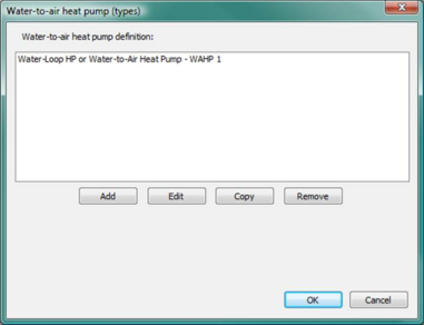
Clicking this toolbar button opens up the ‘ Water-to-air heat pump (types) ’ dialog (shown in Figure 2-46), which manages a set of water-to-air heat pump types . A water-to-air heat pump type may be added, edited, copied or removed through the corresponding buttons in this dialog. Double clicking on an existing water-to-air heat pump type (or clicking the ‘Edit’ button after selection of an existing water-to-air heat pump type ) opens up the ‘ water-to-air heat pump ’ dialog (shown in Figure 2-47), where parameters for a water-to-air heat pump type may be edited.
Water-to-air heat pump dialog
Figure 3 - 52 : Water-to-air heat pump (types) dialog
The entities defined here are types. A single water-to-air heat pump type may be assigned to many simple heating or cooling coils.
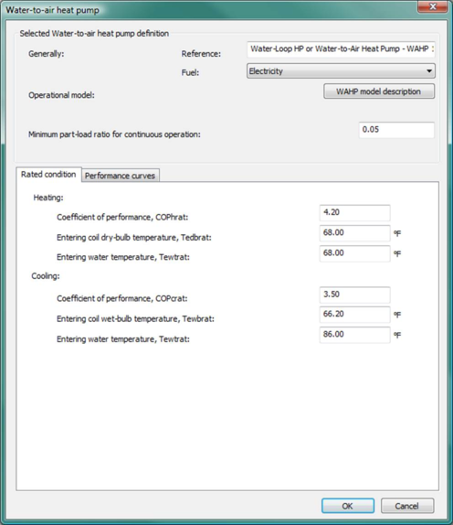
Figure 3 - 53 : Water-to-air heat pump edit dialog (shown with the Rated condition sub-tab selected) (screenshot to be added)
The water-to-air heat pump dialog contains the ‘type’ level parameters for a water-to-air heat pump. It provides editing access to the parameters and inputs fields that determine the shape of the performance characteristics of a water-to-air heat pump.
Reference name
Enter a descriptive name for the water-to-air heat pump type. The reference is for your use when referencing the current water-to-air heat pump type within component and controller dialogs. References can be valuable in organizing and navigating the system and when the system model is later re-used on another project or passed on to another modeler. Reference names should thus be informative with respect to differentiating similar equipment, components, and controllers.
Fuel
Select the “fuel” or energy source used by the water-to-air heat pump type to determine the category for reporting energy consumption results. For scratch-built system models, this should normally be set to “Electricity”.
Operational model: WAHP model description
Click the WAHP model description button for description of model variables and fundamental relationships.
Minimum part-load ratio for continuous operation
Enter the part-load ratio (fraction of 1.0) below which the compressor should cycle on/off to meet the load rather than operate continuously.
Rated condition
Except for rated capacity, rated condition data are entered or edited on the WAHP ‘type’ level, in the Rated condition tab of the Water-to-air heat pump dialog. There are two sets of rated condition data required, one for heating and one for cooling.
Coefficient of performance (COP)
Enter the heating/cooling COP at the Rated condition. This is the ratio of heating/cooling capacity to the electric energy required to provide this heating/cooling output at the rated condition. This value is used both in simulation and to calculate COP at the Design condition.
Entering coil dry-bulb (wet-bulb) temperature
Enter the entering coil dry-bulb or wet-bulb temperature as seen by the WAHP air-side (load-side) at the rated condition.
For heating, enter the entering coil dry-bulb temperature at the rated condition.
For cooling, enter the entering coil wet-bulb temperature at the rated condition.
Entering water temperature
Enter the entering water temperature as seen by the WAHP water-side (source-side) at the rated condition.
Performance curves
Water-to-air heat pump performance curves are selected or edited on the WAHP ‘type’ level, in the Performance curves tab of the Water-to-air heat pump dialog. There are six performance curves required, three for heating and three for cooling.
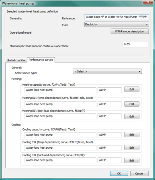
Figure 3 - 54 : Water-to-air heat pump edit dialog (shown with the Performance curve sub-tab selected)
Performance curve selection
Performance curves for a specific WAHP type are selected through the Select curve type (< Select >) dropdown list. Selecting a particular curve set from this single drop-down selection box populates the all six heating and cooling curve below it for the chosen heat pump type or category.
· WLHP – appropriate to conventional systems using a boiler and cooling tower for heat addition and rejection on the heat transfer loop.
· GWHP – appropriate for systems using a typical ground-water, well, lake, or ocean water as the primary source and sink for heat addition and rejection on the heat transfer loop.
Heating capacity curve
Using the drop-down <Select> menu, choose the most appropriate pre-defined Heating capacity performance curve for the type of system you are modeling.
Advanced users: The Edit button provides access to editing the performance curve coefficients and other associated performance parameters. A separate section on Water-to-air heat pump performance curves details and editing is provided below.
Heating EIR temperature dependence curve
Using the drop-down <Select> menu, choose the most appropriate pre-defined temperature dependence performance curve for the type of system you are modeling.
Advanced users: The Edit button provides access to editing the performance curve coefficients and other associated performance parameters. A separate section on Water-to-air heat pump performance curves details and editing is provided below.
Heating EIR part-load dependence curve
Using the drop-down <Select> menu, choose the most appropriate pre-defined part-load dependence performance curve for the type of system you are modeling.
Advanced users: The Edit button provides access to editing the performance curve coefficients and other associated performance parameters. A separate section on Water-to-air heat pump performance curves details and editing is provided below.
Cooling capacity curve
Using the drop-down <Select> menu, choose the most appropriate pre-defined Cooling capacity performance curve for the type of system you are modeling.
Advanced users: The Edit button provides access to editing the performance curve coefficients and other associated performance parameters. A separate section on Water-to-air heat pump performance curves details and editing is provided below.
Cooling EIR temperature dependence curve
Using the drop-down <Select> menu, choose the most appropriate pre-defined temperature dependence performance curve for the type of system you are modeling.
Advanced users: The Edit button provides access to editing the performance curve coefficients and other associated performance parameters. A separate section on Water-to-air heat pump performance curves details and editing is provided below.
Cooling EIR part-load dependence curve
Using the drop-down <Select> menu, choose the most appropriate pre-defined part-load dependence performance curve for the type of system you are modeling.
Advanced users: The Edit button provides access to editing the performance curve coefficients and other associated performance parameters. A separate section on Water-to-air heat pump performance curves details and editing is provided below.
Water-to-air heat pump instance level data
The water-to-air heat pump ‘instance’ level parameters are accessed through the WAHP-served simple heating and cooling coils. These parameters determine the size of the performance characteristics of a water-to-air heat pump.
WAHP heating ‘instance’ level parameters can be edited in the simple heating coil dialog, which has a System type selected as water-to-air heat pump.
WAHP cooling ‘instance’ level parameters can be edited in the simple cooling coil dialog, which has a System type selected as water-to-air heat pump.
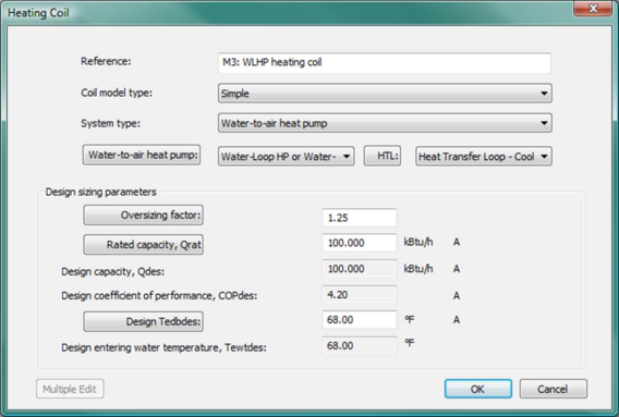
Figure 3 - 55 : Simple heating coil dialog (shown with System type selected as water-to-air heat pump)
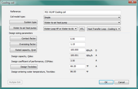
Figure 3 - 56 : Simple cooling coil dialog (shown with System type selected as water-to-air heat pump)
Water-to-air heat pump data in Simple heating coil dialog
WAHP heating ‘instance’ level parameters can be edited in the simple heating coil dialog, which has a System type selected as water-to-air heat pump.
In addition to some parameters that are common to simple heating coils served by other system types (hot water loop, etc.), a WAHP-served simple heating coil has the following special parameters required by the water-to-air heat pump system type.
Water-to-air heat pump
Select the water-to-air heat pump type that is used to serve this simple heating coil, from the Water-to-air heat pump dropdown list, which will list all WAHP types that have been defined in the system. The WAHP type determines the shape of the performance characteristics of a water-to-air heat pump.
HTL (Heat Transfer Loop)
Select the heat transfer loop that is connected to the water-side (source-side) of this WAHP-served simple heating coil, from the HTL dropdown list, which will list all heat transfer loops that have been defined in the system. The selected HTL will be the heating source of this WAHP instance.
Rated capacity, Qrat
Enter the WAHP heating capacity at the Rated condition. This value is used both in simulation and to calculate heating capacity at the Design condition.
This parameter is autosizable. When this parameter is autosized, its value in the field and its autosizing label ‘A’ becomes green.
Design capacity, Qdes
Normally, design heating capacity is automatically derived using performance curves and rated parameters for the selected WAHP type and other rated and design parameters provided in this dialog.
In the special case of updating parameters for the simple heating coils served by WAHP after autosizing, Design heating capacity and Design entering coil dry-bulb temperature are firstly updated with the autosized WAHP coil capacity and the entering coil dry-bulb temperature value accompanying the autosized capacity. Rated capacity and Design COP are then derived using the updated Design capacity and Design entering coil dry-bulb temperature, together with performance curves and other rated and design parameters that are not updated by the autosizing process.
This parameter is autosizable. When this parameter is autosized, its value in the field and its autosizing label ‘A’ becomes green.
Design coefficient of performance, COPdes
Design coefficient of performance (COP) is the ratio of design heating capacity to the electric energy required to provide this heating output at the design condition. This value is automatically derived using performance curves and rated parameters for the selected WAHP type and other rated and design parameters provided in this dialog.
This parameter is autosizable. When this parameter is autosized, its value in the field and its autosizing label ‘A’ becomes green.
Design entering coil dry-bulb temperature, Tedbdes
Enter the entering coil dry-bulb temperature as seen by the WAHP air-side (load-side) at the design condition.
This parameter is autosizable. When this parameter is autosized, its value in the field and its autosizing label ‘A’ becomes green.
Design entering water temperature, Tewtdes
This is the entering water temperature as seen by the WAHP water-side (source-side) at the design condition. It is always set to be a dynamic copy of the Design heating supply water temperature from the connected heat transfer loop (from the Temperature control tab of the HTL dialog), and is not editable.
Water-to-air heat pump data in Simple cooling coil dialog
WAHP cooling ‘instance’ level parameters can be edited in the simple cooling coil dialog, which has a System type selected as water-to-air heat pump.
In addition to some parameters that are common to simple cooling coils served by other system types (chilled water loop, etc.), a WAHP-served simple cooling coil has the following special parameters required by the water-to-air heat pump system type.
Water-to-air heat pump
Select the water-to-air heat pump type that is used to serve this simple cooling coil, from the Water-to-air heat pump dropdown list, which will list all WAHP types that have been defined in the system. The WAHP type determines the shape of the performance characteristics of a water-to-air heat pump.
HTL (Heat Transfer Loop)
Select the heat transfer loop that is connected to the water-side (source-side) of this WAHP-served simple cooling coil, from the HTL dropdown list, which will list all heat transfer loops that have been defined in the system. The selected HTL will be the cooling source of this WAHP instance.
Rated capacity, Qrat
Enter the WAHP cooling capacity at the Rated condition. This value is used both in simulation and to calculate cooling capacity at the Design condition.
This parameter is autosizable. When this parameter is autosized, its value in the field and its autosizing label ‘A’ becomes green.
Design capacity, Qdes
Normally, design cooling capacity is automatically derived using performance curves and rated parameters for the selected WAHP type and other rated and design parameters provided in this dialog.
In the special case of updating parameters for the simple cooling coils served by WAHP after autosizing, Design cooling capacity and Design entering coil wet-bulb temperature are firstly updated with the autosized WAHP coil capacity and the entering coil wet-bulb temperature value accompanying the autosized capacity. Rated capacity and Design COP are then derived using the updated Design capacity and Design entering coil wet-bulb temperature, together with performance curves and other rated and design parameters that are not updated by the autosizing process.
This parameter is autosizable. When this parameter is autosized, its value in the field and its autosizing label ‘A’ becomes green.
Design coefficient of performance, COPdes
Design coefficient of performance (COP) is the ratio of design cooling capacity to the electric energy required to provide this cooling output at the design condition. This value is automatically derived using performance curves and rated parameters for the selected WAHP type and other rated and design parameters provided in this dialog.
This parameter is autosizable. When this parameter is autosized, its value in the field and its autosizing label ‘A’ becomes green.
Design entering coil wet-bulb temperature, Tewbdes
Enter the entering coil wet-bulb temperature as seen by the WAHP air-side (load-side) at the design condition.
This parameter is autosizable. When this parameter is autosized, its value in the field and its autosizing label ‘A’ becomes green.
Design entering water temperature, Tewtdes
This is the entering water temperature as seen by the WAHP water-side (source-side) at the design condition. It is always set to be a dynamic copy of the Design cooling supply water temperature from the connected heat transfer loop (from the Temperature control tab of the HTL dialog), and is not editable.
Water-to-air heat pump performance curves: details and editing
Heating Capacity curve, fCAPtt(Tedb,Tewt), details and editing
Use the Edit button to view and edit the curve parameters. The Curve Editing dialog displays the formula and parameters of the curve and provides for editing of the curve parameters. You are permitted to edit the curve coefficients and the applicable ranges of the independent variables.
When editing the curve parameters, it is important that you understand the meaning of the curve and its usage in the model algorithm.
Ensure that the edited curve has reasonable ranges for the independent variables. A performance curve is valid only within its applicable ranges. If the independent variables are outside of the ranges that you set, the specified variable limits (maximum or minimum values) will be used.
Figure 3 - 57 : Edit dialog for the water-to-air heat pump heating capacity curve
The cooling capacity curve f CAPtt (T edb, T ewt ) is a bi-quadratic function of
tedb = T edb – Tdatum
tewt = T ewt – Tdatum
where
T edb = entering coil dry-bulb temperature.
T ewt = entering water temperature.
T datum = datum temperature (0°C or 0°F), introduced for the convenience of units conversion of the curve coefficients.
And:
fCAPtt(T edb , T ewt ) = (C00 + C10 tedb + C20 tedb 2 + C01 tewt + C02 tewt 2 + C11 tedb tewt) / Cnorm
where
C 00 , C 10 , C 20 , C 01 , C 02 and C 11 are the curve coefficients
C norm is adjusted (by the program) to make f CAPtt (T edbrat, T ewtrat ) = 1
T edbrat = rated entering coil dry-bulb temperature.
T ewtrat = rated entering water temperature.
The heating capacity curve is evaluated at each time step during the simulation. The curve value is multiplied by the rated cooling capacity (Q rat ) to get the available (full-load) heating capacity (Q cap ) of the current time step, for the specific T edb and T ewt temperatures:
Qcap = Qrat fCAPtt(T edb , T ewt )
The curve should have a value of 1.0 when the temperatures are at rated conditions.
Heating EIR Temperature Dependence curve, fEIRtt(Tedb,Tewt), details and editing
Use the Edit button to view and edit the curve parameters. The Curve Editing dialog displays the formula and parameters of the curve and provides for editing of the curve parameters. You are permitted to edit the curve coefficients and the applicable ranges of the independent variables.
When editing the curve parameters, it is important that you understand the meaning of the curve and its usage in the model algorithm.
Ensure that the edited curve has reasonable ranges for the independent variables. A performance curve is valid only within its applicable ranges. If the independent variables are outside of the ranges that you set, the specified variable limits (maximum or minimum values) will be used.
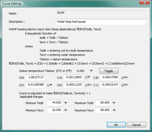
Figure 3 - 58 : Edit dialog for the water-to-air heat pump heating EIR temperature dependence curve
The heating EIR (temperature dependence) curve f EIRtt (T edb , T ewt ) is a bi-quadratic function of
tedb = T edb – Tdatum
tewt = T ewt – Tdatum
where
T edb = entering coil dry-bulb temperature.
T ewt = entering water temperature.
T datum = datum temperature (0°C or 0°F), introduced for the convenience of units conversion of the curve coefficients.
And:
fEIRtt(T edb , T ewt ) = (C00 + C10 tedb + C20 tedb 2 + C01 tewt + C02 tewt 2 + C11 tedb tewt) / Cnorm
where
C 00 , C 10 , C 20 , C 01 , C 02 and C 11 are the curve coefficients
C norm is adjusted (by the program) to make f EIRtt (T edbrat, T ewtrat ) = 1
T edbrat = rated entering coil dry-bulb temperature.
T ewtrat = rated entering water temperature.
The heating EIR (temperature dependence) curve is evaluated at each time step during the simulation. The curve value is multiplied by the rated EIR (= 1/ COP rat , where COP rat is the rated coefficient of performance) to get the full-load EIR of the current time step, for the specific T edb and T ewt temperatures. The curve should have a value of 1.0 when the temperatures are at rated conditions.
Heating EIR Part-load Dependence curve, fEIRp(p), details and editing
Use the Edit button to view and edit the curve parameters. The Curve Editing dialog displays the formula and parameters of the curve and provides for editing of the curve parameters. You are permitted to edit the curve coefficients and the applicable ranges of the independent variables.
When editing the curve parameters, it is important that you understand the meaning of the curve and its usage in the model algorithm.
Ensure that the edited curve has reasonable ranges for the independent variables. A performance curve is valid only within its applicable ranges. If the independent variables are outside of the ranges that you set, the specified variable limits (maximum or minimum values) will be used.
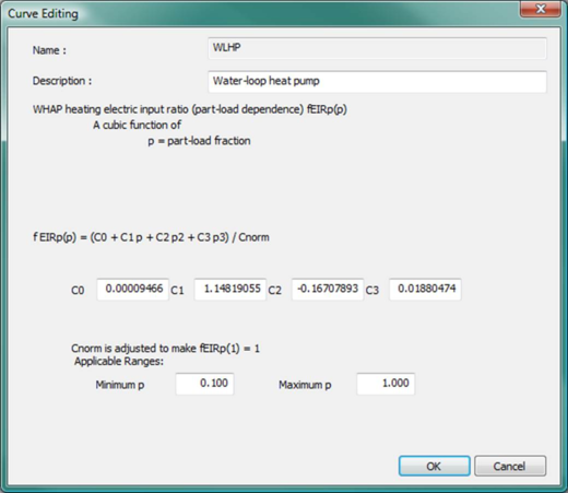
Figure 3 - 59 : Edit dialog for the water-to-air heat pump heating EIR part-load dependence curve
The cooling EIR (part-load dependence) curve f EIRp (p) is a bi-quadratic function of
p = Q/Q cap
where
p = part-load fraction
Q = heating load
Q cap = available (full-load) heating capacity
And:
f EIRp (p) = (C 0 + C 1 p + C 2 p 2 + C 3 p 3 ) / C norm
where
C 0 , C 1 , C 2 , and C 3 are the curve coefficients,
C norm is adjusted (by the program) to make f EIRp (1) = 1
The cooling EIR (part-load dependence) curve is evaluated at each time step during the simulation. The curve value is multiplied by the rated EIR (= 1/ COP rat , where COP rat is the rated coefficient of performance) and the EIR (temperature dependence) curve value to get the EIR of the current time step, for the specific T edb and T ewt temperatures and the specific part load ratio at which the WAHP unit is operating:
EIR = f EIRtt (T edb, T ewt ) f EIRp (p) / (pCOP rat )
The curve should have a value of 1.0 when the part load ratio equals 1.0 and the temperatures are at rated conditions.
A note on the applicable range of part-load ratio p:
The minimum p is used by the program as the minimum unloading ratio, where the WAHP unit capacity can no longer be reduced by normal unloading mechanism and the WAHP unit must be false loaded to meet smaller loads. A typical false loading strategy is hot-gas bypass. If this is the false loading strategy used by the WAHP unit, the minimum p is the part load ratio at which hot gas bypass starts.
The maximum p should usually be 1.0. During the simulation, a part-load ratio greater than 1.0 is a sign of WAHP units undersizing.
Cooling Capacity curve, fCAPtt(Tewb,Tewt), details and editing
Use the Edit button to view and edit the curve parameters. The Curve Editing dialog displays the formula and parameters of the curve and provides for editing of the curve parameters. You are permitted to edit the curve coefficients and the applicable ranges of the independent variables.
When editing the curve parameters, it is important that you understand the meaning of the curve and its usage in the model algorithm.
Ensure that the edited curve has reasonable ranges for the independent variables. A performance curve is valid only within its applicable ranges. If the independent variables are outside of the ranges that you set, the specified variable limits (maximum or minimum values) will be used.
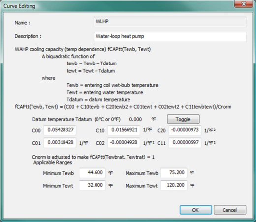
Figure 3 - 60 : Edit dialog for the water-to-air heat pump cooling capacity curve
The cooling capacity curve f CAPtt (T ewb, T ewt ) is a bi-quadratic function of
tewb = T ewb – Tdatum
tewt = T ewt – Tdatum
where
T ewb = entering coil wet bulb temperature.
T ewt = entering water temperature.
T datum = datum temperature (0°C or 0°F), introduced for the convenience of units conversion of the curve coefficients.
And:
fCAPtt(T ewb , T ewt ) = (C00 + C10 tewb + C20 tewb 2 + C01 tewt + C02 tewt 2 + C11 tewb tewt) / Cnorm
where
C 00 , C 10 , C 20 , C 01 , C 02 and C 11 are the curve coefficients
C norm is adjusted (by the program) to make f CAPtt (T ewbrat, T ewtrat ) = 1
T ewtrat = rated entering water temperature.
T ewbrat = rated entering coil wet bulb temperature.
The cooling capacity curve is evaluated at each time step during the simulation. The curve value is multiplied by the rated cooling capacity (Q rat ) to get the available (full-load) cooling capacity (Q cap ) of the current time step, for the specific T ewb and T ewt temperatures:
Qcap = Qrat fCAPtt(T ewb , T ewt )
The curve should have a value of 1.0 when the temperatures are at rated conditions.
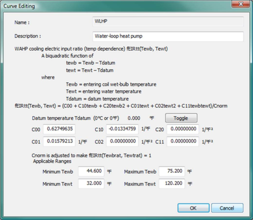
Cooling EIR Temperature Dependence curve, fEIRtt(Tewb,Tewt), details and editing
Use the Edit button to view and edit the curve parameters. The Curve Editing dialog displays the formula and parameters of the curve and provides for editing of the curve parameters. You are permitted to edit the curve coefficients and the applicable ranges of the independent variables.
When editing the curve parameters, it is important that you understand the meaning of the curve and its usage in the model algorithm.
Ensure that the edited curve has reasonable ranges for the independent variables. A performance curve is valid only within its applicable ranges. If the independent variables are outside of the ranges that you set, the specified variable limits (maximum or minimum values) will be used.
Figure 3 - 61 : Edit dialog for the water-to-air heat pump cooling EIR temperature dependence curve
The cooling EIR (temperature dependence) curve f EIRtt (T ewb , T ewt ) is a bi-quadratic function of
tewb = T ewb – Tdatum
tewt = T ewt – Tdatum
where
T ewb = entering coil wet bulb temperature.
T ewt = entering water temperature.
T datum = datum temperature (0°C or 0°F), introduced for the convenience of units conversion of the curve coefficients.
And:
fEIRtt(T ewb , T ewt ) = (C00 + C10 tewb + C20 tewb 2 + C01 tewt + C02 tewt 2 + C11 tewb tewt) / Cnorm
where
C 00 , C 10 , C 20 , C 01 , C 02 and C 11 are the curve coefficients
C norm is adjusted (by the program) to make f EIRtt (T ewbrat, T ewtrat ) = 1
T ewtrat = rated entering water temperature.
T ewbrat = rated entering coil wet bulb temperature.
The cooling EIR (temperature dependence) curve is evaluated at each time step during the simulation. The curve value is multiplied by the rated EIR (= 1/ COP rat , where COP rat is the rated coefficient of performance) to get the full-load EIR of the current time step, for the specific T ewb and T ewt temperatures. The curve should have a value of 1.0 when the temperatures are at rated conditions.
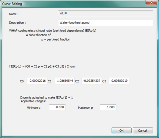
Cooling EIR Part-load Dependence curve, fEIRp(p), details and editing
Use the Edit button to view and edit the curve parameters. The Curve Editing dialog displays the formula and parameters of the curve and provides for editing of the curve parameters. You are permitted to edit the curve coefficients and the applicable ranges of the independent variables.
When editing the curve parameters, it is important that you understand the meaning of the curve and its usage in the model algorithm.
Ensure that the edited curve has reasonable ranges for the independent variables. A performance curve is valid only within its applicable ranges. If the independent variables are outside of the ranges that you set, the specified variable limits (maximum or minimum values) will be used.
Figure 3 - 62 : Edit dialog for the water-to-air heat pump cooling EIR part-load dependence curve
The cooling EIR (part-load dependence) curve f EIRp (p) is a bi-quadratic function of
p = Q/Q cap
where
p = part-load fraction
Q = cooling load
Q cap = available (full-load) cooling capacity
And:
f EIRp (p) = (C 0 + C 1 p + C 2 p 2 + C 3 p 3 ) / C norm
where
C 0 , C 1 , C 2 , and C 3 are the curve coefficients,
C norm is adjusted (by the program) to make f EIRp (1) = 1
The cooling EIR (part-load dependence) curve is evaluated at each time step during the simulation. The curve value is multiplied by the rated EIR (= 1/ COP rat , where COP rat is the rated coefficient of performance) and the EIR (temperature dependence) curve value to get the EIR of the current time step, for the specific T ewb and T ewt temperatures and the specific part load ratio at which the WAHP unit is operating:
EIR = f EIRtt (T ewb, T ewt ) f EIRp (p) / (pCOP rat )
The curve should have a value of 1.0 when the part load ratio equals 1.0 and the temperatures are at rated conditions.
A note on the applicable range of part-load ratio p:
The minimum p is used by the program as the minimum unloading ratio, where the WAHP unit capacity can no longer be reduced by normal unloading mechanism and the WAHP unit must be false loaded to meet smaller loads. A typical false loading strategy is hot-gas bypass. If this is the false loading strategy used by the WAHP unit, the minimum p is the part load ratio at which hot gas bypass starts.
The maximum p should usually be 1.0. During the simulation, a part-load ratio greater than 1.0 is a sign of WAHP units undersizing.