How ConstructDXF Works
The use of ConstructDXF can be broken down into the following basic operations:
· ModelIT is started and a new (or existing) project is opened.
· A drawing file in DXF format is read into ModelIT.
· Defaults for the room thermal and lighting data and fabric element constructions are set by means of room templates.
· ConstructDXF is then started within ModelIT.
· Extract settings (rules and tolerances) are set, together with default storey heights for the storey to be generated, and default window and door heights.
· A 3D data model for that storey is then generated (extracted).
· If required, another DXF drawing can then be loaded into ModelIT, and further storeys can be generated.
· Within the 3D model, the data for individual rooms and elements can be modified.
· The finalised 3D data model can then be used by the IES thermal and/or lighting software for calculation purposes.
· Calculated luminaires can be added to the 3D model.
Preparation of the DXF Drawing
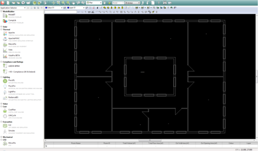
First, start ModelIT, and open a new or existing project by selecting New or Open from the File menu. Next, from the File menu, select Reference Files, and select Attach DXF File to find and attach your required DXF drawing. The DXF drawing will then be displayed in the ModelIT window.
Layers (levels) in the DXF file can be switched on or off within ModelIT. To do this, use the File menu and select Reference Files, then Active DXF Layers. Layers which contain elements which are not to form part of the building model (grids, dimensions, furnishing and fitting symbols, etc.) should be turned off.
ConstructDXF is designed to operate on DXF plan view drawings. If required, the same DXF file may be used for several storeys.
A DXF drawing in ModelIT
Setting Up Room Templates Using the Building Template Manager
ConstructDXF uses room templates, which contain defaults for both construction and non-graphical attribute data (lighting, thermal, casual gains, air exchange, etc). The available templates are shown in the drop down list in the dialogue bar at the bottom of the ModelIT window.
Templates are created and edited using the Building Template Manager utility, which is accessed via the Templates menu on the <VE> menu bar (see the Building Template Manager User Guide for further information).
Note that you do not have to use the Building Template Manager before you generate a model. If you have no attribute information, just use the ‘default’ template. Rooms that are generated will be assigned default attributes, and you can then modify the attributes of each room individually when you have the correct attribute information.
Starting ConstructDXF
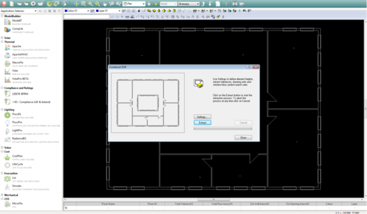
Select ConstructDXF from the Utilities menu. The ConstructDXF window will appear within the ModelIT environment.
The ConstructDXF window within ModelIT
ConstructDXF Rules
In building a 3D model from the DXF information, ConstructDXF applies a number of rules which are summarised in this section.
Basic Rules
ConstructDXF applies three basic rules to each DXF file in order to identify building perimeters, room perimeters and bordering elements including roofs, ceilings, internal floors, ground floors, external walls and internal partitions:
· Rule 1 - Each building on a site must have a closed external loop which may incorporate door symbols and window symbols (see Windows and Doors below).
· Rule 2 - All internal spaces or rooms must have a closed internal loop which may include door and window symbols (see Windows and Doors below). The internal loop may be composed of the same elements as the external loop.
· Rule 3 - All rooms must have one label located within the room perimeter.
Room Names
All rooms to be included in the model should have one label located within the space and with its origin not contained within a confining element. ConstructDXF will recognise the existence of multiple labels within one room but this will significantly increase the processing time and therefore any unnecessary text should be removed.
Note origins of text labels must not lie within the thickness of a wall.
Voids
Spaces within the perimeter of a building that represent external spaces will be recognised if the name matches the Void Label which is set under the AutoExtract Settings (see Settings).
Continuous Vertical Stacked Spaces
Any space that is continuously joined with another space above or below will be correctly identified if the name matches the Stack Label set under the AutoExtract Settings (see Settings).
Windows
Window symbols are identified using the following hierarchical rules:
1. Any element found on a drawing layer (level) specified as a Window layer in the AutoExtract Settings.
2. Any sequence of elements forming an overlaid or indented rectangle within an external wall.
3. A number of parallel lines within an external wall element. This number must be greater than or equal to the Minimum Number of Window Lines setting for the identification of a window.
Window rules also take into account the dimensions entered under the AutoExtract Settings.
See Settings for more details.
Doors
Doors may be represented using two lines at an angle of between 30 degrees and 60 degrees to each other or a 90-degree swept arc. Small line segments included within a door symbol will automatically be ignored. Doors are included within the model in the closed position. Door rules also take into account the dimensions entered under the AutoExtract Settings.
See Settings for more details.
A Quick Guide to Generating a ConstructDXF Model
Start ModelIT and create a new project by selecting ‘New’ from the File pull down menu.
Attach a DXF drawing using the Reference Files option from the File menu. Turn off all unnecessary layers in the drawing.
Start ConstructDXF. Check that the extract settings are appropriate for the current DXF file then click on the Extract button to generate the data model. The model generation progress will be displayed on a completion bar.
The process may be aborted at any stage by pressing the Cancel button.
When the extract process is complete, the generated building model data is written to a model project file with the extension *.mit. This file holds both geometric or spatial data and non-graphical attribute data.
When you close ConstructDXF, the ModelIT facilities that allow you to modify the data model are now enabled.
If required, another DXF drawing can then be loaded into ModelIT, and further storeys can be generated.
The attribute data for each room may be viewed and edited by clicking on the Query button in ModelIT. The construction and dimensions of various elements may be viewed and modified by clicking on the Query button.
Once the model has been generated and the room and room element data have been edited as required, you can then run the various IES programs by selecting the appropriate program from the Applications menu.