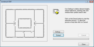
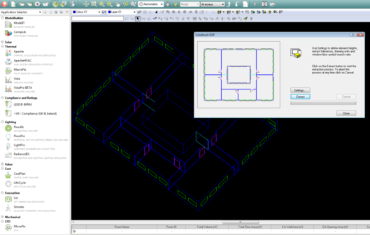
The ConstructDXF window is where extract settings are specified, and from where the model is generated.
Note that some of the facilities in ModelIT will be disabled until you have generated a 3D model.
When ConstructDXF is first started, the ConstructDXF window displays the model view which is comprised of the current DXF drawing and the 3D model (if it has been generated).
The ConstructDXF window showing the DXF drawing
Settings
Clicking on the Settings button in ConstructDXF opens the Settings dialogue box, which is split into tabbed sections.
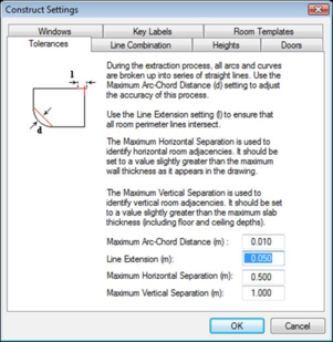
Settings - Tolerances Tab
This contains controls to set various tolerances used during the model generation process.
Settings - Tolerances tab
Max Arc-Chord Distance
ConstructDXF will convert all arcs and curves into series of straight lines or vectors. The arc-chord distance is the maximum distance between the resulting vectors and the actual line. A very small arc-chord distance will result in a very accurate representation of the arc or curve but will result in a longer processing time and conversely a large arc-chord distance will produce a less accurate model but much faster processing times. Any arc having a radius within the minimum-maximum door width range will automatically be converted to a single straight line.
Line Extension
Having extracted all drawing elements from the DXF file, ConstructDXF then converts all elements into series of lines or vectors. In order to cater for drafting inaccuracies or errors in file translation, an extension may be added to the ends of all vectors to ensure that lines that should meet do actually meet. Be careful when applying extensions not to inadvertently cause lines to be joined which should be kept separate.
Maximum Horizontal Separation
This allows you to identify horizontal room adjacencies. This value should be set to slightly greater than the maximum wall thickness as it appears in the drawing.
If the distance between one space and another space (after model extraction) is less than this value, the two spaces are deemed to be adjacent to one another, i.e. the facing elements of each space are the same connecting partition.
If the distance between the two spaces is greater than the adjacency separation distance, then the two spaces are deemed to be independent of each other, i.e. the facing elements of each space are exterior walls.
Maximum Vertical Separation
This allows you to identify vertical room adjacencies. This value should be set to slightly greater than the maximum slab thickness (including floor and ceiling depths).
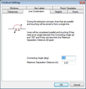
Settings - Line Combination Tab
During the model generation process, any lines or vectors which are considered to be parallel and touching will be combined into a single vector. The Line Combination tab contains the tolerancing controls for determining whether or not lines should be combined.
Settings - Line Combination tab
Connecting Angle
Two lines will be considered parallel if they meet at an angle between the Connecting Angle and 180 degrees.
Max. Separation
The maximum distance between two lines, below which the lines are considered to be touching.
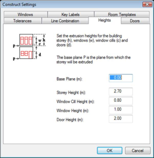
Settings - Heights Tab
This tab is used to set default heights for the automatic model generation.
Settings - Heights tab
Base Plane
The base plane is the point in the model Z (height) plane from which the storey will be extruded.
Storey Height
The storey height is defined as the distance between the finished floor level and the finished ceiling level (i.e. the useable room height).
Window Cill Height
The default window cill height is the height of the window cills from the finished floor level.
Window Height
This is the default window height above the cill height.
Door Height
This is the default height of doors above the finished floor level.
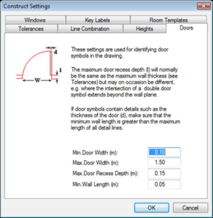
Settings - Doors Tab
This tab contains controls that are used to set tolerances for the identification of door symbols in the drawing.
Settings - Doors tab
Min. Door Width
Doors may be represented using two lines at an angle of between 30 degrees and 60 degrees to each other or a 90-degree swept arc. If the line representing the door (as opposed to the sweep) is less than the minimum door width, the symbol will not be interpreted as a door.
Max. Door Width
Doors may be represented using two lines at an angle of between 30 degrees and 60 degrees to each other or a 90-degree swept arc. If the line representing the door (as opposed to the sweep) is greater than the maximum door width, the symbol will not be interpreted as a door.
Max. Door Recess Depth
This tolerance caters for cases where the door symbol has been draughted such that the door panel line originates from one point relative to the wall (e.g. the inner surface of the wall), and where the door swing line or arc originates from another point relative to the wall (e.g. the outer surface of the wall, or within the room).
This may occur where the intersection of a double door symbol extends beyond the wall plane.
If the distance (perpendicular to the wall) between these two points is greater than the maximum door thickness, the symbol will not be interpreted as a door.
Min. Wall Length
If the length of a wall element is less than the minimum wall length, ConstructDXF will not identify this element as a wall. ConstructDXF also uses this tolerance in the identification of door elements. If door symbols contain details such as the thickness of a door, make sure that the minimum wall length is greater than the maximum length of all detail lines.
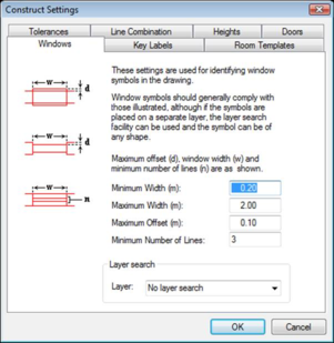
Settings - Windows Tab
This tab contains controls that are used to set tolerances for the identification of window symbols.
Window symbols are identified using the following hierarchical rules:
· Any element found on a drawing layer (level) specified in the Layer box.
· Any sequence of elements forming an overlaid or indented rectangle within an external wall.
· A number of parallel lines within an external wall element. This number must be greater than or equal to the Minimum Number of Lines setting for the identification of a window.
Settings - Windows tab
Min. Width
A window symbol will not be interpreted as a window if its width is less than the minimum window width.
Max. Width
A window symbol will not be interpreted as a window if its width is greater than the maximum window width.
Max. Offset
A window may be represented by a rectangle overlaying or indented within an external wall element. If the offset or indent of the rectangle sides from the parallel wall surfaces is greater than the maximum window offset, it will not be interpreted as a window.
Min. No of Lines
This is the minimum number of parallel lines that have to be drawn for a window element, for that element to be identified as a window.
Layer
If a drawing layer is selected for a search, ConstructDXF looks for windows on the DXF drawing layer (or level) that is selected. If you do not wish to search on other layers, select ‘No Layer Search’.
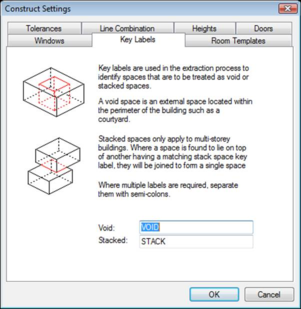
Settings - Key Labels Tab
String patterns are entered here. They are used in the extraction process to identify spaces that are to be treated as void or stacked spaces, by analysing the text in the rooms in the DXF file. Stacked spaces only apply to multi-storey models.
Settings - Key Labels tab
Void
This is used to define a search string pattern for external spaces within a building perimeter, e.g. courtyards, light-wells, etc. Any room having a name, which complies with the void space search string pattern, will be considered an external space (e.g. courtyard). The string may contain wild-card characters (* and ?). For example to include all rooms containing the string 'court', you would type in ‘*court*’. More than one key label can be defined by using a semicolon to separate the labels.
Stacked
This is used to define a search string pattern for spaces that are vertically continuous. Any room having a name, which complies with the stacked space search string pattern, will be considered a vertically stacked space (e.g. stairwell). The string may contain wild-card characters (* and ?). For example to include all rooms containing the string 'stair', you would type in ‘*stair*’. More than one key label can be defined by using a semicolon to separate the labels.
The default values set up in these Settings tabs are the result of extensive application and have been found to be appropriate for most cases. Consequently, if you are uncertain of which values to use for a drawing file, try generating a model using the default values and then modify them if necessary.
Check that the minimum/maximum door range and minimum window length and maximum window offset cover all occurrences in the drawing.
When you have entered the required data in all the above tabs, press OK to update the Settings. The Settings dialogue box will then close.
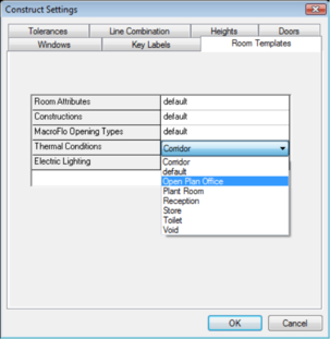
Settings – Room Templates Tab
The room templates tab lets the user select which template is to be applied to all the zones constructed from the DXF drawing. Templates allow for easy designation of common zone features and conditions when constructing a <VE> model. Only one template for each category can be assigned to all the zones during a ConstructDXF operation. More information on templates can be found in the Building Template Manager user guide.
Settings – Room Templates tab
Room Attributes Template
This section allows the user to set the percentage of floor area that is lettable or circulation.
Constructions Template
This section is where the opaque and glazed constructions are specified for templates.
MacroFlo Opening Types Template
This section is where the MacroFlo opening types are assigned to templates. The opening types available are:
• Rooflight
• External Glazing
• Internal Glazing
• Door.
Thermal Conditions Template
This section is where room thermal conditions are assigned to templates. There are four tabs for thermal conditions data (five if Building Regulations are enabled):
• Building Regs (optional)
• Heating
• Cooling
• Casual Gains
• Air Exchanges
.
Electric Lighting Template
This section allows electric lighting data to be assigned to templates used by programs within the <VE> Lighting section.
Extract
Clicking on the Extract button initiates the model generation process which is displayed on a percentage completion bar. The process may be aborted at any stage by clicking on the Cancel button.
When the Extract process is complete, you will see the generated model in both the ModelIT window and in the ConstructDXF window.
A generated model
If required, another DXF drawing can then be loaded into ModelIT, and further storeys can be generated. To do this, close ConstructDXF, then use the Reference Files option from the File menu to attach the next DXF file. Then start ConstructDXF again. Before you extract the next storey, make sure that the value of the Base Plane in the Heights tab of the Settings dialogue box is equal to or greater than the Z value of the top of the current storey.
Note that you need to close the ConstructDXF window before you can use any of the ModelIT facilities.