The Thermal storage tab within the Chilled water loop dialog provides access to editing, adding, or removing thermal storage systems. A thermal storage loop is dedicated to charging/discharging a thermal storage device. The thermal storage tab provides inputs for the following
· charge and discharge cycle parameters, including scheduling, flow rates, & design temperatures
· tank storage capacity & losses
· chillers and other similar cooling sources (adding, editing, and designating cooling equipment for building cooling on the thermal storage loop)
· heat-rejection loop (for water-cooled chillers) with cooling tower and fluid cooler options
A thermal storage loop is associate with a thermal storage chiller set comprising any number of chillers, which can include any combination of three different types:
· electric water-cooled chiller (uses editable pre-defined curves and other standard inputs)
· electric air-cooled chiller (uses editable pre-defined curves and other standard inputs)
· part-load-curve chiller (flexible generic inputs; can represent any device used to cool water via a matrix of load-dependent data for COP and associated usage of pumps, heat-rejection fans, etc., with the option of adding COP values for up to four outdoor DBT or WBT conditions)
The chiller model and chiller curve options for thermal storage chillers are modified from those used for chilled water loops so as to be appropriate for use on a loop that operates below the freezing temperature of water.
Heat rejection for water-cooled chillers is through an associated condenser water loop. Air-cooled chillers use only the design temperatures (DBT and WBT) for heat rejection. Heat rejection for the generic part-load-curve “chiller” type is described by the user via any combination of COP values, pump power, and fan power (all or any of which can be included in a composite COP) in the dialog for that type of equipment.
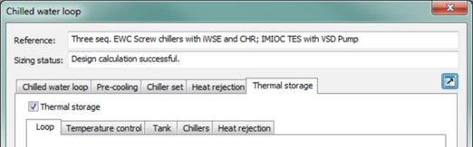
Thermal storage loops are accessed through the Chilled water loop dialog (see section 3.9.2 ) via their own tab (see Figure 3-77 ). The Thermal storage tab currently has five sub-tabs:
· Loop tab: This tab manages the properties of the thermal storage loop
· Temperature control tab: This tab defines loop fluid temperatures for different cycles
· Tank tab: This tab manages properties of the thermal storage tank
· Chillers tab: This tab manages a list of chillers (a chiller set) which may be edited with chiller dialogs
· Heat rejection tab: This tab manages information used for heat rejection. An optional condenser water loop for use by electric water-cooled chillers can be defined in this tab.
Figure 3 - 77 : Thermal storage tab of the Chilled water loop dialog with Loop sub-tab selected.
Thermal Storage dialog
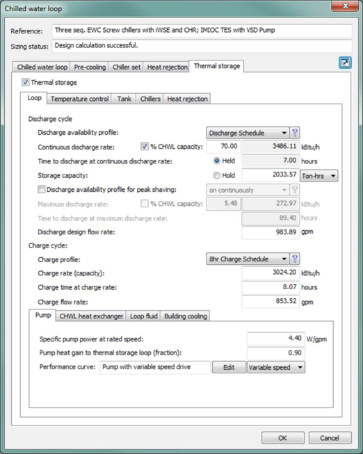
Figure 3 - 78 : Loop sub-tab of the Thermal storage tab in the Chilled water loop dialog (shown with inputs for an illustrative loop configuration)
Loop tab
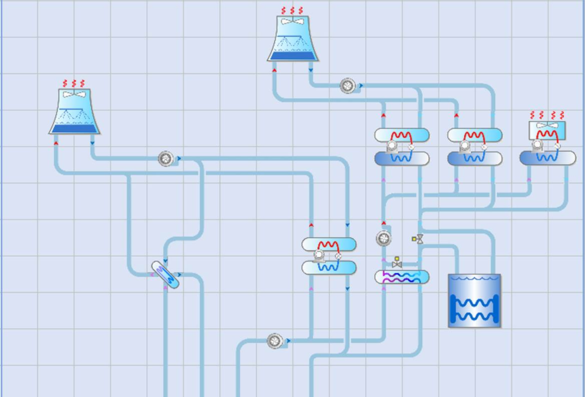
The Loop sub-tab facilitates the definition of the thermal storage discharge and charge cycles, together with the thermal storage loop pumps, heat exchanger, and fluid properties. The discharge cycle parameters determine the capacity, rate, and availability of cooling when the thermal storage system is utilized for addressing the building cooling load. The charge cycle parameters determine the capacity, rate, and availability for creating the cooling capacity utilized by the discharge cycle. Discharge and charge cycles should not overlap as the thermal storage system only operates in one mode at a time.
Three design parameters are used to set tank capacity/discharge performance:
· Total capacity,

(kWh Btu)
· Discharge rate,
 discharge
 (kW Btu/h)
· Time to discharge, ∆tdischarge (hr)
Two parameters are specified by the user and the third is derived per the following:
 discharge
 * ∆t
discharge
Discharge rate may be autosized and will be considered an input value when autosized. Users define which parameter is derived by selecting the Hold radio button and thus, toggling it to Held. Held variables are fixed while the other two variables are derived per the above equation.
Discharge availability profile
The thermal storage discharge cycle may be controlled by an on/off schedule. This schedule can be daily, weekly, or annual and is created/edited in the Apache Profiles Database. When the discharge profile is on, thermal storage discharging will occur if cooling load is placed on the thermal storage fluid to fluid heat exchanger.
Continuous discharge rate
Discharge rate may autosized either as an independent value or as a percentage of the chilled water loop capacity. The autosized percentage can be greater than 100%.
Time to discharge at continuous discharge rate
The time required to discharge stored thermal energy is calculated based on the discharge rate defined above and used to derive the storage capacity value below. The time to discharge can be held constant as per section 3.10.2 .
Storage capacity
The storage capacity of the thermal storage tank can be defined in units of Ton-hours or kBtu. When the Time to discharge at continuous discharge rate is held constant, the storage capacity is used to derive the Continuous discharge rate. The storage capacity value is used for simulation and not merely reported for user reference.
The storage capacity is also editable on the Tank sub-tab. When the storage capacity on the Loop sub-tab is Held, the ability to edit the value on the Tank sub-tab is removed.
Discharge availability profile for peak shaving
Thermal storage discharging may occur specifically for reducing the peak cooling load on the chilled water loop. If the availability profile is engaged by ticking the box, this peak shaving cycle may be controlled by an on/off schedule.
Maximum discharge rate
When thermal storage discharging is available for peak shaving, the maximum discharge rate may be defined as a percentage of the chilled water loop capacity or as an explicit value. This rate often exceeds the Continuous discharge rate but is not required to. The maximum discharge rate influences the chilled water loop load allocation during simulation.
Time to discharge at maximum discharge rate
The time required to discharge the thermal storage capacity at the maximum discharge rate is derived from the storage capacity and the maximum discharge rate. This value is editable in the range of 0 to 100 hours and will update the maximum discharge rate when modified.
Discharge design flow rate
The rate of fluid flow during the discharge cycle of the thermal storage loop is a function of the fluid properties and the discharge design delta temperature.
Charge profile
The thermal storage charge cycle may be controlled by an on/off schedule. This schedule can be daily, weekly, or annual and is created/edited in the Apache Profiles Database. When the charge profile is on, thermal storage charging will occur if the ice tank is below full charge. This profile may also control the chilled water loop primary supply water temperature setpoints as necessary for thermal storage charging.
Charge rate (capacity)
The capacity of the charging cycle is defined by the rate the thermal storage tank can charge. When specified, the charge rate will be used to derive the Charge time at charge rate using the thermal storage capacity.
Charge time at charge rate
The time required to charge the thermal storage tank is displayed based upon the storage capacity and charge rate. When this value is edited, the Charge rate will update based upon the thermal storage capacity.
Charge flow rate
The rate of fluid flow during the charge cycle of the thermal storage loop is a function of the fluid properties and the charge design delta temperature.
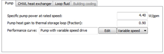
Figure 3 - 79 : Pump sub-tab of the Loop sub-tab of the Thermal storage tab in the Chilled water loop dialog, shown with a variable speed pump selected
Pump
Enter the thermal storage loop specific pump power at rated speed, expressed in W/(l/s) in SI units (or W/gpm in IP units).
Enter the thermal storage loop water pump heat gain to thermal storage loop, which is the fraction of the motor power that ends up in the thermal storage fluid. Its value is multiplied by the thermal storage pump power to get the thermal storage pump heat gain.
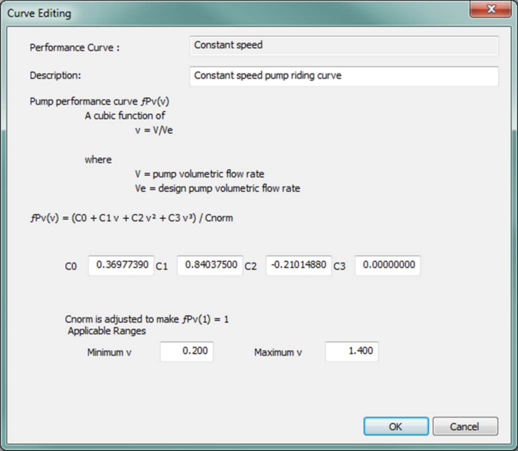
Constant speed and variable speed options are provided for the pump performance curve and can be selected using the drop down menu. Use the edit button to edit the curve parameters if needed. The Edit button opens a dialog displaying the formula and parameters of the curve. Curve coefficients and applicable ranges of the independent variables are editable.
When editing curve parameters, it is important to understand the meaning of the curve and its usage in the model algorithm. It is also important that the edited curve has reasonable applicable ranges for the independent variables. A performance curve is valid only within its applicable ranges. If the independent variables are out of the set applicable ranges, the variable limits (maximum or minimum) specified in the input will be applied.
The secondary circuit chilled water pump power curve f Pv (v) is a cubic function of
v = V/V e
where
V = pump volumetric flow rate.
V e = design pump volumetric flow rate.
And:
f Pv (v) = (C 0 + C 1 v + C 2 v 2 + C 3 v 3 ) / C norm
where
C 0 , C 1 , C 2 and C 3 are the curve coefficients
C norm is adjusted (by the program) to make f Pv (1) = 1
Figure 3 - 80 : Edit dialog for the thermal storage loop pump power curve (values for constant-speed pump are shown)
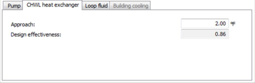
Figure 3 - 81 : Chilled water loop heat exchanger sub-tab of the Loop sub-tab of the Thermal storage tab in the Chilled water loop dialog
CHWL heat exchanger
The approach parameter sets the performance of the thermal storage discharge cycle at the design conditions in terms of the temperature difference between the leaving water on the load side and the enter water on the source side. For example, if the source water from the thermal storage loop is 46°F and the heat exchanger modeled is capable of cooling the chilled water supply, at design conditions with respect to temperature and flow rate, down to 44°F, the approach would be 2°F.
Design effectiveness is a non-editable derived parameter representing the performance of the chilled water loop heat exchanger at design conditions in terms of an effectiveness value between 0.0 and 1.0, with 1.0 representing a perfect heat exchanger. The design effectiveness value is derived from the user input for approach. During simulation, the heat exchanger model modulates the effectiveness to account for off-design conditions, including non-design water flow rates and variations in the delta-T across the heat exchanger.
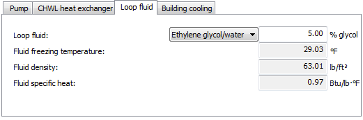
Figure 3 - 82 : Loop fluid sub-tab of the Loop sub-tab of the Thermal storage tab in the Chilled water loop dialog
Loop fluid
The thermal storage loop fluid is a glycol/water mixture to allow for subfreezing temperatures. The fluids available include ethylene glycol, propylene glycol, or water with no glycol in the mixture. The user may specify the glycol/water mixture ratio. The fluid freezing temperature, density, and specific heat are derived from this mixture ratio.
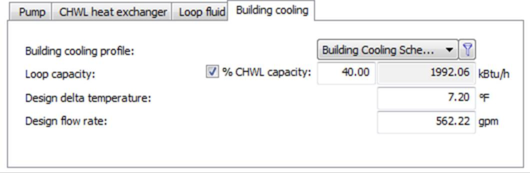
Figure 3 - 83 : Building cooling sub-tab of the Loop sub-tab of the Thermal storage tab in the Chilled water loop dialog
Building cooling
The Building cooling sub-tab will be disabled if no thermal storage chiller is designated for building cooling. Assuming at least one thermal storage chiller is available for building cooling, the building cooling functionality may be controlled by an on/off schedule. This schedule can be daily, weekly, or annual and is created/edited in the Apache Profiles Database. When the building cooling profile is on, the chillers available for building cooling will address the chilled water loop load if cooling load is placed on the thermal storage fluid to fluid heat exchanger. When thermal storage chillers are in building cooling mode, the tank is fully bypassed.
The capacity of the thermal storage chillers can be calculated as a percentage of the chilled water loop capacity or by entering an explicit loop capacity. The capacity of the thermal storage chillers will then be the maximum of the sizing for the design charge rate and the sizing for building cooling.
Design delta temperature is reported from the Temperature control sub-tab but may be edited. When edited by the user, the value on the Temperature control sub-tab is updated to match.
The rate of fluid flow during building cooling mode is a function of the fluid properties and the discharge design delta temperature.
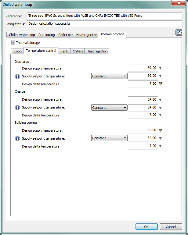
Temperature control tab
The Temperature control sub-tab defines the design conditions for the discharge cycle, charge cycle, and, when engaged, the building cooling mode of the thermal storage loop. To activate the building cooling temperatures, a thermal storage chiller on the Chillers sub-tab of the Thermal Storage tab must be selected as Use for building cooling.
Figure 3 - 84 : Temperature control sub-tab of the Thermal storage tab in the Chilled water loop dialog
Discharge Design supply temperature
This is the design discharge supply water temperature leaving the thermal storage tank.
Discharge Supply setpoint temperature
This is the discharge-mode temperature entering the supply side of the thermal storage loop fluid-fluid heat exchanger that is connected to the chilled water loop. This temperature setpoint may be constant, defined by an absolute profile, or set to maintain a constant approach.
It is suggested that this temperature setpoint be lower than the chilled water loop supply water temperature setpoint to maintain a good approach on the heat exchanger.
Discharge Design delta temperature
Discharge design delta temperature is calculated from the discharge design flow rate on the Loop sub-tab as a function of the specific heat and density values derived from the Loop fluid sub-tab. The temperature may be edited and will update the discharge design flow rate when changed.
Charge Design supply temperature
The design supply temperature for the charge cycle is used as the design condition for the chilled water supply temperature, Tletdes, in the thermal storage chillers dialog.
Charge Supply setpoint temperature
This is the charging-mode temperature entering the thermal storage tank. This temperature setpoint may be constant, defined by an absolute profile, or set to maintain a constant approach.
Charge Design delta temperature
Charge design delta temperature is calculated from the charge design flow rate on the Loop sub-tab as a function of the specific heat and density values derived from the Loop fluid sub-tab. The temperature may be edited and will update the charge design flow rate when changed.
Building cooling Design supply temperature
The design supply temperature for building cooling mode is used as the design condition for the chilled water supply temperature, Tletdes, in the thermal storage chillers dialog when this temperature is lower than the Charge Design supply temperature.
Building cooling Supply setpoint temperature
This is the building-cooling-mode temperature entering the supply side of the thermal storage fluid-fluid heat exchanger that is connected to the chilled water loop. This temperature setpoint may be constant, defined by an absolute profile, or set to maintain a constant approach.
Building cooling Design delta temperature
Building cooling design delta temperature is calculated from the Building cooling design flow rate on the Building cooling sub-tab as a function of the specific heat and density values derived from the Loop fluid sub-tab. The temperature may be edited and will update the Building cooling design flow rate when changed.
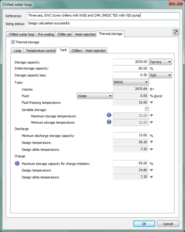
Tank tab
Figure 3 - 85 : Tank sub-tab of the Thermal storage tab in the Chilled water loop dialog
Storage capacity
Tank Storage capacity and thermal Storage capacity from the Loop sub-tab are copies of each other, both defining the storage capacity of the tank. Editing one value on one tab automatically changes the value of the other. When Thermal Storage capacity is Held on the Loop sub-tab it is inactive/non-editable on the Tank sub-tab.
Initial storage capacity
This is the capacity of the tank at the start of simulation, before any charging, discharging, or capacity loss over time. As simulations start at midnight, the initial capacity of the tank is likely close to fully charged.
Storage capacity loss
The rate of loss of storage capacity over time may be defined in units of percent capacity per hour, Ton-hrs per hour, or kBtu per hour.
Tank Type
Two tank types are available on the thermal storage loop: an internal-melt ice-on-coil system (IMIOC) and a chilled fluid storage tank. A chilled fluid tank selection results in a sensible storage only system. When IMIOC is selected, the default system is latent storage only, but a Sensible storage check box is provided for when both latent and sensible storage are desired.
Volume
Derivation of the tank volume depends upon the type of tank and/or sensible storage option. For an IMIOC tank, the volume is a function of the storage capacity. For chilled fluid storage and IMIOC tanks with sensible storage, the volume is a function of storage capacity, tank fluid properties, and the difference between the maximum storage temperature and the fluid freezing temperature.
Fluid
The tank fluid is a glycol/water mixture to allow for subfreezing temperatures. The fluids available include ethylene glycol, propylene glycol, or water with no glycol in the mixture. The user may specify the glycol/water mixture ratio. The fluid freezing temperature is derived from this mixture ratio.
Fluid freezing temperature
The fluid freezing temperature is derived from the amount of glycol specified in the fluid.
Sensible storage
The sensible storage check box indicates whether sensible storage occurs in the tank. When a chilled fluid tank is selected, the box is checked by default and cannot be unchecked. When an IMIOC tank is chosen, the box is unchecked by default – indicating latent storage only – but can be checked to include sensible storage with the IMIOC system.
The maximum and minimum storage temperatures are disabled when Sensible storage is not selected.
Maximum storage temperature
When the tank type is IMIOC with Sensible storage, the maximum storage termpature must be greater than the fluid freezing temperature. When the tank type is Chilled fluid, the maximum storage temperature must be greater than both the fluid freezing temperature and the minimum storage temperature.
Minimum storage temperature
When the tank type is Chilled fluid, the minimum storage temperature must be greater than the fluid freezing temperature.
Minimum discharge storage capacity
The minimum discharge storage capacity is the capacity of the tank at which discharging stops because the remaining capacity is unrecoverable. If the tank capacity is below (or equal to) this value at the beginning of the discharge cycle, no discharge is allowed. Tank capacity can be less than this minimum value due to storage losses.
Discharge Design temperature
The discharge design temperature from the Temperature control sub-tab is reported on the Tank sub-tab for reference.
Discharge Design delta temperature
The discharge design delta temperature from the Temperature control sub-tab is reported on the Tank sub-tab for reference.
Maximum storage capacity for charge initiation
If the tank has been fully charged, maximum storage capacity for charge initiation will prevent charge cycling by not re-initiating charging until storage capacity falls below this value. This will prevent charge cycling due to small non-discharge losses.
Charge Design temperature
The charge design temperature from the Temperature control sub-tab is reported on the Tank sub-tab for reference.
Charge Design delta temperature
The charge design delta temperature from the Temperature control sub-tab is reported on the Tank sub-tab for reference.
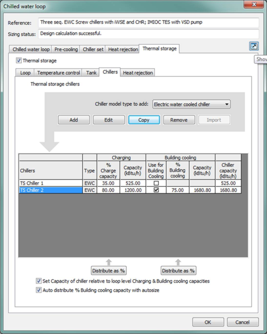
Chillers tab
Thermal storage chillers are designated on the thermal storage Chillers sub-tab, similar to the Chiller set dialog in the Chilled water loop dialog. A Use for Building Cooling selection box allows the user to designate a thermal storage chiller to also serve the building cooling load. The thermal storage chillers can operate with a subfreezing glycol/water mixture. Special chiller performance curve sets have been developed from existing VE chiller performance curves for these chillers.
Chillers can be added, edited, copied and removed from the existing chiller list using the corresponding buttons. The cells containing chiller names in the Chiller list column provide access to editing individual chillers.
Figure 3 - 86 : Thermal storage chiller set dialog shown with two chillers, one of which is designated for building cooling
Chiller Model Type to Add
Selection made in this combo list determines the model type of the chiller to be added by clicking the chiller Add button. Currently three model types are available: part load curve chiller, electric water-cooled chiller or electric air-cooled chiller.
The chiller set can include any number of chillers or similar cooling sources defined using one of three models, and the set can include any combination of the three different model types:
· electric water-cooled chiller (uses editable pre-defined curves and other standard inputs)
· electric air-cooled chiller (uses editable pre-defined curves and other standard inputs)
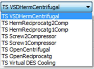
· part-load-curve chiller (flexible generic inputs; can represent any device used to cool water via a matrix of load-dependent data for COP and associated usage of pumps, heat-rejection fans, etc., with the option of adding COP values for up to four outdoor DBT or WBT conditions)
The chiller model and chiller curve options for thermal storage chillers are modified from those used for chilled water loops so as to be appropriate for use on a loop that operates below the freezing temperature of water.
Figure 3 - 87 : List of pre-defined performance curve sets specific to thermal storage chillers
Chiller List
The Chillers column lists the chillers and similar cooling sources in the chiller set for the current thermal storage loop. To open the edit dialog for that chiller, double-click a chiller name on the list or select a chiller and click the Edit button. This action will open the same edit dialog as for chilled water loop chillers (see section 3.12 for water-cooled and section 3.13 for air-cooled chillers).
Chiller Type
The chiller Type column lists the types of the chillers defined for the thermal storage loop. The chiller types are determined automatically by the program depending on the chiller model type selection when the chillers are added.
Currently there are three chiller model types available: part load curve chiller, electric water-cooled chiller, and electric air-cooled chiller.
Charging Capacity
The capacity of each chiller on the thermal storage loop can be sized as either a percentage of total charge capacity or by an explicit capacity value. Editing one value will derive the non-edited value using the current value of Charge rate defined on the Loop sub-tab. The percentage charge capacity column does not need to sum to 100% and the range for percentage capacity for individual chillers is 0% - 200%, allowing for a single thermal storage chiller to be oversized relative to one thermal storage mode so as to have adequate capacity in off-design conditions during another thermal storage mode.
A Distribute as % button is active whenever the sum of the % Charge capacity column is not equal to 100%. Selecting this button will normalize all % Charge capacity values.
An option to set the capacity of the chiller(s) relative to the loop level Charging & Building cooling capacities is provided by a tick box below the chiller set table. When ticked (as is the default), % Charge capacity of the chiller will not change as the thermal storage loop capacity changes. When unticked, Charging capacity values will not change.
Building Cooling
A Use for Building Cooling selection box is available for thermal storage chillers and allows a thermal storage chiller to be designated to also serve building cooling loads. For thermal storage chillers designated for Building cooling, the chiller autosize capacity will be calculated referencing the Building cooling sub-tab % of CHWL capacity value. The actual capacity for thermal storage chillers designated for Building cooling will then be the max of the Charge rate and Building cooling autosize values.
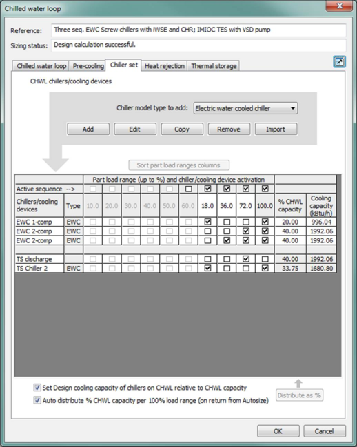
Any thermal storage chiller(s) designated for Building cooling within the thermal storage chiller set dialog will appear in the chilled water loop Chiller set table. The thermal storage discharge as well as any thermal storage chillers designated for building cooling may be sequenced with other building cooling chillers, if any exist (see section 0 ). Thermal storage chillers cannot be active in the same part load range as thermal storage discharge.
Figure 3 - 88 : Chilled water loop Chiller set dialog shown with thermal storage discharge and thermal storage chiller available for building cooling
An option to Set Capacity of the chiller relative to loop level Charging & Building cooling capacities is provided by a tick box below the chiller set table. When ticked (as is the default), % Building cooling capacity of the chiller will not change as the thermal storage loop capacity changes. When unticked, capacity values will not change as the % Building cooling is changed.
An option to Auto distribute % Building cooling capacity with autosize is provided by a tick box below the chiller set table. This option normalizes the % Building cooling values following a System Loads/Sizing calculation when the box is ticked (as is the default). When the box is unticked, % Building cooling capacity values will not change.
Chiller Capacity
The capacity for thermal storage chillers is the larger of the capacities sized for the thermal storage charging cycle and building cooling mode. When a thermal storage chiller is not designated for use in meeting the building cooling load, the chiller capacity is simply the charging capacity.
Heat rejection tab
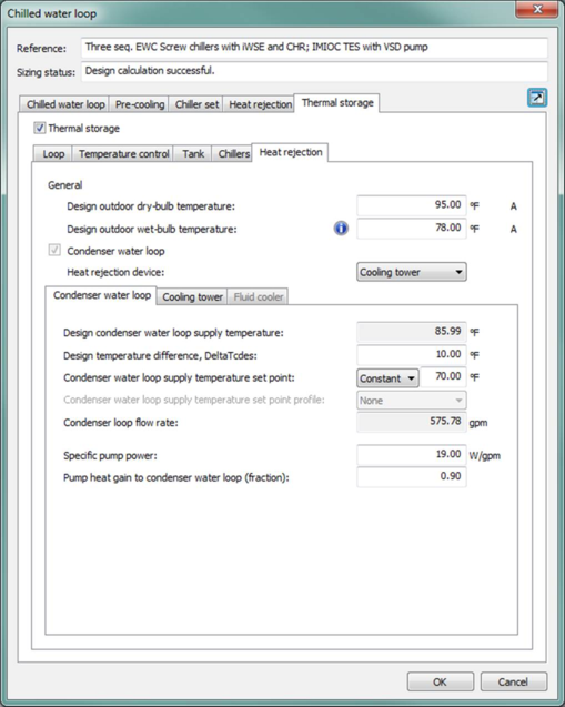
The Heat rejection sub-tab in the Thermal storage tab ( Figure 3-89 ) facilitates the definition of the design outdoor dry-bulb and wet-bulb temperatures for heat rejection and for setting the parameters of a condenser water loop. The design conditions for heat rejection are used for all electric air-cooled and water-cooled chiller models and associated cooling towers. The condenser water loop in this tab functions for all water-cooled chillers in the attached thermal storage chiller set and includes condenser water temperatures, a cooling tower or fluid cooler, and a condenser water pump. There are options for wet and dry fluid coolers (closed-circuit towers) as well as the standard open cooling tower model.
Condenser water loop flow rate is calculated from heat rejection load and condenser water temperature range at the design condition and the condenser water pump speed and flow rate are constant whenever the thermal storage chiller(s) operates. The heat rejection device (cooling tower or fluid cooler) is automatically sized for the heat rejection load at the design condition. The fan in the heat rejection device then modulates (speed if two-speed or variables-speed, otherwise on/off) in an attempt to maintain the set condenser-water loop design temperature.
If the outdoor conditions exceed the design condition and the heat-rejection device is fully loaded, including any oversizing factor applied when sizing the associated chiller(s), the return water from the tower back to the condenser will be warmer than the design condition and the chiller model will account for this in terms of both chiller capacity and energy consumption.
If the cooling tower uses a single- or two-speed fan, results for energy consumption may still appear to vary with time, as an on/off cycling ratio will be applied to the fan power for the fan speed that is in use.
Figure 3 - 89 : Heat rejection sub-tab in the Thermal storage tab of the Chilled water loop dialog with the heat rejection device set to Cooling tower.
Design Outdoor Dry-bulb Temperature
Enter the design outdoor dry-bulb temperature. This parameter is autosizable. When this parameter is autosized, its value in the field and its autosizing label ‘A’ become green.
Design Outdoor Wet-bulb Temperature
Enter the design outdoor wet-bulb temperature for the cooling tower. This parameter is autosizable. When this parameter is autosized, its value in the field and its autosizing label ‘A’ become green.
Design outdoor wet-bulb temperature has to be lower than design outdoor dry-bulb temperature.
Condenser Water Loop
When this checkbox is ticked, all of the parameters for the condenser water loop become active. There must be at least one Electric Water-cooled (EWC) chiller defined for the chilled water loop.
Heat rejection device
Select from the available options for heat rejection devices. Presently, these include an open cooling tower model or a closed-circuit fluid cooler. The open cooling tower model here is based on the Merkel theory, which is same as that used for the Dedicated waterside economizer component (see that section of the User Guide for details). The fluid cooler can be either wet, dry, or switch from wet to dry operation when outdoor temperature drops below a set threshold.
The fields and their labels visible when the Cooling tower option is selected are described immediately below. Changing the selection to Fluid cooler replaces these input fields with a set specific to the Fluid cooler parameters (described following the cooling tower inputs).
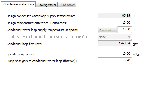
Figure 3 - 90 : Condenser water loop sub-tab in the Heat rejection sub-tab in the Thermal storage tab of the Chilled water loop dialog
Design Condenser Water Loop Supply Temperature
Enter the design condenser entering water temperature. This design value should not be confused with the set point value below. The design value is the entering condenser water temperature at the design condition.
Design Temperature Difference, DeltaTcdes
Enter the design condenser water temperature difference ∆T cdes (the difference between the condenser water leaving and entering temperatures at the design condition).
Condenser Water Loop Supply Temperature Set Point
Entering condenser water temperature set point can be constant or set according to an absolute profile. The setpoint is typically lower than the design value at which capacity is determined.
When the condenser water temperature set point is fixed, the cooling tower or fluid cooler serving the condenser is controlled in an attempt to maintain a constant condenser water supply temperature, as limited by tower/cooler performance at off-design operating conditions.
The absolute profile option allows the flexibility of using other control strategies for the cooling tower or fluid cooler supply temperature.
Condenser Loop Flow Rate
The condenser loop flow rate for the thermal storage loop is derived from the heat rejection load and condenser water temperature range at the design condition and reported here.
Condenser Water Specific Pump Power
Enter the condenser water specific pump power at rated speed, expressed in W/(l/s) in SI units (or W/gpm in IP units).
Condenser water pump power will be calculated on the basis of constant flow (whenever the chiller operates). The model will be based on a specific pump power parameter, with a default value of 19 W/gpm as specified in ASHRAE 90.1 G3.1.3.11.
The condenser water loop flow rate will be calculated from values of condenser water heat rejection load and condenser water temperature range through the condenser at the design condition.
Condenser Water Pump Heat Gain to Condenser Water Loop (fraction)
Enter the condenser water pump heat gain to the condenser water loop, which is the fraction of the pump motor power that ends up in the condenser water. Its value is multiplied by the condenser water pump power to get the condenser water pump heat gain, which is added to the heat rejection load of the cooling tower. (Condenser water pump is assumed to be on the supply side of the cooling tower.)
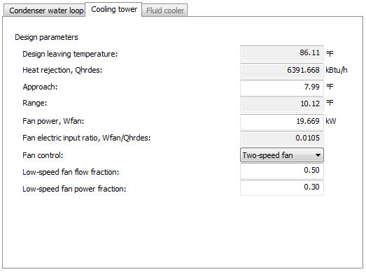
Figure 3 - 91 : Cooling tower sub-tab in the Heat rejection sub-tab in the Thermal storage tab of the Chilled water loop dialog
Cooling Tower Design Leaving Temperature
This is the design leaving water temperature of the cooling tower, also the design supply water temperature to the condenser.
Cooling Tower Design Heat Rejection, Qhrdes
This is the heat rejection load on the cooling tower at design condition. The design heat rejection load of the cooling tower is automatically derived by the program using the provided thermal storage loop design data and condenser water pump data, and does not need to be specified.
Cooling Tower Design Approach
This is the difference between the cooling tower leaving water temperature and the outdoor wet-bulb temperature at the design condition.
Cooling Tower Design Range
This is the difference between the cooling tower entering water temperature and the cooling tower leaving water temperature at the design condition. The design range of the cooling tower is derived by the program using the provided condenser water loop design temperature difference and condenser water pump data, and does not need to be specified.
Cooling Tower Fan Power, Wfan
Enter the power consumption of the cooling tower fan when running at full speed.
Cooling Tower Fan Electric Input Ratio, Wfan/Qhrdes
This is the ratio between the design fan power consumption and the design heat rejection load of the cooling tower. It is automatically derived by the program using the provided cooling tower fan power and the derived cooling tower design heat rejection load, and does not need to be specified.
Cooling Tower Fan control
Select the fan control type of the cooling tower. Three types of fan control are available
· One-speed fan
· Two-speed fan
· VSD fan
When Two-speed fan is selected, you also need to specify two more parameters (see below): Low-speed fan flow fraction and Low-speed fan power fraction.
Cooling Tower Low-speed Fan Flow Fraction
Enter the fraction of the design flow that the cooling tower fan delivers when running at low speed. This parameter only needs to be specified when Fan control type is selected as Two-speed fan.
Cooling Tower Low-speed Fan Power Fraction
Enter the power consumed by the cooling tower fan when running at low speed, expressed as a fraction of the cooling tower design fan power. This parameter needs only to be specified when Fan control type is selected as Two-speed fan. Generally, the low-speed power fraction will be a lesser value than the low-speed flow fraction. For example, if the low-speed flow fraction were 0.50, the low-speed power fraction would typically (depending on fan curves, motor performance, etc.) be on the order of 0.30.
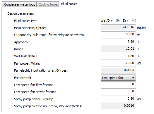
Figure 3 - 92 : Fluid cooler sub-tab in the Heat rejection sub-tab in the Thermal storage tab of the Chilled water loop dialog
Fluid Cooler Type
There are two types of fluid coolers, categorized by the wetting conditions on the surface of the coil.
A dry fluid cooler is one where the coil is permanently dry—i.e., evaporative cooling is not included. This type of cooler tends to be used in areas where there are restrictions on the availability of water or where ambient conditions are particularly well suited to a dry cooler.
A wet/dry fluid cooler is one where the coil is sprayed with water to provide indirect evaporative cooling. To prevent freezing of water on the coil and/or to make the most of cool conditions, the spray pump can be switched off at low outdoor temperatures. Under these conditions the cooler operates with a dry coil.
This radio button group allows the type of fluid cooler to be selected.
Fluid Cooler Design Heat Rejection, Qhrdes
This is the heat rejection load on the fluid cooler at design condition. The design heat rejection load of the fluid cooler is automatically derived by the program using the provided thermal storage loop design data and condenser water pump data, and does not need to be specified.
Fluid Cooler Outdoor Temperature Wet/Dry Mode Switch
When a wet/dry fluid cooler has been selected this value is used to define the temperature at which the mode of the fluid cooler changes. When the outdoor dry-bulb temperature falls below the value specified, the fluid cooler will run in dry mode, the spray pump is turned off and the coil will be dry. When the outdoor dry-bulb temperature is above the value set, the spray pump will be in operation and the coil will be wet (evaporatively cooled).
Fluid Cooler Design Approach
When the fluid cooler is operating in wet/dry mode, this is the difference between the fluid cooler leaving water temperature and the outdoor wet-bulb temperature at the design condition. In dry mode, this value is the difference between the leaving water temperature and the outdoor dry-bulb temperature at the design condition.
Fluid Cooler Design Range
This is the difference between the fluid cooler entering water temperature and the fluid cooler leaving water temperature at the design condition. The design range of the fluid cooler is automatically derived by the program using the provided thermal storage loop design data and condenser water pump data. It does not need to be specified.
Fluid Cooler ∆T
For the fluid cooler in wet/dry mode, this is the difference between the fluid cooler exiting wet-bulb air temperature and entering wet-bulb air temperature. In dry mode this is the difference between the exiting dry-bulb air temperature and the entering dry-bulb air temperature.
Fluid Cooler Fan Power, Wfan
The power consumption of the fluid cooler fan when running at full speed.
Fluid Cooler Fan Electric Input Ratio, Wfan/Qhrdes
This is the ratio between the design fan power consumption and the design heat rejection load of the fluid cooler. It is automatically derived by the program using the provided fluid cooler fan power and the derived fluid cooler design heat rejection load. It does not need to be specified.
Fluid Cooler Fan control
Select the fan control type of the cooling tower. Three types of fan control are available
· One-speed fan
· Two-speed fan
· VSD fan
When Two-speed fan is selected, you also need to specify two more parameters (see below): Low-speed fan flow fraction and Low-speed fan power fraction.
Fluid Cooler Low-speed Fan Flow Fraction
Enter the fraction of the design flow that the cooling tower fan delivers when running at low speed. This parameter only needs to be specified when Fan control type is selected as Two-speed fan.
Fluid Cooler Low-speed Fan Power Fraction
Enter the power consumed by the cooling tower fan when running at low speed, expressed as a fraction of the cooling tower design fan power. This parameter needs only to be specified when Fan control type is selected as Two-speed fan. Generally, the low-speed power fraction will be a lesser value than the low-speed flow fraction. For example, if the low-speed flow fraction were 0.50, the low-speed power fraction would typically (depending on fan curves, motor performance, etc.) be on the order of 0.30.
Fluid Cooler Spray Power, Wpump
Enter the power consumption of the fluid cooler spray pump. This input needs only to be specified for a wet/dry fluid cooler.
Fluid Cooler Spray Pump Electric Input Ratio, Wpump/Qhrdes
This is the ratio between the fluid cooler pump power consumption and the design heat rejection load of the fluid cooler. It is automatically derived by the program using the provided fluid cooler spray pump power and the derived fluid cooler design heat rejection load. It does not need to be specified.