Currently there are three chiller models implemented in ApacheHVAC: a part load curve chiller, an electric water-cooled chiller, and an electric air-cooled chiller. All three are accessed through the Chiller set tab of an associated chilled water loop. When adding chillers to the set, the chiller model type is determined by the ‘Chiller model type to add’ selection in the Chiller set tab of the Chilled water loop dialog.
The set can include any combination of the three types.
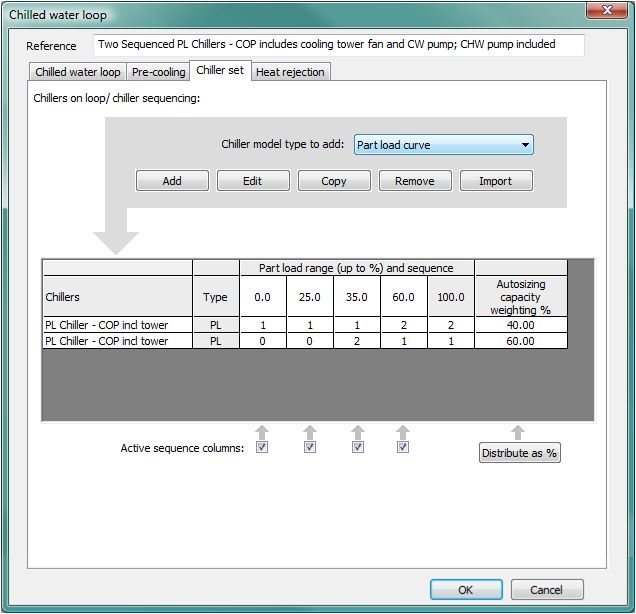
Figure 3 - 93 : Chiller set tab of Chiller water loop dialog shown with two sequenced Part-load curve chiller models and current type to add set to part load curve.
Part load curve chiller definition
The part-load-curve chiller model uses a matrix of generic inputs that can represent a very broad range of possible water cooling equipment. It comprises a matrix of load-dependent data for COP and associated usage of pumps, heat-rejection fans, etc., with the option of adding COP values for up to four ranges of outdoor DBT or WBT conditions. It also can be used to model a heat-driven Absorption chiller.
The input parameters for the Part load curve chiller model are described in this section. The electric water-cooled and air-cooled chiller models are described in sections 2.6 and 2.7, respectively.
The part load curve chiller model is similar to the analogous heat source model, but with the addition of outdoor-temperature-dependent COPs and greater detail in the description of energy use for associated pumps, fans, and so forth. In addition, basic modeling of condenser heat recovery (CHR) via double-bundle condensers or similar has been provided by allowing a portion of the heat rejected from the chiller to be made available for use on a designated heat source circuit.
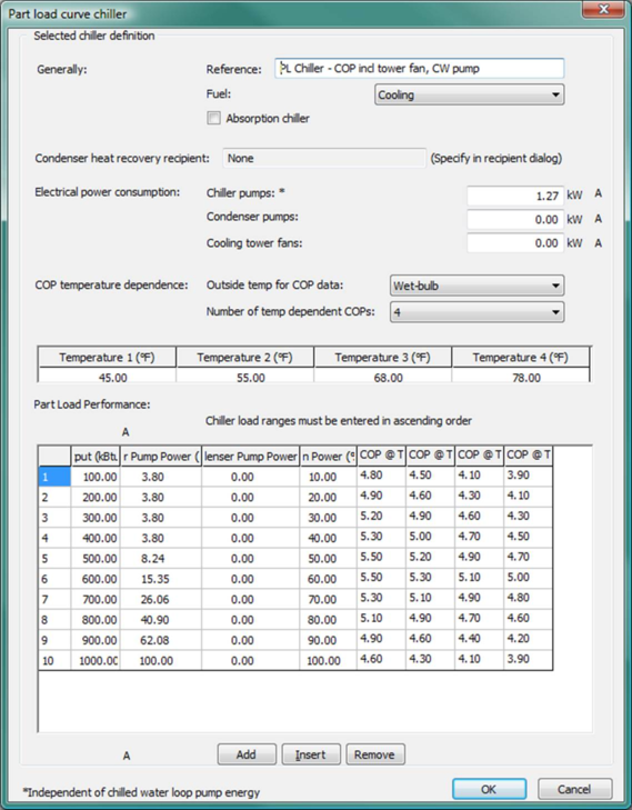
Figure 3 - 94 : Part load curve chiller editing dialog showing an illustrative example for which the cooling tower fan and condenser-water pump power are embedded in the COP values for each range of load and outdoor wet-bulb temperature and condenser heat recovery is also used.
Important note: All pump and/or fan power entered in the part load curve chiller dialog is independent of the loop pump and cooling tower energy calculated according to parameters set in the associated chilled water loop dialog—i.e., pump power and heat-rejection fan power entered in the part load curve chiller dialog is in addition to that calculated based on similar parameters in the chilled water loop dialog.
Reference
Enter a description of the component. It is for your use when selecting, organizing, and referencing any component or controllers within other component and controller dialogs and in the component browser tree. These references can be valuable in organizing and navigating the system and when the system model is later re-used on another project or passed on to another modeler. Reference names should thus be informative with respect to differentiating similar equipment, components, and controllers.
Fuel
The energy source used by the chiller compressor. For the electric chillers, this should be either the more generic ‘Electricity’ source or ‘Cooling,’ which is an electrical end-use designation that is mapped to “Cooling electricity” in the reports for the ASHRAE 90.1 Performance Rating Method (see section 8: Pre-Defined Prototype HVAC Systems and the separate user guide for the PRM Navigator). When the ‘Absorption Chiller?’ box is ticked, the ‘Fuel’ selection will be replaced with a ‘Heat source’ selection.
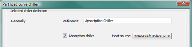
Figure 3 - 95 : Part load curve chiller editing dialog showing tick box for absorption chiller and associated selection of a driving heat source in place of the typical fuel code for electricity or energy end use.
Absorption chiller
The part load curve chiller can be used to model an absorption chiller. To enable this option, tick the Absorption chiller checkbox. The Condenser heat recovery recipient field (see below) is then removed and the Fuel selection is replaced with the absorption chiller Heat source selection. The required energy input to the absorption chiller will be passed as a load to the designated heat source.
Heat source
When the Absorption chiller checkbox is ticked, the Fuel selection is replaced with the absorption chiller Heat source selection. Select the heat source for the absorption chiller from the drop-down list of all hot-water loops and generic heat sources defined in the currently open ApacheHVAC system file. The required energy input to the absorption chiller will be passed as a load to the designated heat source.
Condenser Heat Recovery
All heat recovery data are now displayed, edited, and stored on the recipient side. The heat recovery recipient is displayed here on the source side for user’s information only. Please see sections 2.3.3, 2.4.6, and 2.8.10 for details of specifying and editing heat recovery parameters for the possible heat recovery recipients, which currently include: generic heat sources, hot water loops, or heat transfer loops.
Condenser Heat Recovery Recipient
The condenser heat recovery recipient (in the Heat recovery sub-tab) is the heat source loop that receives the heat recovered from the chiller condenser. At present, heat recovery recipient can be a generic heat source, a hot water loop, or a heat transfer loop.
If one heat source loop is specified to be the recipient of condenser heat recovery from multiple chillers, the heat recovered from those chillers will be accumulated for this heat source loop.
This field is un-editable. If the part load curve chiller has been specified as one of the heat recovery source of a heat recovery recipient, this field passively displays the name of the linked heat recovery recipient. If the part load curve chiller has not been specified as one of the heat recovery source of any heat recovery recipient, this field displays <None>.
If this field is <None>, i.e., the part load curve chiller has not been specified as one of the heat recovery source of any heat recovery recipient, the ‘Absorption chiller?’ checkbox (see above) will be enabled. Otherwise, the ‘Absorption chiller?’ checkbox is hidden.
This field is hidden when the ‘Absorption Chiller?’ checkbox is ticked. Condenser heat recovery is not available when modeling an absorption chiller. A part load curve chiller with its ‘Absorption chiller?’ checkbox ticked will not be available in the heat recovery source combo list of any heat recovery recipient.
When copying or importing an existing part load curve chiller, if the existing part load curve chiller has been specified as one of the heat recovery source of a heat recovery recipient, the new copy of the part load curve chiller will be automatically added as one of the heat recovery source of the same heat recovery recipient, with the same heat recovery source type selected (Part-load chiller) and the same corresponding heat recovery percentages as for the existing part load curve chiller.
Electrical power consumption for pumps and fans
Chilled Water Circulation Pumps
Enter the maximum rate of electrical consumption of the chilled water circulation pumps. These are assumed to operate whenever there is a demand for chilled water from this cooling source. Pump power can be varied with cooling load by entering percentage values in the table of part-load performance data. The maximum power input for “chilled water” pumps is a generic input that could represent any electrical device with either constant power or power varying with cooling load; however, the energy consumed in this case with be reported in the distribution pumps category.
|
Warning Limits (kW)
|
0.0 to 15.0
|
|
Error Limits (kW)
|
0.0 to 9999.0
|
Condenser Water Pumps
Enter the maximum rate of electrical consumption of the condenser water pumps. These are assumed to operate whenever there is a demand for chilled water from this cooling source. Pump power can be varied with cooling load by entering percentage values in the table of part-load performance data. The input for “condenser water pumps” could be used to represent any powered heat-rejection device with either constant power or power varying with cooling load; the energy consumed in this case with be reported in the heat-rejection fans/pumps.
|
Warning Limits (kW)
|
0.0 to 15.0
|
|
Error Limits (kW)
|
0.0 to 9999.0
|
Cooling Tower Fans
Enter the maximum rate of electrical consumption of the cooling tower or condenser fans. These are assumed to operate whenever there is a demand for chilled water from this cooling source. Fan power can be varied with cooling load by entering percentage values in the table of part-load performance data.
|
Warning Limits (kW)
|
0.0 to 15.0
|
|
Error Limits (kW)
|
0.0 to 9999.0
|
COP Temperature Dependence
Outside temperature for COP data
Use the drop-down selector to indicate if you will be entering temperature dependent COP values and whether these will be associated with outdoor dry-bulb or wet-bulb temperatures.
Number of Temperature Dependent COPs
Use the drop-down selector to indicate if you will be entering COP values for 1, 2, 3, or 4 outdoor dry-bulb or wet-bulb temperatures.
Temperatures T1 – T4 for Temperature Dependent COPs
Enter 1 to 4 outdoor dry-bulb or wet-bulb temperatures for which you intend to include Temperature Dependent COPs in the performance table below.
Part-load performance data for chiller and auxiliary equipment
Chiller Part-Load Output
Enter the chiller output and part-load values in kW or kBtu/h as appropriate. The output values must be entered in ascending order (for example, starting with 100 at the first or top row and ending with 900 at the bottom) so that all values will be used.
Up to twenty data points (rows in the data table or matrix) may be used to define the variation of performance with part-load. Enter the points in ascending order of part-load. Use the Add, Insert, and Remove buttons at the bottom to change the number of rows in the data table.
|
Warning Limits (kW)
|
0.0 to 2000.0
|
|
Error Limits (kW)
|
0.0 to 99999.0
|
Chiller Water Pump Usage
Enter the percentage use of the chilled water distribution pumps that coincides with the output specified in Chiller Part-Load Output.
|
Warning Limits (%)
|
0.0 to 100.0
|
|
Error Limits (%)
|
0.0 to 100.0
|
Condenser Water Pump Usage
Enter the percentage use of the condenser water pumps that coincides with the output specified in Chiller Part-Load Output.
|
Warning Limits (%)
|
0.0 to 100.0
|
|
Error Limits (%)
|
0.0 to 100.0
|
Cooling Tower Fans Usage
Enter the percentage use of the cooling tower or condenser fans which coincides with the output specified in Chiller Part-Load Output.
|
Warning Limits (%)
|
0.0 to 100.0
|
|
Error Limits (%)
|
0.0 to 100.0
|
Part-load and Temperature Dependent COPs
Enter the coefficient of performance associated with the part-load output value on each row. If you have selected options above and entered DBT or WBT values for temperature dependence of the COPs, enter the COP values associated with each temperature (T1 – T4) in the appropriate columns.
|
Warning Limits (kW)
|
0.8 to 5.0
|
|
Error Limits (kW)
|
0.25 to 10.0
|