System Equipment and Plant Loads Sizing
System equipment and plant autosizing—the second or “system-level” sizing stage—runs the selected ApacheHVAC system to determine design sizing for system and plant equipment. Sizing at this level is thus the combined result of the zone loads for the design-day conditions, setpoints (including setback in the case of cooling), system configuration, and controller settings for the selected ApacheHVAC system.
This stage of the sizing process can be applied to system-level equipment for any (pre-defined or user-defined) functional ApacheHVAC system, and no Loads Data spreadsheets are required. Furthermore, except in the context of the Workflow Navigator for ASHRAE 90.1 PRM, system sizing does not require a specific ApacheHVAC target file name. Rather, the target HVAC system file is simply selected when the system level sizing is performed (when system sizing is launched form the ApacheHVAC toolbar, the system sizing target defaults to the currently open ApacheHVAC file).
System-level autosizing applies to the following components within ApacheHVAC:
· heating coils
· cooling coils
· fans
· boilers
· chillers
· hot water loops
· chilled water loops
· heat transfer loops
· DX cooling
· air-source heat pumps
· water loop heat pumps
· furnaces
· water-source heat exchangers
· other heating & cooling sources
A coil, for example, is sized according to the maximum load it “sees” during the design sizing run, given the settings within controls for leaving air temperature, dehumidification, air flow rates, and so forth.
System-level autosizing does not use or require the Loads Data spreadsheet for each system. Loads Data spreadsheets are required only for zone-level autosizing and for expediting setup of common component parameters, such leaving air temperature setting for coils, via the System Parameters dialog. Regardless of where they exist in the system (AHU or zone level) all coils and fans are autosized along with plant equipment during the system-level sizing run, which does not depend on the spreadsheets.
Figure 6-16 : System-level sizing and System Loads report buttons on the Systems setup and sizing toolbar.
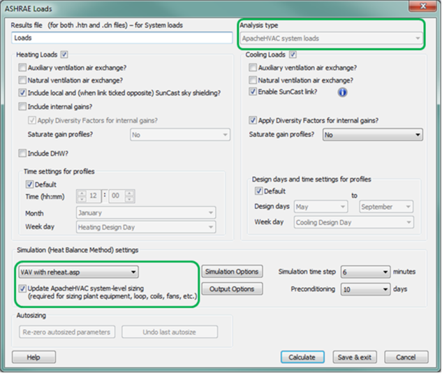
System load calculations and autosizing can be run from the System-level sizing button on the ApacheHVAC toolbar ( Figure 3-1 above), directly from within the ASHRAE Loads dialog ( Figure 6-13 below), or from the System load calculations action item in the System Prototypes & Sizing navigator. This third option is further described under in the System Prototypes & Sizing workflow navigator section below.
Figure 6 - 17 : ApacheHVAC system loads analysis type in ASHRAE Loads dialog
ASHRAE Loads supports flexible user control and differentiation between Room & Zone Loads, System Loads, and Dynamic Simulation. The following can be independently determined for the different types of loads analyses, with settings for each being retained by the software:
· Inclusion of internal gains;
· Diversity for internal gains;
· Saturation of profiles for internal gains, and if so, during all hours of non-zero profile values or just during occupied hours;
· Use of Design Day profiles when specialized gain profiles are needed specifically for Loads Analyses;
· A separate setting for inclusion of Diversity factors in dynamic simulations is provided in the ApacheSim dialog.
The user setting above are retained as user preferences for future loads and simulation runs.
In addition to the System Loads Calculation reports, there are also a number of tools available for checking the number of “unmet load hours” according to various criteria. This is explained in the next subsection immediately below.
Unmet Load Hours tests
Unmet load hours are any hours of operation when conditioned spaces are outside the throttling range for heating or cooling controls. While this test is performed automatically in the 90.1 Performance Rating Method (PRM) Navigator for the associated reports, this can readily be done as a manual check within Vista Results. To do so, complete all of the following steps (an example is provided below):
1. In Vista Results, select the conditioned spaces in the model from the Room Browser tree at left.
2. Select the Air temperature results variable.
3. Open the Range Test tool.
4. Date/Time: check the tick box below the list of week days and select When conditioned (incl. setback) from the drop-down menu next to this tick box.
5. Test: Between room setpoints (+/- differential tolerances)
6. Under Test temperatures in controlled band, tolerances in °F (or, for metric users, … in °C ), enter 2 for both heating and cooling if working in IP units and 1.11 for both if working in metric units (these settings will apply for most user most of the time; see further notes below).
7. Check the tick box for Averaged, shared hours (for ‘unmet hours’ test).
8. Click Apply.
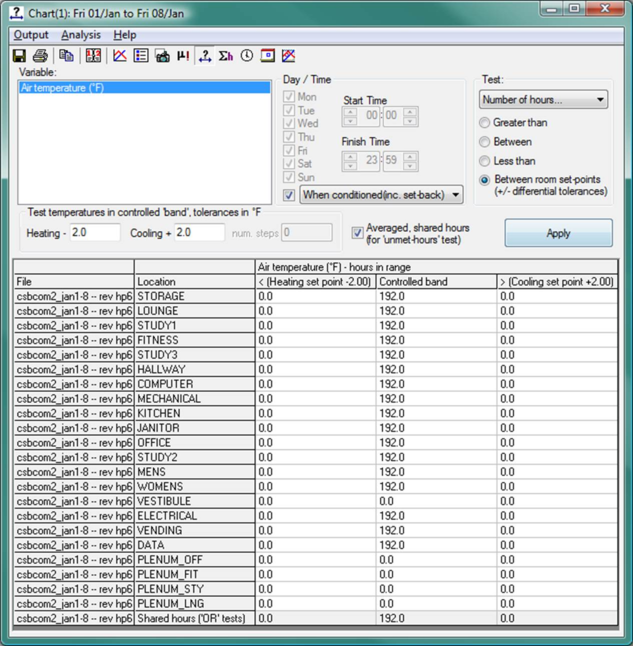
The range test below shows results for a system autosized perfectly to meet all loads for the simulation period of eight days in January (this test was aimed at confirming heating performance). This outcome may actually be less than ideal if meeting all loads under the most extreme conditions causes the system to be significantly oversized relative to more typical conditions. And, over a full year, even autosized systems will normally have some unmet heating or cooling hours as a result of varying conditions and related system dynamics or differences between the design sizing conditions vs. the simulation weather file. The results of an unmet loads hours test should, however, generally appear as in this example.
Figure 6 - 18 : Unmet Load Hours test performed using the Range Test tool in Vista Results
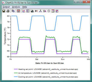
Figure 6 - 19 : Heating setpoint profile (purple), Cooling setpoint profile (blue), zone air temperature (green), and plant profile (red) for a selected space in the model.
As can be seen in Figure 6-15: Heating setpoint profile (purple), Cooling setpoint profile (blue), zone air temperature (green), and plant profile (red) for a selected space in the model. above, the profiles set in the Space Data dialog for a particular space (either via a Thermal Template, via System Schedules dialog, or manually) for heating and cooling setpoints are recorded at the time of simulation and can readily be placed on graph along with the zone/room air temperature. The profiles show the setpoints for occupied hours and setback for unoccupied hours.
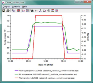
The right-hand graph shows the heating setpoint and room temperature once again with the Plant profile (red). The plant profile toggles between 0 and 1 to indicate the times during which the normal daytime setpoint should be fully met (future versions of the VE may use this profile to provide more detailed information regarding system status relative to setpoints, night-cycle operation, and so forth).
It is important to keep in mind that the heating and cooling profiles show the setpoint for occupied hours as a target for the morning start-up and after-hours operating periods. Thus you may see the room temperature lagging behind the setpoint profile, particularly in the early morning hours. The definitions below describe how unmet load hour tests use nighttime setback values while the modeled spaces are transitioning between nighttime setback and daytime setpoint. This avoids over-counting unmet hours.
Note that in the illustrative example on the preceding page there are some spaces in the model for which the hours in all three columns are zero. These spaces are plenums and an unconditioned vestibule. While they still have profiles assigned to them in Space Data (via System Schedules or manually) for timed heating and cooling setpoints and setback, they have their heating and cooling on/off profiles (on/off schedules) in Space Data set either individually or via thermal templates to “off continuously.” This is the essential means of indicating that a space in unconditioned with respect to unmet load hours tests.
When the VE detects heating and cooling on/off profiles set to “off continuously” and thus determines that a particular room is fully unconditioned, a nominal unconditioned values range of 20 ° C +/-80 ° C (68 ° F +/-144 ° F) is applied. This equates to an unconditioned heating value of -76 ° F (-60 ° C) just shy of the -80 ° F lowest external temperature ever recorded in the US, and an unconditioned cooling value of 212 ° F (100 ° C)—the boiling point of water. These values are recorded at the time of simulation as continuous setpoints for any fully unconditioned space.
Definitions of terms used in the Unmet Load Hours range test
The terminology used in the range test tools for unmet load hours is somewhat specialized. The following definitions may therefore be helpful in using the Range Test dialog for unmet load hour tests:
· When Occupied: All times for any particular room when occupancy is greater than zero.
· When room heated or cooled: Tests for hours out of range relative to the setpoint profiles at all times for each particular room, so long as the value for the on/off profile for either heating or cooling = on. If there are warm-up and after-hours operating periods over which the daytime setpoints are extended, this test will use daytime setpoints during these time periods. This test does not allow for room temperature transition from setback to setpoint.
· When plant profile on full: All times for a particular room during which the normal daytime setpoint should be fully met—i.e., fully excluding unoccupied/nighttime operation (outside of “opening hours”) and both morning start-up and after-hours operation.
· When conditioned (incl. setback): Tests for hours out of range relative to setpoints, applying the unoccupied/nighttime setback values to any morning start-up and after-hours operating periods during all times for a particular room when the on/off heating or cooling profile = ON. This test assumes, for example, that the full morning warm-up period will be needed to raise a particular zone from the setback temperature to the daytime setpoint, and therefore does allow for room temperature transition from setback to setpoint.
· Between room setpoints (+/- differential tolerances): Test to count hours in three categories:
o Below the heating setpoint minus the heating control band tolerances
o Between room setpoints, +/- the set control band tolerances
o Above the cooling setpoint plus the heating control band tolerances
· Test temperatures in controlled band, tolerances in °F: These values set the added tolerance above and below the setpoints that should be applied to determine when a temperature is “out of range.” The tolerances allow for the throttling or control of HVAC parameters such as variable water and air flow rates in coils and ducts to address loads. The pre-defined systems all reference profiles that have names beginning with “HVAC,” and so long as they are changed only via the System Schedules dialog, these profiles are maintained with standard throttling ranges relative to the heating and cooling setpoints. Unless you’ve set up your own HVAC controller profiles or have revised values in the pre-defined “HVAC” profiles within ApPro, the standard 2 ° F for both heating and cooling when working in IP units (1.11 ° C when in metric) should be used here. If you have set up custom control profiles, you will need to set these tolerance values to allow for the throttling range in the custom profiles.
· Averaged, shared hours (for ‘unmet hours’ test): This looks at average temperature over the full one-hour period in each room for each hour and then adds any particular out-of-range hour to the total “shared hours” tally only once, regardless of how many rooms or zones were out of range during that hour. The “shared hours” total of each column is displayed in the bottom row of the table.
With all conditioned spaces selected, the total of shared hours reported in the bottom row as outside the control ranges for both heating and cooling are collectively the Unmet Load Hours.
A space temperature is considered out of range (under-heated or under-cooled) for any hour when the average temperature for that hour is below the heating setpoint less the control band tolerance or above the cooling setpoint plus the control band tolerance. The “shared hours” might be thought of as a logical ‘OR’ test, with each hour counted only once when any one or more rooms in the currently selected set of rooms is/are out of range.
Understanding loads for ApacheHVAC components in Vista Results
It’s important to understand what you’re looking at when viewing loads for ApacheHVAC components within Vista Results view. The following is meant to touch on just a few points that may be less obvious in terms of how the numbers you see in the results relate to the capacity of the components and the loads that they convey to heating and cooling plant equipment.
Coils are relatively more straightforward in that their capacity or loading is a function of design inputs:
· For simple coils, the capacity set in the coil dialog will be the capacity, regardless of conditions on either the air or water side of the coil. Regardless of system-level plant equipment capacity, in the case of a simple coil all simulated load up to the capacity set in the dialog will be passed to the connected water loop or directly to the heating or cooling source if no water loop is present.
· For advanced coils, the capacity of the coil is a function of the relationship between the design conditions and the actual conditions at any given time step, including the temperature and flow rate of the connected water loop. The coil will be restricted to delivering only as much heating or cooling as is feasible given the combination of sensible and latent loads it sees and the loop water temperature and flow rate it has to work with at that time. The resulting load will be passed to the associated water loop.
Water loops will contribute to the load seen by a boiler or chiller: heat rejected to the water loop by pumps will add to or subtract from the load placed upon the loop by coils and other devices.
Room units, unlike coils, have heating and cooling effects associated with the presence of their thermal mass within the conditioned space: Regardless of whether it is OFF (i.e., not active or presently engaged) or ON, the thermal mass of any room unit will play a role in adding heat to or removing heat from the space. All room units will thus have a load profile differing at least somewhat from the load profile seen by the heating or cooling source or loop to which they are coupled.
For example, a radiator will heat a room less as its mass is warming up and will continue to heat the room after the flow of hot water to it is turned off. And, even if it never turns on, a radiator will absorb a minor cooling load while sitting idle in a space as the space grows warmer. Thus at the end of a hot summer day when the air conditioning runs just to closing time, a radiator may contribute ApHVAC Room Unit Cooling Load (via stored “coolth”) when the airside AC system shuts down and the room begins to grow warmer.