Zone-level loads, sizing and related setup procedures
The zone-level autosizing process sets zone-level and airside control inputs in the context of basic system-level parameters. Depending upon the specific system type, these include the following parameters:
· zone-level heating and cooling load oversizing factors
· zone-level airflow for VAV boxes, fan-coil units, fan-powered boxes, active chilled beams, etc.
· outside-air ventilation rates as well as CO2 sensor control thresholds, where DCV is employed
· exhaust airflow and inter-zonal transfer airflows (typically as make-up air for exhausted air)
· reheat coil leaving air temperatures and flow rates
· radiator and chilled ceiling panel water flow rates (as of version 6.5)
· outside-air economizer damper minimum flow rates (incl. optional ASHRAE 62.1 calculations)
· outside-air economizer dry-bulb temperature high limits*
· energy recovery engagement, sensible and latent effectiveness, and device power*
· coil leaving air temperatures, temperature resets, and zone humidity control*
For prototype systems, the zone-level autosizing process provides means of engaging or disengaging system features, such as outside air economizers and airside energy recovery, from within the System Parameters dialog, in addition to manually changing these within the Loads Data spreadsheet for each system or within the ApacheHVAC airside network itself. The controllers in pre-defined systems also use pre-defined control profiles (which you may also use as you see fit). This allows system-operating schemes for unoccupied hours—e.g., temperature setback only, setback with fan cycling, or setback with fan cycling but no outside air—to be selected along with system schedules and setpoints. While these parameters and operating schemes can be manually changed, the dialogs provide basic inputs and automation for pre-defined systems.
While rooms or zones may be adequately conditioned with just the first stage of sizing completed, energy consumption for grossly over or undersized equipment will be far from what is should be. This will be particularly true in the case of performance for grossly oversized hot-water boilers and air-cooled or water-cooled chillers using pre-defined bi-quadratic performance curves. System-level loads calculation and sizing, which applies to coils, fans, water loops, chillers, DX cooling, boilers, heat pumps, etc., must be completed in order to appropriately scale equipment capacities and performance curves and thus to obtain performance and energy consumption results that reflect real-world applications.
The System Schedules and Setpoints dialog (see additional description below) sets room heating and cooling set points, operating schedules, including start-up and after-hours operation, and the control scheme to be used during unoccupied hours. It does so via automated editing of a pre-defined set of profiles that are referenced within the prototype systems and also applied to Space Data in the Apache Thermal view. The application of heating and cooling set points from the System Schedules dialog to Space Data for each conditioned space provides the fundamental basis for autosizing.
The System Parameters dialog (see additional description below) provides initial inputs for many of the zone- and system-level parameters in the list above, such as zone load oversizing factors and both air-handler and zone coil leaving air temperatures, as inputs to the autosizing of zone-level airflows, etc. It should be noted that oversizing factors are separately set with coils, water loops, and other heating and cooling equipment that is autosized only in the system-level stage of the process.
The ASHRAE 90.1 Performance Rating Method (PRM) Navigator within the VE provides additional interface dialogs and tools for ASHRAE 62.1 ventilation rates, exhaust airflow settings, and application of PRM Baseline fan curve inputs. The PRM Navigator interface is described in a separate user guide. The ApacheHVAC path to these parameters is described below.
The System Prototypes & Sizing navigator is an optional path for autosizing that is functionally equivalent to the set of five toolbar buttons within the ApacheHVAC view ( Error! Reference source not found. ). Using this workflow navigator, which includes some minor additional features, requires that the target ApacheHVAC system file is named “proposed.asp”. This file name must be in place prior to using either System Parameters or Room Load Calculations. If not, the parameter changes and/or sizing process will not populate the Loads Data spreadsheet according to the rooms or zones assigned to the correct target system. When using this workflow navigator, the “proposed.asp” target system name must also remain in place (or be reinstated) for the Assign system parameters and room sizing data action within the navigator. The ApacheHVAC file name can be subsequently changed without consequence.
The naming convention described above is not be required when using the five-button toolbar within ApacheHVAC for System Schedules and Setpoints, System Parameters, Room and Zone Sizing, System and Plant Equipment Sizing, and System Sizing Reports, as described below.
Model set up for zone-level system autosizing steps
Unless the model has exceptionally small number of thermal zones, conditioned spaces and related thermal zones in model should first be grouped according to system or air-handler assignment using an appropriate Room Grouping Scheme.
Loading HVAC systems from library or project folders
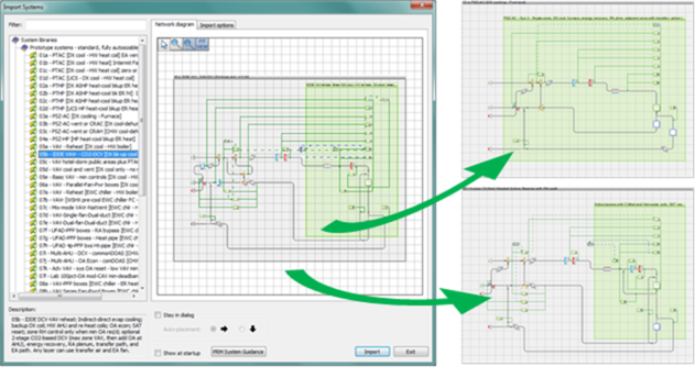
Figure 6 - 2 : Open ApacheHVAC, load selected systems from the HVAC Prototype Systems Library as needed, and save the file.
Additional systems can be loaded at any time and additional sizing runs performed as needed. Prototype systems can be modified or used as resources from which to copy elements for customizing or extending the capabilities of a particular system. For all but advanced users, however, it is recommended that initial system sizing and brief test simulations are completed prior to modifying the system configuration, components, or controls (substantial experience with ApacheHVAC is also recommended).
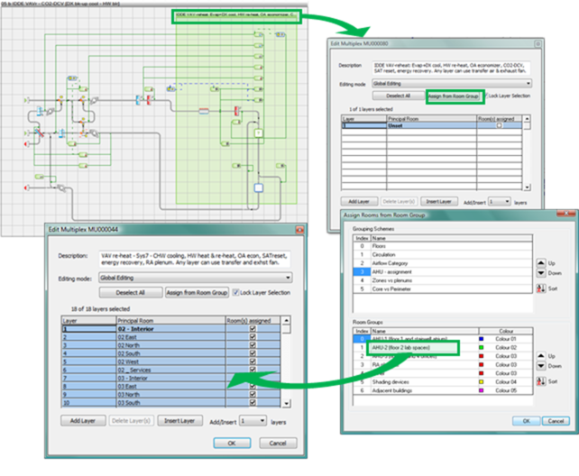
Figure 6 - 3 : Use Edit Multiplex to assign user-defined groups of rooms or zones to each prototype system.
TIP: If you hold down the Ctrl key and clicking on the Room Group Index Numbers, you can select more than one Room Group for simultaneous assignment to a single HVAC network.
Once the rooms or zones have been assigned to all HVAC system networks in the current HVAC system file, proceed to using the following five buttons of the System Sizing toolbar in ApacheHVAC to set up and autosize the systems.
System Schedules and Setpoints
Models created in versions of the software older than VE 2018 use an independent System Schedules and Setpoint dialog to set room heating and cooling set points, operating schedules, including start-up and after-hours operation, and the control scheme to be used during unoccupied hours. This dialog is accessible in VE 2018 for models created in an older version of the software where the ApacheHVAC file has not been manually upgraded. For models created in VE 2018, as well as for legacy models where the ApacheHVAC file has been upgraded, this toolbar button will not be selectable. For detailed information about the legacy System Schedules and Setpoints dialog, please refer to an older version of this User Guide.
System Operating Schedules
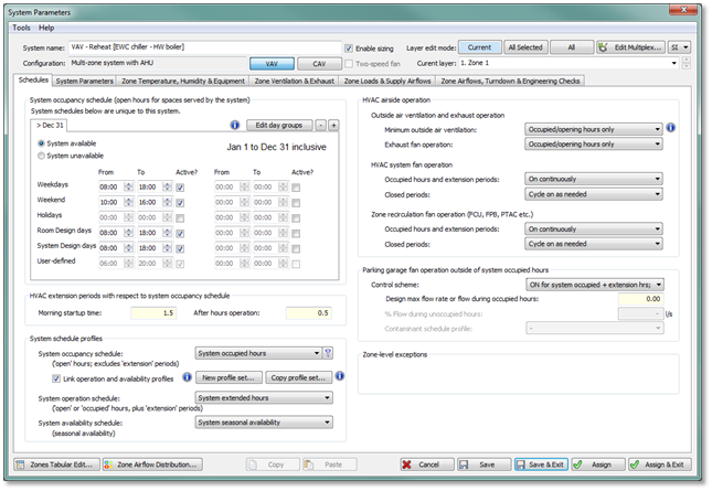
Figure 6-4: The Schedules tab of the System Parameters dialog has two main functions: a) editing and creating sets of coordinated HVAC profiles used in system controllers and Space Data, and b) setting parameters that determine when and how HVAC fans, ventilation, and economizers will operate outside of occupied hours.
To define patterns of operation at system level, a default set of three profiles are provided to function as schedules for operation of various equipment and controls:
System occupancy schedule:
System occupied hours – on during ‘open hours’ or ‘occupancy period’ as set for HVAC systems.
System operation schedule:
System extended hours – on during the ‘occupied’ plus ‘extension’ periods.
System availability schedule:
System seasonal availability – periods of the year when the system is available for operation, and will remain in operation unless constrained by the profiles above—i.e., this profile is on 24-hours/day except during ‘shut-down’ date ranges.
Dates and hours for these profiles are defined in the System occupancy schedule frame above. The “System occupied hours” profile is edited directly when modifying the operating hours in this frame. The “System extended hours” profile is a copy of the “System occupied hours” profile with the inclusion the ‘Morning startup time’ and ‘After hours operation’ parameters defined in the “HVAC extension periods with respect to system occupancy schedule” frame. The “System seasonal availability” profile is also a copy of the “System occupied hours” profile, but all date ranges of unavailability have all ‘Active’ boxes unchecked and all date ranges of availability have all ‘Active’ boxes checked and times set to 24 hours/day of availability.
Additional sets of these three profiles can be created for mixed-use buildings or other applications wherein some systems will operate on differing schedules.
The default profiles described above are compact profiles, which support linked editing and efficient workflow; however, user-defined weekly, yearly, and free-form profiles can be selected for use in the Schedules tab of the System Parameters dialog. When other profile types are selected, the three profiles will no longer be linked and must be edited in ApPro.
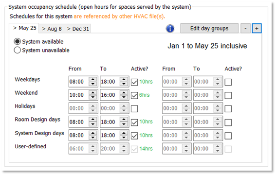
Figure 6-5: The System occupancy schedule frame of the Schedules tab of the System Parameters dialog allows for direct editing of the compact profile “System occupied hours”.
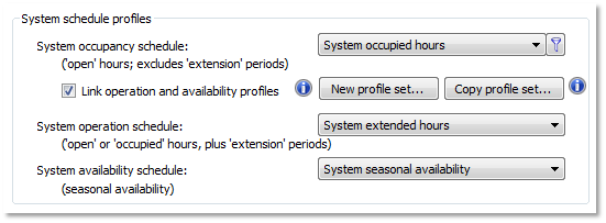
Figure 6-6: The System schedule profiles frame of the Schedules tab of the System Parameters dialog allows users to change the profiles used for each of the three main schedule applications.
‘Link operation and availability profiles’ is available only when the selected ‘System occupancy schedule’ is a compact profile. When this box is checked, the Operation and Availability profiles are coordinated with the ‘System occupancy schedule’ compact profile in keeping with the ‘HVAC extension periods’ and system availability, as indicated on the date-range tabs of the ‘System occupancy schedule’ editing facility. If a set of compact profiles with coordinated names is not already selected, the profiles currently selected for Operation and Availability will be replaced by profiles auto-coordinated with the ‘System occupancy schedule’ compact profile when the link box is checked.
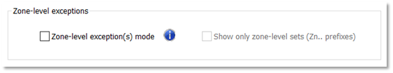
Figure 6-7: The ‘Zone-level exception(s) mode’ allows selection of schedule profiles for a specific zone or zones (room or rooms, when working with ‘Room’ components rather than zones).
Airside System Fans, Outside Air, and Exhaust Operating Schedules
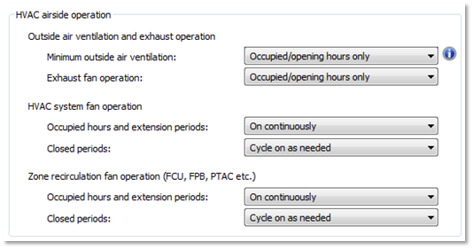
Figure 6-8: The HVAC airside operation frame of the Schedules tab of the System Parameters dialog allows users to change the operation of airside HVAC system fans for common applications.
Settings for “Minimum outside air ventilation” within a system include the following options:
Occupied/opening hours only – on during ‘open hours’ or ‘occupancy period’ as set for HVAC system
Occupied + extension hours – on during the ‘occupied’ plus ‘extension’ periods
All hours – always on
In the case of dedicated outside air systems and exhaust driven ventilation, the period set for “Minimum outside air ventilation” determines when this minimum will be delivered, including the necessary system fan operation. For all other system types, this determines only when the “Minimum outside air ventilation” requirement will be enforced via the minimum setting for an outside air damper or equivalent, if the system fan is operating.
Settings for “Exhaust fan operation” are identical to those offered for “Minimum outside air ventilation” but may be limited in availability based upon the selection for minimum ventilation. The exhaust fan may only operate during times when ventilation air is available to make up the exhaust in the system.
Settings for “HVAC system fan operation” > “Occupied hours and extension periods” include the following options:
On continuously – always on
Cycling (ventilation provided otherwise) – cycles on only when needed
When the cycling option is selected, there may be times during occupied hours that the system fan does not run. In this instance, no ventilation air will be provided by the system.
Settings for “HVAC system fan operation” > “Closed periods” include the following options:
On continuously – always on
Cycle on as needed – system fan runs only where there is a call for heating or cooling from a zone served by the system
Off – always off
The same options are provided for Zone recirculation fan operation as for HVAC system fan operation during occupied and closed periods.
Parking Garage Fan Control Schemes and Operating Schedules
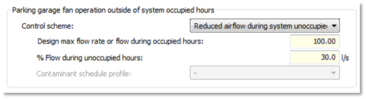
Figure 6-9: The Parking garage fan operation frame of the Schedules tab of the System Parameters dialog allows users to change the operation and flow in parking garage fans for a system
The following control schemes are available for specifying the operation of parking garage fans:
ON for system occupied hrs; otherwise OFF – parking garage fans operate at full design flow rate only during system occupied hours (excludes extension periods)
ON for system occupied hrs + extension hrs; otherwise OFF – parking garage fans operate at full design flow rate during system occupied hours and extension periods
ON continuously at full design flow rate – parking garage fans always operate at full design flow rate
Reduced airflow during system unoccupied hours – parking garage fans operate at full design flow rate during system occupied hours and at a reduced flow rate during system unoccupied hours
Modulate airflow per variation of contaminants, etc. – parking garage fans operate per a Contaminant schedule profile
When parking garage airflow is modulated per variation of contaminants, the option to specify a “Contaminant schedule profile” is provided. An example schedule, “Parking garage fan flow modulation”, represents full design flow operation at peak commuting hours for a typical office building, half of the design flow during other typically occupied hours, and zero design flow during unoccupied hours. Any modulating profile may be used instead.
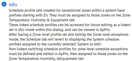
Schedule profile sets created for exceptional zones within a system have prefixes starting with Zn. They must be assigned to those zones on the Zone Temperature, Humidity, & Equipment tab.
These linked schedule profiles can be accessed for future editing as a linked set in this mode within the Schedules tab of the System Parameters dialog, and can be viewed in ApPro.
After Saving a Zone-level profile set and exiting the Zone-level exceptions mode, the Schedule tab will revert to displaying the System schedule profiles assigned to the currently selected ‘System to edit’.
Non-linked switching schedule profiles for zone-level schedule exceptions must be defined and edited in ApPro, then assigned to those zones on the Zone Temperature, Humidity, & Equipment tab.
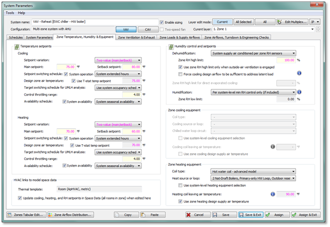
Figure 6-10: The Zone Temperature, Humidity & Equipment tab of the System Parameters dialog allows users to edit the temperature and humidity setpoints, as well as parameters for unmet load hour analysis, for specific zones within a system.
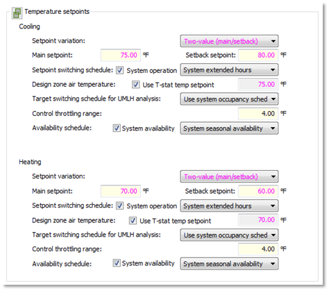
Figure 6-11: Temperature setpoints section of this dialog is initially populated with linked setpoints for each particular zone passed to ApacheHVAC from Space Data. These linked values and the type of setpoints can be overridden. Likewise, the associated schedule information for each zone is, by default, linked to system level schedules, but can be overridden here.
Control throttling range defines the temperature range over which zone-level heating and cooling controls operate. The default throttling range of 4°F (2K), for example, provides a range of 4°F (2K) for flow and temperature modulation in a variable air volume (VAV) system. In the example of cooling operation, the flow through a single-duct terminal unit would modulate from its minimum flow to maximum flow over a range of 2°F (1K) and the supply air temperature (SAT) would reset over a range of 2°F (1K).
System availability schedule checkboxes for cooling and heating setpoints can be unchecked only when a Chilled Ceiling or Radiator room unit is present in a system, or one of the following links exists in the network:
· FCU Cooling airflow CAV/2sp/VAV
· DOAS PTAC/PTHP Cooling airflow CAV/2sp/VAV
· PTAC/PTHP cool airflow CAV/2sp/VAV
· UCS Cooling airflow
· FCU Heating airflow CAV/2sp/VAV
· FPB Secondary airflow CAV/2sp/VAV
· DOAS PTAC/PTHP Heating airflow CAV/2sp/VAV
· PTAC/PTHP heat airflow CAV/2sp/VAV
· Dual-fan dual-duct zn heat airflow
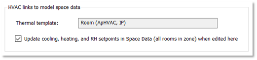
Figure 6-12: The “HVAC Links to model space data” section of the dialog provides the name of the room thermal template associated with the room or zone on the currently selected multiplex layer, as well as a checkbox to determine if edits to the temperature and RH setpoints in ApacheHVAC will feedback to the model, resulting in updates to these values within Space Data.
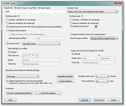
Figure 6-13: The Room/Zone Load Calculations toolbar button (or the equivalent step in the System Prototypes & Sizing navigator) runs ASHRAE Loads and populates the System Parameters interface for each network with loads results. Other relevant data, such as room volumes, is populated when rooms or zones are assigned to multiplex layers. The loads data and other settings in the System Parameters dialog for zone-specific airflow configurations and calculation of ASHRAE 62.1 ventilation rates feed into the calculation of zone airflows and related parameters.
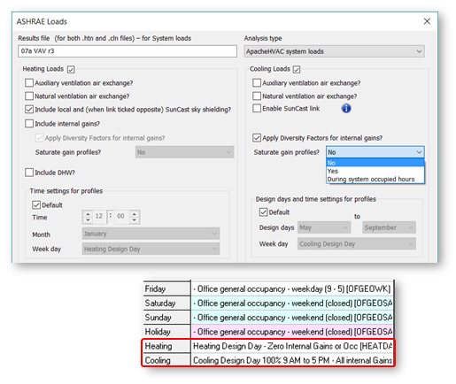
Figure 6-14: Options for running ASHRAE Loads including diversity for internal gains, internal gain profile saturation, and design day profiles
ASHRAE Loads supports flexible user control and differentiation between Room & Zone Loads, System Loads, and Dynamic Simulation. The following can be independently determined for the different types of loads analyses, with settings for each being retained by the software:
· Inclusion of internal gains;
· Diversity for internal gains;
· Saturation of profiles for internal gains, and if so, during all hours of non-zero profile values or just during occupied hours;
· Use of Design Day profiles when specialized gain profiles are needed specifically for Loads Analyses;
· A separate setting for inclusion of Diversity factors in dynamic simulations is provided in the ApacheSim dialog.
The user setting above are retained as user preferences for future loads and simulation runs.
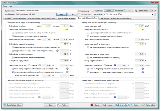
Figure 6-15: The System Parameters dialog provides access to viewing and editing numerous parameters for system configuration, sizing, and control options. Edited parameters are applied to system components and controllers through ‘system parameter links’ upon clicking ‘Assign’. The ApacheHVAC User Guide part D - System Parameters Interface for HVAC Networks describes this in greater detail.
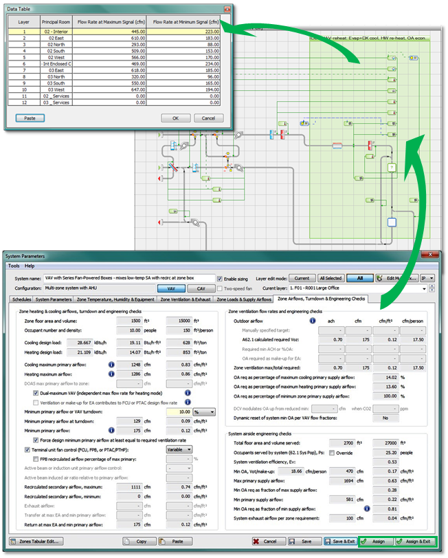
The Assign button in the System Parameters dialog assigns values to system components and controllers. This is also done automatically upon completion of zone-level autosizing when the ‘Update ApacheHVAC zone-level autosizing’ box is checked in ASHRAE Loads. Viewing the zone cooling and heating airflow rates for all multiplex layers confirms that this stage of autosizing has been satisfactorily completed.