Solar Radiation Fundamentals
To a good approximation, the sun is a black body radiator with a surface temperature of 5800K. The energy it radiates produces a radiation flux at the top of the earth’s atmosphere which over the course of a year averages to 1353 W/m 2 . Filtering by gases in the atmosphere and by cloud and particulates means that fluxes at the earth’s surface are variable and typically considerably less than this figure. Further factors influencing solar radiation at ground level are varying sun angles and diffusing of the radiation by the atmosphere.
Solar radiation incident on building surfaces can be broken down into three main components: direct (beam) radiation emanating from the region of the sky near to the sun’s disc, diffuse radiation from the sky vault, and radiation scattered by the ground. Direct radiation is significantly modified by shading by nearby buildings and landscape features.
Solar radiation enters the building through glazing and is absorbed (after repeated scattering) by internal surfaces. Part of this radiation may be lost by being re-transmitted out of the building through glazing. The effect of absorption and scattering by exterior surfaces (both opaque and transparent) is also significant.
Meteorological Solar Variables
ApacheSim is driven by actual weather recorded at hourly intervals and stored on a simulation weather file. The variables on the file relating to solar radiation are:
· Direct solar radiation measured perpendicular to the beam (W/m2)
· Diffuse solar radiation measured on the horizontal plane (W/m2)
· Solar altitude and azimuth (º)
The solar altitude and azimuth are calculated from the location of the site where the weather was recorded, together with time zone and summertime clock adjustment information. This information is also used by the programs SunCast and SunCast Lite to generate shading data for ApacheSim, and it is important that the same location data is used in both cases.
Calculation of Incident Solar Flux
ApacheSim calculates, at each time-step, the solar flux incident on every external building surface. The components of the incident flux are calculated as follows.
The direct solar flux, Idir, is
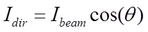

(37)
where

is the direct solar flux (W/m
2 ) incident on the surface

is the solar flux (W/m
2 ) measured perpendicular to the beam

is the angle of incidence
The diffuse solar flux has components radiated from the sky and the ground:
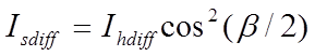
(38)
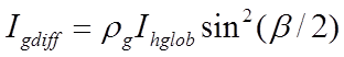
(39)
where

is the diffuse sky solar flux (W/m
2 ) incident on the surface,

is the diffuse sky solar flux (W/m
2 ) on the horizontal plane,

is the inclination of the surface,

is the diffuse ground solar flux (W/m
2 ) incident on the surface,

is the solar reflectance (albedo) of the ground,
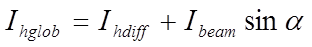
is the total solar flux (W/m
2 ) on the horizontal plane,

is the solar altitude.
This analysis covers the case where the sky diffuse radiation is assumed to be isotropic, the factors involving

arising from integration of this isotropic radiation over solid angle.
If the user selects the anisotropic diffuse solar radiation model from the Simulation Options menu the calculation designates a portion of the diffuse radiation circumsolar, which it treats as if it emanated from the sun position. The proportion of the diffuse radiation designated circumsolar varies with the intensity of the beam radiation, following a variant of the method proposed by Hay[11] with adjustments applied for diffuse shading.
Shading & Solar Tracking
Shading of the beam component of solar radiation may be modelled in three ways in ApacheSim:
· Shading and solar tracking calculations performed by SunCast
· Shading calculations performed by SunCast Lite
· Shading calculations performed by ApacheSim for construction-based shading devices
SunCast and Suncast Lite shading applies to both glazed and opaque surfaces. Construction-based shading only applies to glazing.
The SunCast Shading File
Shading data generated by SunCast for the 15th day of selected months is stored on a shading file with extension ‘.shd’. The data for a given month comprises hourly data describing the exposure of both exterior and interior building surfaces to beam solar radiation. If the shading file is specified at run time, ApacheSim reads the data and uses it to modify the beam component of solar radiation, and when the beam enters the building through glazing, to assign it to interior surfaces. If requested in SunCast, the shading file will also contain diffuse shading factors indicating, for each exposed surface of the building, the degree of shading from the sky vault.
The data on the SunCast shading file records a shading factor for each exterior building surface receiving beam solar radiation. In the case of glazed elements, the file also records which interior surfaces are irradiated by the beam after it has passed through the glazing, and to what extent (expressed in terms of sun-patch area projected perpendicular to the beam). If a receiving surface is itself glazed, the radiation is traced on through this element to other receiving surfaces beyond, and so on. This process is referred to as solar tracking.
Any holes in building elements are treated by SunCast as perfectly transparent to the solar beam.
The SunCast Lite Shading File
SunCast Lite generates monthly shading data in a similar format to SunCast, but the data on its shading file is limited to external shading. It does not include solar tracking data. If a SunCast Lite shading file is specified at run time, ApacheSim uses this data to modify the beam radiation falling on exposed surfaces, but then distributes it internally as if it were diffuse radiation.
Construction-based Shading Devices
In APcdb (the constructions database manager) local shading devices may be defined for glazed constructions. These take the form of side-fins, overhangs and balconies, and may also be used to represent window recesses. Local shading devices apply to rectangular windows only, and are idealised as objects of infinite extent. An overhang, for example, is modelled as extending indefinitely to the right and left of the window.
APcdb also allows for the addition of external shutters or louvres and internal blinds or curtains. These are assigned parameters indicating their solar characteristics and may be raised and lowered at set times or in response to variables such as solar intensity.
Construction-based shades are attached to all instances of the glazing construction. These objects shade both direct and diffuse solar radiation. They also shade long-wave sky radiation. Unlike the shading calculations performed by SunCast and SunCast Lite, the calculations for these shading devices are carried out by ApacheSim at run-time. The results of these calculations are then combined with any SunCast or SunCast Lite shading.
Distribution of Tracked Beam Solar Radiation
When a SunCast shading file is in use, and contains shading data for the current month, ApacheSim applies the shading data in the following way.
At each time-step, the radiation intercepted by each exterior receiving surface is calculated from the incident beam solar flux, taking account of the surface geometry and any external shading factor.
If the receiving surface is transparent, ApacheSim calculates the transmission and absorption of the beam. The attenuated transmitted beam is then tracked through successive interactions with building surfaces, following the tree-like data structure recorded on the shading file. Any radiation falling on an opaque element is partially absorbed and partially reflected, using an assumed solar absorptance of 0.55. Beam radiation falling on a transparent element is transmitted, absorbed and reflected in accordance with the element’s properties. Radiation reflected from opaque or transparent surfaces is returned to the adjacent room for later distribution as diffuse radiation. Transmitted beam radiation is tracked on further receiving surfaces. The process terminates when all components of the beam have either encountered opaque surfaces or left the building through transparent elements. (Having left the building the beam may subsequently strike another building surface; however, ApacheSim does not currently account for such components.).
The distribution of tracked radiation is further complicated by the following factors:
1. The tracking process is actually performed twice at each time-step, to allow interpolation between the data recorded on the shading file for successive hours.
2. Adjustments are made to the projected sun-patch surface areas read from the shading file, to allow for the difference in solar position between the day being simulated and the day for which the shading calculations were performed.
3. The shading described by the factors on the shading file may be supplemented by local shading from side-fins, overhangs and balconies, as well as shading by external shutters and internal blinds.
4. The effects of window frames are accounted in the calculation of glazing transmission, absorption and reflection. Window frames use the solar absorptance value assigned in APcdb.
5. Absorption in transparent elements is split into two components, representing the effective absorption on the internal and external surfaces of the element. These components of absorption are later distributed in appropriate proportions to the adjacent spaces.
Calculation of Incident Diffuse Solar Radiation
Diffuse radiation incident on an exposed surface is the sum of components from the sky, the ground, and certain types of shading object. Shading objects block diffuse sky solar radiation to a degree determined by a diffuse shading factor.
Diffuse shading factors for remote shading objects are calculated optionally by SunCast (or assumed to be 1 if not calculated). This type of shading applies to both glazed and opaque surfaces.
Diffuse shading factors for construction-based shades defined in APcdb and classified as ‘local’ (side-fins, overhangs and balconies) are calculated for each instance of the construction occurring in the model. Where both remote and local shades apply to the same surface, their diffuse shading factors are combined by taking the lower of the two factors. This gives a conservative estimate of the degree of shading.
SunCast and ‘local’ shading objects are assumed to scatter ambient radiation, as well as blocking diffuse radiation from the sky. This gives rise to an additional term in the diffuse incident flux. For the purpose of estimating this flux, shading objects are assumed to be vertically oriented, adjacent to a large vertical wall, and both wall and shading object are assumed to have a reflectance of 0.3. Ground reflection is accounted for, but direct and circumsolar radiation is excluded from the calculation.
Construction-based shades of the ‘external’ type (shutters and louvres) have a sky shading factor and a ground shading factor set in APcdb (both of which may optionally be calculated from the direct shading characteristics). These factors attenuate the radiation incident on the glazed element from the sky, the ground and the other types of shading object. Radiation scattered by shading devices of this type is ignored.
Distribution of Diffuse Solar Radiation
The diffuse component of solar radiation incident on an external glazed element – the sum of components from the sky and the ground – is partially transmitted and partially absorbed in the element. The transmitted portion is distributed over the interior building surfaces as follows.
In simple cases the diffuse radiation entering a room through a glazed element is distributed over the other surfaces in the room in proportion to their areas. An exception to this rule may apply in the case of glazed, external receiving surfaces. If the shape factor implied by the area-weighted distribution is greater than the maximum theoretical shape factor between the receiving surface and the source surface (given their areas and relative orientation) the shape factor is reduced to the theoretical maximum. The radiation deficit is then spread over the other receiving surfaces in proportion to their estimated shape factors. This exception prevents windows in the same façade from radiating directly to each other. Such windows are treated effectively as one large window.
Surfaces receiving diffuse radiation distributed in this way reflect, absorb and (if transparent) transmit it in appropriate proportions. ‘Holes’ are treated as perfectly transparent. Reflected diffuse radiation is combined with any reflected tracked radiation in the room and distributed over the room’s surfaces on the basis of an acceptance weighting in which each surface is irradiated in proportion to its area multiplied by the sum of its absorptance and its transmittance. The resulting distribution emulates the distribution that would result from apportioning the radiation on a strictly area-weighted basis and successively repeating the process for the reflected components until no radiation remained.
Radiation transmitted through transparent partitions in the course of these processes is treated in a similar way to radiation entering the building from outside. No shape factor adjustment is applied, however.
A portion of any radiation distributed to external windows is lost by transmission back out of the building.
The above steps are repeated up to 10 times to distribute the diffuse radiation through the building. Any residual radiation at the end of the process is assigned to room surfaces in a final modified acceptance distribution.
Special Element Adjacencies
Windows in elements assigned the adjacencies ‘Outside air with offset temp.’ and ‘Temp. from profile’, and those in partition elements linking to inactive spaces, receive no external solar radiation. Any radiation transmitted out of the building through such windows in the course of the solar distribution is lost from the model.
Distribution of Non-tracked Beam Solar Radiation in Apache
When solar tracking does not apply (that is, when a SunCast shading file is not in use, or is in use but contains no data for the current month) beam radiation is distributed over the building interior in the same way as diffuse radiation.
Solar Transmission, Absorption & Reflection by Glazing
Glazing Solar Characteristics
The characteristics of glazed constructions are calculated from first principles from data entered in APcdb.
The data for a glazed construction is as follows:
· Glazing data:

External surface emissivity (used if not set for external pane)

Internal surface emissivity (used if not set for internal pane)

Optional user-specified external surface resistance (m
2K/W)

Optional user-specified internal surface resistance (m
2K/W)
· Layer data:
dj Thickness of glazing layer j
λj Conductivity of glazing layer j (W/mK)
Gas j Gas filling cavity (used with layer thickness and orientation to
calculate convection coefficient when the latter is not specified
explicitly)
hcj Convection coefficient for cavity (W/m2K) (used with adjacent pane
emissivities to calculate cavity resistance when the latter is not
specified explicitly)
rj Thermal resistance of cavity (m2K/W) (may be user-specified or
derived from cavity resistance and adjacent pane emissivities)

Normal-incidence solar transmittance of glazing layer j
ρej Normal-incidence solar reflectance of glazing layer j for radiation
incident from outside
ρij Normal-incidence solar reflectance of glazing layer j for radiation
incident from inside
nj Refractive index of glazing layer j
εej Outside surface emissivity of glazing layer j
εij Inside surface emissivity of glazing layer j
· Frame data:

Frame area as percentage of total area (%)
Rf Frame resistance, excluding surface resistances (m2K/W)
αf Frame solar absorptance
· Local, external and internal shading data
From this data the program calculates the following derived parameters for the construction as a whole:
· Solar transmission, absorptance and reflectance parameters at 10 angles of incidence spaced at 10 degree intervals.
· Parameters describing the distribution of solar absorption within the construction
· Separate U-values for the glazing and the frame, and a net U-value combining the glazing and frame U-values.
These calculations, which are carried out in a pre-simulation stage, are performed as follows.
For each glazing layer (pane) the solar characteristics are checked for consistency. An analysis based on the Fresnel equations is carried out for a pane having the given layer refractive index and an absorption parameter (extinction coefficient) that is adjusted to match the given pane absorptance. This is done for two rays with perpendicular polarisations, and the results are combined to give normal-incidence transmittance, absorptance and reflectance values. These are then compared with the values entered for these parameters. The most likely cause of a discrepancy in this comparison is the presence of a reflecting film on the glass surface. In this case the discrepancy is corrected by adding a reflecting film with properties chosen to match the characteristics entered. When the discrepancy cannot be corrected by a modification of this sort, the refractive index is adjusted to produce a match. The derived characteristics are then used to produce transmittance, absorptance and reflectance parameters for 10 incidence angles, again using the Fresnel equations applied to rays of two polarisations.
The solar characteristics of the construction as a whole are then calculated for the 10 incidence angles and the two polarised rays. This process in general involves consideration of an infinite number of reflections at glazing/air interfaces. The result is a set of solar transmission, absorptance and reflectance parameters at 10 angles of incidence, the absorptance characteristics being further resolved according to where in the construction the absorption occurs. The absorption parameters are then simplified, without any compromise of accuracy, by replacing each absorption by equivalent absorptions at the external internal surface of the constructions, using an equivalent circuit representation involving the thermal resistances of the layers.
Glazing Solar Interactions during Simulation
During a simulation, whenever solar radiation strikes a glazed surface the interaction of the radiation with the glazing is calculated using the construction’s solar parameters.
Portions of the incident radiation are transmitted, absorbed, and reflected. For direct (beam) radiation the appropriate angular characteristics are used. For diffuse radiation, the calculation uses hemispherically averaged characteristics obtained by integrating over the incidence angles with a weighting for solid angle. Any frame forming part of the construction is assumed to have a transmittance of zero and an absorptance as set in the frame data.
External shutters/louvres and internal blinds/curtains participate in the interaction according to their parameters as specified in APcdb.
Solar Absorption & Reflection by Opaque Surfaces
External opaque building surfaces absorb and reflect solar radiation according to their solar absorptance as assigned in APcdb. SunCast and SunCast Lite shading data is applied to external opaque surfaces, and SunCast shading data is applied also to internal opaque surfaces.
