Electric Water-cooled Chillers
The electric water-cooled chiller model simulates the performance of an electric chiller cooled by condenser water from an open cooling tower. The model uses default or user-defined chiller performance characteristics at rated conditions along with three performance curves for cooling capacity and efficiency to determine chiller performance at off- rated conditions.
The three chiller performance curves used are:
· Chiller cooling capacity (water temperature dependence) curve
· Chiller electric input ratio (EIR) (water temp dependence) curve
· Chiller electric input ratio (EIR) (part-load and water temperature dependence) curve
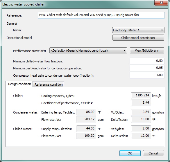
Water-cooled chillers
Reference
Enter a description of the component. Reference names should be informative with respect to differentiating similar equipment. It is for your use when selecting, organizing, and referencing any equipment within other component and controller dialogs and in the component browser tree. These references can be valuable in organizing and navigating the system and when the system model is later re-used on another project or passed on to another modeler.
Meter
Select the meter used by the chiller compressor to determine the category for reporting energy consumption results. This will be set to an energy source of Electricity for the electric chillers. It will be pre-set to “Cooling” as an energy end-use category (consistent with LEED EA credit 1 submittal requirements) when working with the pre-defined prototype ApacheHVAC systems, as provided by the Prototype Systems Library, System Prototypes & Sizing facility, or the ASHRAE 90.1 PRM workflow navigator.
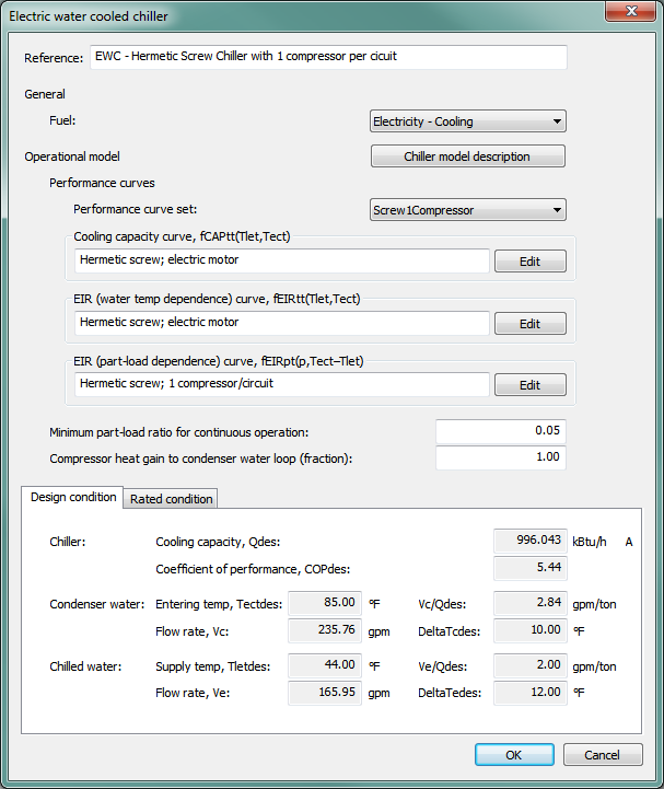
Figure 3 - 96 : Electric water-cooled chiller dialog
Chiller Performance
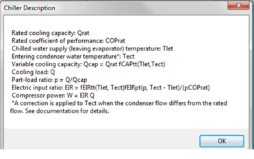
Chiller Model Description
Clicking this button provides a summary of electric water-cooled chiller model variables as shown below:
Figure 3 - 97 : Electric water-cooled chiller model description
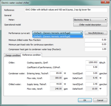
Figure 3 - 98 : Electric water-cooled chiller dialog showing drop-down selector for performance curve sets. Additional curve sets can be found using the View/Edit/Library button. The Reference condition tab will update according to the user selection.
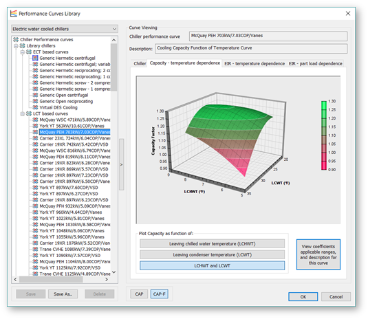
Performance Curve Library
The Performance Curves Library is the first of a set of tools for loading, visualizing, and customizing polynomial fit curve performance data for HVAC equipment. Initially, this covers a large number of generic (entering condenser temperature based) and actual (leaving condenser temperature based) electric water-cooled chiller models. It will later be expanded to include other HVAC plant equipment.
The n ew curves interface provide s exceptional visualization and access to curve parameters. Articulated 3D plot and two different 2D plots are provided for each of Capacity – temperature dependence, EIR – temperature dependence, and EIR – part-load dependence curves.
Figure 3 - 99 : Performance curves library showing a 3D plot of Capacity – temperature dependence for a model-specific LCT-based curve set
Understanding the performance curves for the electric water-cooled chiller model
The functions in each chiller curve set are structured according to industry-standard chiller modeling protocols and available curve sets. The following explanation is for the three biquadratic functions used to describe electric water-cooled chillers in the basic set of chiller curves included on the Performance curves selector.
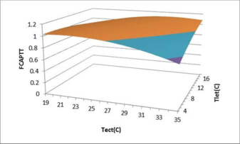
Cooling capacity: Qcap = Qrat fCAPtt(Tlet,Tect)
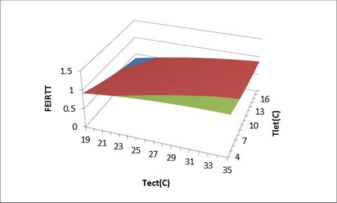
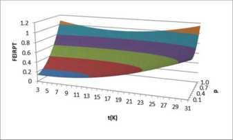
Electric input ratio: EIR = fEIRtt(Tlet, Tect) fEIRpt(p, Tect - Tlet)/(pCOPrat)
The variation in Capacity is a function of the temperatures of water leaving the evaporator (chilled water supply temperature) and entering the condenser. It is thus affected both by the temperature of water entering the condenser and the difference between the the temperatures of water leaving the evaporator and that entering the condenser.
-
Regardless of other parameters, the capacity of the chiller to reject heat will be diminished when it must reject this heat to warmer water.
-
The capacity of the chiller will also be affected by the amount of work it must do to “lift” thermal energy (i.e., as it really is a heat pump) out of the water at the leaving evaporator temperature and reject it to the much warmer water entering the condenser. The temperature difference or thermal lift across the chiller will vary both with reset of the chilled water supply temperature (evaporator leaving temperature) and the temperature of water delivered to the condenser from the cooling tower or fluid cooler in keeping with variation of outdoor climate conditions.
Electric input ratio (EIR) is a function of the part-load fraction, the temperatures for water leaving the evaporator and entering the condenser, and the difference between the the temperatures of water leaving the evaporator and that entering the condenser.
-
fEIRtt determines the EIR as a function of entering condenser water temperature and the difference between the entering condenser water temperature and leaving evaporator temperature (the same two independent variables as used to determine the capacity).
-
fEIRpt determines the EIR as a function of load fraction and the difference between the entering condenser water temperature and leaving evaporator temperature.
This temperature difference across the chiller affect the EIR because it is, as described above with respect to capacity, the thermal lift that the chiller must overcome. For any given load fraction, if the chiller is required to “lift” heat energy over a greater temperature difference from the relatively cooler water leaving evaporator to warmer water entering the condenser, this increased lift will require more electrical power to drive the compressor. Whereas the load will influence the flow rate of water through the evaporator and/or the return temperature entering the evaporator, thermal lift across the chiller will vary both with reset of the chilled water supply temperature and the temperature of water delivered to the condenser for heat rejection.
These functions describe three related 3D surfaces or performance maps, as shown below.
Figure 3 - 100 : Capacity as a function of the temperatures for water leaving the evaporator and entering the condenser.
Figure 3 - 101 : EIR as a function of the temperatures for water leaving the evaporator and entering the condenser.
Figure 3 - 102 : EIR as a function of the part-load fraction and the difference between the temperatures for water entering the condenser and leaving the evaporator.
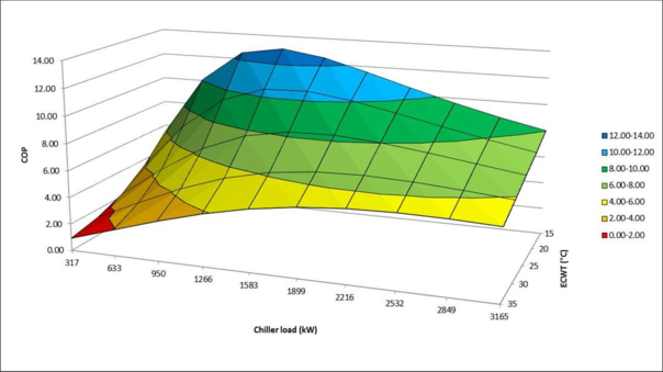
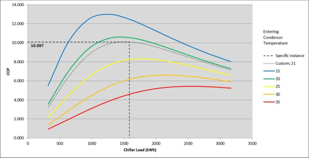
Figure 3 - 103 : Alternatively, one can graph overall COP and ECWT, as above. This plot and the next one below are for the same type of chiller (VSD Hermetic Centrifugal) as the preceding set of three graphs.
Figure 3 - 104 : A set of slices through this surface can be plotted as 2D curves, as below:
Cooling Capacity Curve, fCAPtt(Tlet,Tect)
This field indicates the currently selected performance curve for chiller capacity as a function of leaving evaporator temperature and entering condenser temperature for a particular chiller equipment type. Use the Select button to choose the appropriate curve from the system database.
Edit Cooling Capacity Curve, fCAPtt(Tlet,Tect)
The Edit button opens a dialog displaying the formula and parameters of the curve, allowing the curve parameters to be edited, if needed. However, this is recommended for advanced users only and requires both sufficient data from a manufacturer and an appropriate tool, such as MatLab, for generating the proper fit curve coefficients. For most users, selecting a representative curve for the chiller type and then entering appropriate performance characteristics (COP, cooling capacity, supply temperature, etc.) in the rated and design conditions tabs will be most appropriate.
When editing the curve parameters, it is important that you understand the meaning of the curve and its usage in the model algorithm. The edited curve should have reasonable ranges for the independent variables, as a given performance curve is only valid within its applicable ranges. If the independent variables are out of the set applicable ranges, the variable limits (maximum or minimum) specified in the input dialog will be applied.
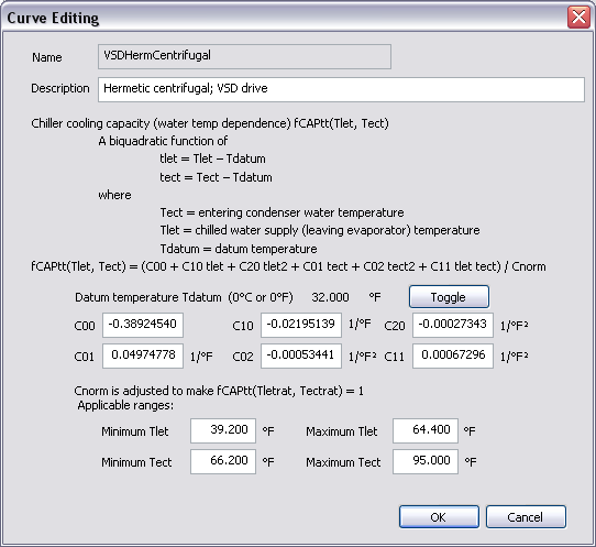
Figure 3 - 105 : Edit dialog for the cooling capacity curve of electric water-cooled chiller
The cooling capacity curve f CAPtt (T let, T ect ) is a bi-quadratic function of
tlet = Tlet – Tdatum
tect = Tect – Tdatum
where
T ect = entering condenser water temperature.
T let = chilled water supply (leaving evaporator) temperature.
T datum = datum temperature (0°C or 0°F), introduced for the convenience of units conversion of the curve coefficients.
And:
fCAPtt(Tlet, Tect) = (C00 + C10 tlet + C20 tlet 2 + C01 tect + C02 tect 2 + C11 tlet tect) / Cnorm
where
C 00 , C 10 , C 20 , C 01 , C 02 and C 11 are the curve coefficients
C norm is adjusted (by the program) to make f CAPtt (T letrat, T ectrat ) = 1
T ectrat = rated entering condenser water temperature.
T letrat = rated chilled water supply (leaving evaporator) temperature.
The cooling capacity curve is evaluated at each iteration of the chiller performance, for each time step during the simulation. The curve value is multiplied by the rated cooling capacity (Q rat ) to get the available (full-load) cooling capacity (Q cap ) of the current time step, for the specific T ect and T let temperatures:
Qcap = Qrat fCAPtt(Tlet,Tect)
The curve should have a value of 1.0 when the temperatures are at rated conditions.
EIR (Water Temp Dependence) Curve, fEIRtt(Tlet,Tect)
This field indicates the currently selected performance curve for chiller Electric Input Ratio (EIR) as a function of leaving evaporator temperature and entering condenser temperature for a particular chiller type. Use the Select button to choose the appropriate curve from the system database.
Edit EIR (Water Temp Dependence) Curve, fEIRtt(Tlet,Tect)
The Edit button opens a dialog displaying the formula and parameters of the curve, allowing the curve parameters to be edited, if needed. However, this is recommended for advanced users only and requires both sufficient data from a manufacturer and an appropriate tool, such as MatLab, for generating the proper fit curve coefficients. For most users, selecting a representative curve for the chiller type and then entering appropriate performance characteristics (COP, cooling capacity, supply temperature, etc.) in the rated and design conditions tabs will be most appropriate.
When editing the curve parameters, it is important that you understand the meaning of the curve and its usage in the model algorithm. The edited curve should have reasonable ranges for the independent variables, as a given performance curve is only valid within its applicable ranges. If the independent variables are out of the set applicable ranges, the variable limits (maximum or minimum) specified in the input dialog will be applied.
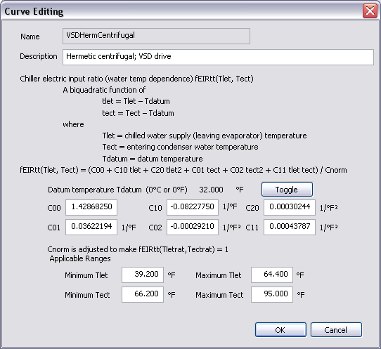
Figure 3 - 106 : Edit dialog for the EIR (water temperature dependence) curve of electric water cooled chiller
The chiller EIR (water temperature dependence) curve f EIRtt (T let, T ect ) is a bi-quadratic function of
tlet = Tlet – Tdatum
tect = Tect – Tdatum
where
T ect = entering condenser water temperature.
T let = chilled water supply (leaving evaporator) temperature.
T datum = datum temperature (0°C or 0°F), introduced for the convenience of units conversion of the curve coefficients.
And:
fEIRtt(Tlet, Tect) = (C00 + C10 tlet + C20 tlet 2 + C01 tect + C02 tect 2 + C11 tlet tect) / Cnorm
where
C 00 , C 10 , C 20 , C 01 , C 02 and C 11 are the curve coefficients
C norm is adjusted (by the program) to make f EIRtt (T letrat, T ectrat ) = 1
T ectrat = rated entering condenser water temperature.
T letrat = rated chilled water supply (leaving evaporator) temperature.
The chiller EIR (water temperature dependence) curve is evaluated for each iteration of the chiller performance, for each time step during the simulation. The curve value is multiplied by the rated EIR (= 1/ COP rat , where COP rat is the rated coefficient of performance) to get the full-load EIR of the current time step, for the specific T ect and T let temperatures. The curve should have a value of 1.0 when the temperatures are at rated conditions.
EIR (Part-load and water temperature dependence) curve, fEIRpt(p,Tect–Tlet)
This field indicates the chiller Electric Input Ratio (EIR) part-load dependence curve currently selected. This is the performance curve for chiller Electric Input Ratio (EIR) as a function of part-load fraction, entering condenser temperature, and leaving evaporator temperature for a particular chiller type. Use the Select button to choose the appropriate curve from the system database.
Edit EIR (Part-load and water temperature dependence) curve, fEIRpt(p,Tect–Tlet)
The Edit button opens a dialog displaying the formula and parameters of the curve, allowing the curve parameters to be edited, if needed. However, this is recommended for advanced users only and requires both sufficient data from a manufacturer and an appropriate tool, such as MatLab, for generating the proper fit curve coefficients. For most users, selecting a representative curve for the chiller type and then entering appropriate performance characteristics (COP, cooling capacity, supply temperature, etc.) in the rated and design conditions tabs will be most appropriate.
When editing the curve parameters, it is important that you understand the meaning of the curve and its usage in the model algorithm. The edited curve should have reasonable ranges for the independent variables, as a given performance curve is only valid within its applicable ranges. If the independent variables are out of the set applicable ranges, the variable limits (maximum or minimum) specified in the input dialog will be applied.
Figure 3 - 107 : Edit dialog for the EIR (part-load and water temperature dependence) curve of electric water-cooled chiller
The chiller EIR (part-load and water temperature dependence) curve f EIRpt (p,t) is a bi-quadratic function of
p = Q/Q cap
t = T ect –T let
where
p = part-load fraction
Q = cooling load
Q cap = available (full-load) cooling capacity
T ect = entering condenser water temperature.
T let = chilled water supply (leaving evaporator) temperature.
And:
f EIRpt (p,t) = (C 00 + C 10 p + C 20 p 2 + C 01 t + C 02 t 2 + C 11 p t) / C norm
where
C 00 , C 10 , C 20 , C 01 , C 02 and C 11 are the curve coefficients,
C norm is adjusted (by the program) to make f EIRpt (1 , T ectrat –T letrat ) = 1
T ectrat = rated entering condenser water temperature.
T letrat = rated chilled water supply (leaving evaporator) temperature.
The chiller EIR (part-load and water temperature dependence) curve is evaluated in each iteration of the chiller performance, for each time step during the simulation. The curve value is multiplied by the rated EIR (= 1/ COP rat , where COP rat is the rated coefficient of performance) and the EIR (water temperature dependence) curve value to get the EIR of the current time step, for the specific T ect and T let temperatures and the specific part load ratio at which the chiller is operating:
EIR = f EIRtt (T let ,T ect ) f EIRpt (p, T ect –T let ) / (pCOP rat )
The curve should have a value of 1.0 when the part load ratio equals 1.0 and the temperatures are at rated conditions.
A note on the applicable range of part-load ratio p:
The minimum p is used by the program as the minimum unloading ratio, where the chiller capacity can no longer be reduced by normal unloading mechanism and the chiller must be false loaded to meet smaller cooling loads. A typical false loading strategy is hot-gas bypass. If this is the false loading strategy used by the chiller, the minimum p is the part load ratio at which hot gas bypass starts.
The maximum p should usually be 1.0. During the simulation, a part-load ratio greater than 1.0 is a sign of chiller undersizing.
Minimum Part-load Ratio for Continuous Operation
This is the minimum part-load ratio at which the chiller can operate continuously. When the part-load ratio is below this point, the chiller will cycle on and off.
Compressor Heat Gain to Chilled Water Loop (fraction)
This is the fraction of compressor electric energy consumption that must be rejected by the condenser. Heat rejected by the chiller condenser includes the heat transferred in the evaporator plus a portion or all of the compressor energy consumption. For electric chillers with hermetic compressors, all compressor energy consumption is rejected by the condenser, so the compressor heat gain factor should be 1.0. For chillers with semi-hermetic or open compressors, only a portion of the compressor energy used is rejected by the condenser, so the compressor heat gain factor should be less than 1.0.
Rated Condition
‘Rated condition’ and ‘Design condition’ are provided for your flexibility in specifying chiller data.
The rated condition is the basis for the calculation of chiller characteristics at simulation time. The rated condition is usually the rated or ARI condition—i.e., the condition at which the chiller characteristics are specified by a manufacturer.
The default rated condition data are based on the standard ARI conditions (ARI Standard 550/590-2003): 44 o F leaving chilled-water temperature, 85 o F entering condenser water temperature, 2.4 gpm/ton evaporator water flow rate, 3.0 gpm/ton condenser water flow rate. Here ‘/ton’ means ‘per ton of refrigeration delivered to the chilled water’.
The design condition is the condition applying at the time of design peak chiller load.
A user wishing to use catalogue chiller data enters a capacity and COP at the rated condition and reads off the derived capacity and COP at the design condition.
A user wishing to size a chiller based on a design load enters a capacity and COP at the rated condition, then adjusts the capacity to produce the desired derived capacity at the design condition (allowing for a margin of over-sizing and differences between the rated and design temperatures, flow rates, etc.).
The derivations of chiller capacity and COP at design conditions and for each simulation time step (i.e., including off-design conditions) are done using the user-entered performance curves and other data.
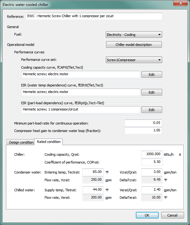
Figure 3 - 108 : Electric water-cooled chiller dialog showing Rated condition tab. The white fields in the Rated condition tab are edited to describe the performance of the chiller at the Rated condition.
Entering Condenser Water Temperature, Tectrat
When ‘Rated condition is design condition’ is ticked, the rated entering condenser water temperature is a dynamic copy of the design entering condenser water temperature. When ‘Rated condition is design condition’ is not ticked, enter the rated entering condenser water temperature.
Condenser Water Flow Rate, Vcrat, Vcrat/Qrat, ∆Tcrat
V crat , V crat /Q rat , and ∆T crat are three different options for specifying rated condenser water flow rate. Currently it is specified in terms of the ratio between rated condenser water flow rate (V crat ) and rated cooling capacity (Q rat ). The other two options (V crat and ∆T crat (the difference between the rated condenser water leaving and entering temperatures)) are automatically derived by the program based on the specified V crat /Q rat and cannot be edited.
When ‘Rated condition is design condition’ is ticked, the rated condenser water flow rate is a dynamic copy of the design condenser water flow rate. When ‘Rated condition is design condition’ is not ticked, enter the rated condenser water flow rate.
Chilled Water Supply Temperature, Tletrat
When ‘Rated condition is design condition’ is ticked, the rated chilled water supply temperature (leaving evaporator water temperature) is a dynamic copy of the design chilled water supply temperature. When ‘Rated condition is design condition’ is not ticked, enter the rated chilled water supply temperature.
Chilled Water Flow Rate, Verat, Verat/Qrat , ∆Terat
V erat , V erat /Q rat , and ∆T erat are three different options for specifying rated chilled water flow rate. Currently it is specified in terms of the ratio between rated chilled water flow rate (V erat ) and rated cooling capacity (Q rat ). The other two options (V erat and ∆T erat (the difference between the rated chilled water return and supply temperatures)) are automatically derived by the program based on the specified V erat /Q rat and cannot be edited.
When ‘Rated condition is design condition’ is ticked, the rated chilled water flow rate is a dynamic copy of the design chilled water flow rate. When ‘Rated condition is design condition’ is not ticked, enter the rated chilled water flow rate.
Cooling Capacity, Qrat
When ‘Rated condition is design condition’ is ticked, the rated cooling capacity is a dynamic copy of the design cooling capacity. When ‘Rated condition is design condition’ is not ticked, enter the rated cooling capacity.
Coefficient of Performance, COPrat
When ‘Rated condition is design condition’ is ticked, the rated coefficient of performance is a dynamic copy of the design coefficient of performance. When ‘Rated condition is design condition’ is not ticked, enter the rated coefficient of performance.
Design Condition
Figure 3 - 109 : Electric water-cooled chiller dialog showing design condition tab when “Rated condition is Design condition” tick box is ticked. When this is un-ticked, the inputs for Cooling capacity and COP are no longer edited here, but are editable in the Rated condition tab.
Entering Condenser Water Temperature, Tectdes
The design entering condenser water temperature is specified in the associated chilled water loop dialog (in the Heat rejection tab) and is displayed here as a derived parameter.
Condenser Water Flow Rate, Vc, Vc/Qdes, ∆Tcdes
V c , V c /Q des , and ∆T cdes represent three different possible means of specifying design condenser water flow rate. Currently, it is specified in terms of ∆T cdes (the difference between the design condenser water leaving and entering temperatures). This temperature difference is specified in the Heat rejection tab of associated chilled water loop dialog and the design condenser-water flow rate is then displayed in the chiller dialog as a derived parameter. As such, condenser-water flow rate (V c ) and the ratio between design condenser water flow rate (V c ) and design cooling capacity (Q des ) or V c /Q des are derived by the program based on the specified ∆T cdes and cannot be directly edited.
Chilled Water Supply Temperature, Tletdes
The design chilled water supply temperature (leaving evaporator water temperature) is specified in the associated chilled water loop dialog (in the Chilled water loop tab) and is displayed here as a derived parameter.
Chilled Water Flow Rate, Ve, Ve/Qdes, ∆Tedes
V e , V e /Q des and ∆T edes are three different options for specifying design chilled water flow rate. Currently it is specified in terms of ∆T edes (the difference between the design chilled water return and supply temperatures). It is specified in the associated chilled water loop dialog (in the Chilled water loop tab) and is displayed here as a derived parameter. The other two options (V e and V e /Q des (the ratio between design chilled water flow rate (V e ) and design cooling capacity (Q des ).) are automatically derived by the program based on the specified ∆T edes and cannot be edited.
Cooling Capacity, Qdes
When ‘Rated condition is design condition’ is not ticked, the design cooling capacity is automatically derived by the program using other design and rated condition data provided and does not need to be edited. When ‘Rated condition is design condition’ is ticked, enter the design cooling capacity.
This parameter is autosizable. When this parameter is autosized, its value in the field and its autosizing label ‘A’ become green.
Coefficient of Performance, COPdes
When ‘Rated condition is design condition’ is not ticked, the design coefficient of performance is automatically derived by the program using other design and rated condition data provided and does not need to be edited. When ‘Rated condition is design condition’ is ticked, enter the design coefficient of performance.