MicroFlo allows you to do internal CFD simulations of multiple rooms by connecting them. This allows the user to get a holistic view of the flow as it passes through multiple rooms. Typical examples include an apartment with different rooms connected via open door, remote exhaust locations etc.
The only pre-requisite for connecting rooms is that they have be connected to each other via ‘holes’. They cannot be connected by doors and/or windows only. The procedure to connect room is described in the sections below.
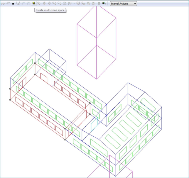
1. Select one of the rooms at model level of decomposition as a parent room. Typically this is a room which is connected to most other rooms when you are connecting multiple spaces. E.g. in the figure below the room on the north-west corner on ground floor connects to both the small room on north and L-shaped room on the east.
Figure 7-1: Selecting the parent room
Now, click on the ‘Create multi-zone space’ button on the MicroFlo toolbar.
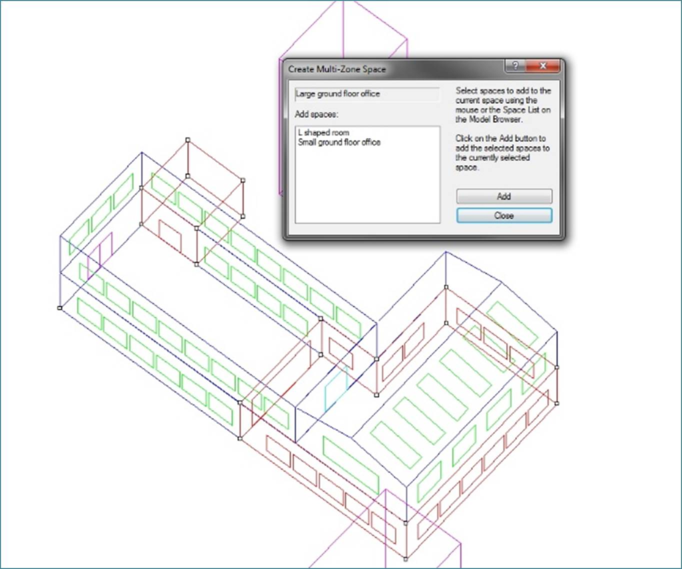
2. Select the rooms you want to connect to the parent room. These are designated as ‘Child Rooms’. You can either select and add them one at a time or select multiple rooms by using Ctrl+Click to add multiple rooms at the same time.
Figure 7-2: Selecting 'Child Rooms'
Once you have done selecting all the rooms click on ‘Add’ to create the multi-zone space. If you are done, click ‘Close’ to close the dialogue box or select more rooms to repeat procedure with other rooms.
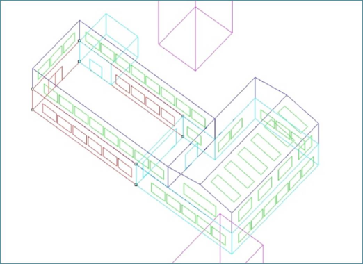
3. Once you have finished step 2, you will see that when you select the parent room at model level, the child rooms are also highlighted.
Figure 7-3: Child room highlighted when parent room selected
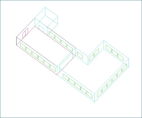
4. Now move down to the room level of the parent room. The child rooms will also appear along with the parent room.
Figure 7-4: Multi-zone space at room level
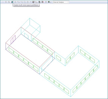
5. Now, click on the ‘Create Multi-zone space partitions’ button on the toolbar.
Figure 7-5: Create Multi-Zone space partitions: Before
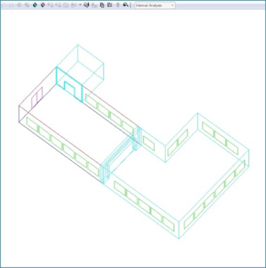
This will create thick partitions between zones. The thickness of the partitions is equal to the thickness of construction as specified for that wall in the DSM. This ensures that the cells in the CFD model do not overlap each other at the walls which are common to the two rooms.
Figure 7-6: Create Multi-zone space: After
6. Now that the multi-zone space is set up, you can proceed with adding boundary conditions as specified earlier. The boundary conditions for each room need to be added individually when being input manually. So to add boundary conditions in the children rooms, you will have to go back to model level and then down to room level of the child room to add the boundary conditions.
When you are looking at flow balance in the parent room, it will show you the sum of all the inlets and extracts across all the connected rooms. So you can have a supply diffuser in one room and extract diffuser in other room. The hole between the rooms will allow the air to flow between one rooms to another.
When boundary conditions are imported, you will only need to import them in the parent room. The boundary conditions for the connected rooms will be imported automatically. There is no need to import boundary conditions individually in such a case.
7. To delete the multi-zone space, follow steps in opposite order. First, when in parent room, click on ‘Destroy Multi-zone Space partitions’ to remove the partitions. Then move back to the model level and click on’ Separate multi-zone space’ to separate the rooms.