Importing Boundary Conditions from VistaPro Results
MicroFlo allows user to assign boundary conditions to the room(s) for an instance of VistaPro results automatically. This allows the user to look at how the flows are in detail for one instance of time.
Importing will bring in the following parameters automatically:
1) All surface (wall, window, door and hole) temperatures.
2) Flows through MacroFlo openings (optional)
3) Convective component of the internal gains specified in the room template of ApacheSim. (optional)
4) The rate of generation of H2O and CO2 within the domain due to internal gains.
Importing will NOT bring in the following:
1) Flows due to infiltration
2) Flows due to any other air exchanges specified
3) Flows due to ApHVAC components
The boundary conditions’ file can be read to understand the amount of heating or cooling required for the particular room, but this data will not be imported automatically.
Preparing for Import of Boundary Conditions
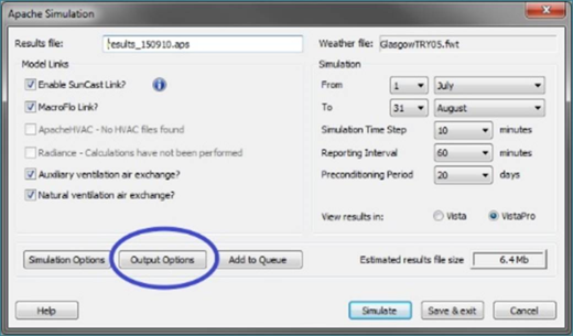
Before you are able to import the boundary conditions, you have to make sure the Apache Simulation is setup correctly to export the boundary conditions. This can be done easily in the ApacheSim dialogue box. Before you run Apache Sim, open the output options.
Figure 8-1: Apache Simulation Dialogue
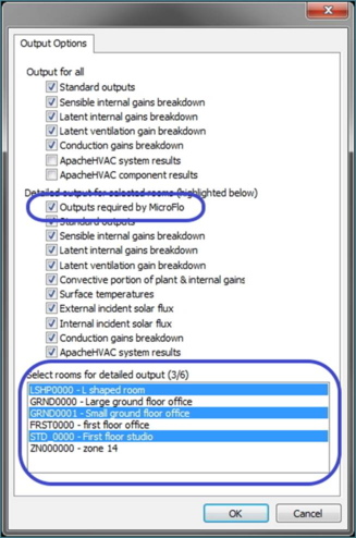
Figure 8-2: Output Options
In this dialogue, make sure you have selected the ‘Outputs required by MicroFlo’ option. In the list at the bottom, ensure that you have selected all the rooms that you want the boundary conditions exported for after running the Apache Simulation. You can select multiple rooms by holding Ctrl and clicking on various rooms in the list. Please note that boundary conditions will NOT be exported for the rooms which are not selected in the list. Click OK to close this dialogue box after you have set everything as per requirements and/or choice. Run the ApacheSim now.
After running Apache Sim, the results will open in Vista/VistaPro as per the choice selected. Once you have analysed the results and selected an occasion to export the results, go to ‘Menu -> Vista/VistaPro -> Export Boundary Conditions’.
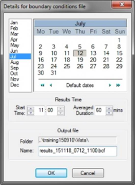
This will bring up the dialogue box shown in figure 8-3 below. Select the appropriate date and time for instance of results. Ensure that the ‘Averaged Duration’ is greater than or equal to the ‘Reporting Interval’ seen in ApacheSim dialogue in figure 8-1. Choose an appropriate file name with ’.bcf’ as the extension. Click Ok to complete the export of boundary conditions. Click Cancel if you want to abort the export.
Note that you will need to create a separate file for each instance of results you want to look at in detail.
Figure 8-3: Boundary conditions export dialogue
This file will be placed in the ‘Vista’ folder of the project folder.
Importing the Boundary Conditions
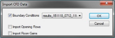
After you are done exporting the boundary conditions to the file, switch to the MicroFlo application. Navigate to the room level of the room you want to import the boundary conditions for. If it is a multi-zone space, navigate to the room level of the parent room of that multi-zone space. Click on ‘Import Boundary Data’ button on the MicroFlo toolbar or go to ‘Menu -> MicroFlo ->Import Boundary Data’. This will bring up the dialogue box which will initially look like in figure 8-4.
Figure 8-4: Import CFD data: Initial view
Boundary Conditions
This is a mandatory option for the dialogue. Otherwise the dialogue will not do anything. This option will bring in the temperatures of various surfaces within the domain. For wall/ceilings/floors with external adjacency, the temperature will be applied as surface temperature as explained in figure 3-10. For all others i.e. windows, doors, holes and walls with internal adjacency, the temperature is applied as a temperature boundary condition.
Import Opening Flows
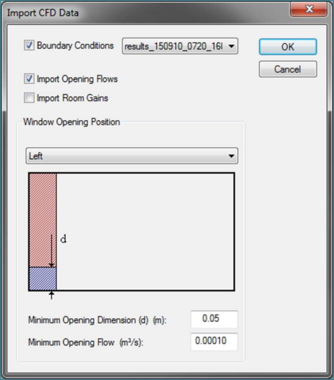
This option allows you to select if you want to automatically include the MacroFlo openings in the MicroFlo analysis. Clicking this option expands the ‘Import CFD Data’ dialogue as in figure 8-5.
Figure 8-5: Import Opening flows
The openings are imported in the following manner:
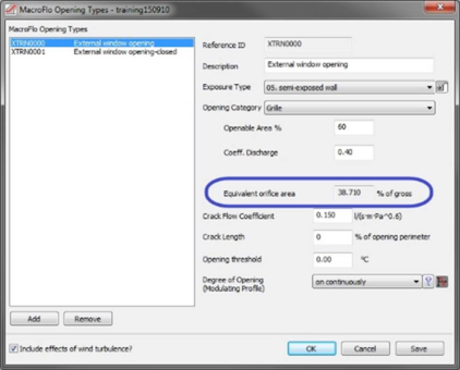
1) Each opening is divided into two parts – flow region and non-flow region. The area of the flow region is equal to the equivalent orifice area of that opening as defined in MacroFlo.
Figure 8-6: Equivalent Orifice opening
2) The rest of the opening is blanked off to form the non-flow region. This region will be applied a temperature boundary condition as per the exported VistaPro results. If the opening has 100% equivalent orifice area, then there will be no non-flow region of the boundary.
3) The flow area then could be treated further based on the nature of the opening. If the VistaPro results indicate that the opening has unidirectional flow, then the rest of the opening will be applied either a ‘General Supply Diffuser’ boundary condition or an ‘Extract’ boundary condition depending on the direction of the flow at the opening. For the supply diffuser, the inputs with regards to the property of air (temperature, humidity, CO2 and CO will be equal to the levels on the other side of the opening. If the opening connects to the outside, the conditions will be ambient. If the opening is internal, the properties will be based on conditions on the adjacent room.
4) If the VistaPro results predict the opening to have a flow in both directions – in and out of the domain, the flow region will be divided into two parts whose areas will be directly proportional to the flowrates in each direction. As before, the inlet to the domain will be general supply diffuser with properties as described in point 3 above. The outlet from the domain will be an extract diffuser. Whichever opening is expected to have airflow at a higher temperature will be placed in the higher position. E.g. if the room temperature predicted is 23oC and the ambient is 30oC, the extract boundary will be placed under the supply boundary.
There are three options for ‘Importing the Flows’
1) Window Opening Position: This will determine the side on which the flow region will be placed on the opening. This position is based on looking at the opening at the surface level of decomposition for that surface.
2) Minimum Opening Dimension (m): The flow opening will not be imported if any of the dimensions of the flow boundary condition are less than the number noted here. This also means the flow associated with the opening is not imported and could lead to flow imbalance.
3) Minimum Opening Flow (l/s): As above, the opening will not be imported if the flowrate through the opening falls below this threshold. Again, if this value is set to too high, it could lead to flow imbalance.
Flow imbalance may occur in following cases:
1) The room has an HVAC supply /extract and the make-up air is accounted for by a MacroFlo opening. Since MicroFlo only imports MacroFlo opening, there may be a unidirectional flow boundary imported without a corresponding extract or supply. In this case, the HVAC supply or extract has to be added manually. The VistaPro results may have be queries for determining the properties of the general supply diffuser that is based on HVAC supply.
2) There are non-rectangular openings. MicroFlo only draws rectangular supply/extract diffuser boundaries for non-rectangular openings. It may happen that such boundaries overlap with other boundaries and may not get drawn and cause imbalance.
3) You have imported boundary conditions before you have completed the creation of the multi-zone space and partitions.
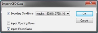
Import Room Gains
This option allows you to automatically include the convective component of the room internal gains in the MicroFlo analysis. Clicking the option looks as in figure 8.7
Figure 8-7: Import Room Gains
The room gains are imported in the following manner.
1) Each internal gain is divided into a convective component and a radiative component. This division is based on the inputs provided for the internal gains in respective template.
2) The radiative component is applied as a temperature correction on the walls. This leads to a slight increase in wall temperature. Thus the radiative component is added to the simulation indirectly.
3) The convective component of the gains is available for the user to apply. If not applied manually, this will be applied as a diffuse source of heat throughout the room.
4) In addition to the heat gains, the rate of generation of water vapour and CO2, calculated on basis of the latent gains in that rooms, are also imported. These are also applied as diffuse source throughout the space.
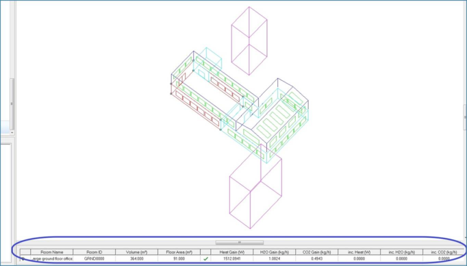
The summary of the gains can be seen in the room properties at model level. It shows the details for that particular room.
Figure 8-8: Gains import status
The green tick mark shows the gains’ import is active. It can deactivated by double clicking on the green tick mark to change it to a red cross. Now the gains’ import is turned off. This does not affect boundary conditions.
For MicroFlo, any heat adding boundary or a heat source is a heat gain. It may represent a heater or a person. When the green tick mark is ON, the maximum heat gains that you can add is equal to the total heat gain as seen in the figure. If you exceed the number, MicroFlo will automatically add a cooling effect to counter this additional gain. If you do not want MicroFlo to counter the gain, you can set the green tick mark to a red cross as described. Now there is no limit to the gains that can be applied.
Boundary Condition File
The boundary condition file can be found in the Vista folder inside the project folder. This file can be opened in a text editor/spreadsheet tool to view the exported data. We recommend that you do not edit the file manually. The file has the following sections as explained below
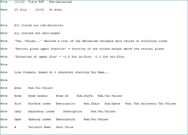
Header
The file header looks like in
Figure 8-9: Boundary Condition File header
This is just the header section which details out how the information has been listed in the file. At the top it lists the file type which is ‘Vista BCF’. This followed on next line by the instance for which boundary conditions were exported and the duration used for averaging of the VistaPro results for the export.
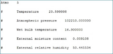
Atmospheric Data
Figure 8-10: Boundary Condition File: Atmospheric data
This section lists the atmospheric data for the external conditions for the instance of export of boundary conditions.
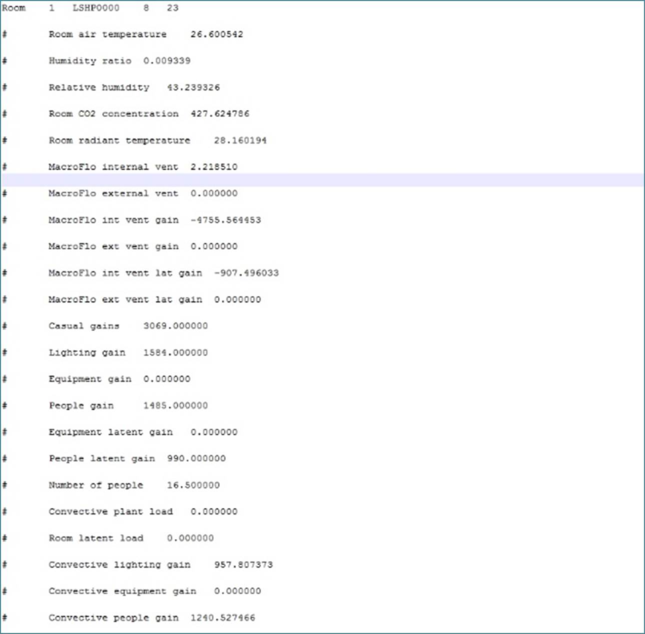
Space Data
Figure 8-11: Boundary Condition File: Space Data
This lists out the results for the room. This is the basis of the data imported into MicroFlo simulation. A particular point of interest is the ‘Convective Plant Load’. In case you have imported your results from the results of the ApacheSim where the room has a set point, ‘Convective plant Load’ will be the heating and cooling that will have to be applied to the CFD model to achieve the same average temperature results as the ‘Room Air Temperature’ noted here.
As a thing to watch out for: If you import room gains and apply this heating or cooling, MicroFlo will try to compensate for the increase or decrease in gains applied. To counter this, set the green tick mark seen in figure 8-8 to a red cross and then apply the gains and heating or cooling.
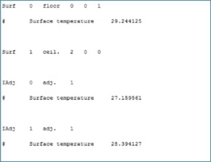
Surface data
Figure 8-12: Boundary Condition File: Surface data
This part lists out the details of the surface temperatures being imported. For the surfaces which have no adjacency, the single value of surface temperature is noted. For surfaces with adjacency, temperature of each adjacency is noted individually.
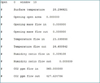
Opening data
This notes the data for openings like windows, doors and holes. The surface temperature is the temperature applied to the non-flow surface of the opening as seen in
section 8.2.2. In case the flows through the opening are zero, the opening will only have the surface temperature assigned to it.
This is particularly useful in case of imbalance of flow occurring due to shape of the openings as explained in
section 8.2.2. If there is imbalance showing up due to this, you can confirm it by going through the list of openings for that room and cross checking if all openings have been included. If one or more are excluded, you can go ahead and make suitable changes to the original model or add the missing flow boundaries manually.