This section looks at functions associated with the Model toolbar. We shall describe only those options which differ from ModelIT.
Draw Extruded Shape
(“Draw” Þ “Extruded Shape”)
Pops-up the following window:
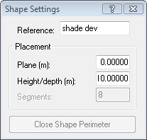
Selecting this command allows you to create an extruded shape as a series of straight-line segments. Select each point of the shape in turn, in either clockwise or anti-clockwise order. To close the shape, click on the “Close Shape” button which is active while you are drawing the shape. If you make a mistake and need to undo a point, click on the right mouse button. The current lock settings will apply and key-in values can also be used. The extruded shape will be created with the defined Plane (m) and Depth (m) values as currently set in the Shape Settings dialogue box. An extruded shape can be created along any axis.
Note that you cannot cross a segment with another segment and you cannot place a perimeter point on an existing perimeter point unless it is the first point in which case this will close the shape.
The relevant key-ins for the extruded shape are: x=<x, y>, dx=<dx, dy> and p=<length, angle>.
Draw Plane
(“Draw” Þ “Plane”)
Pops-up the following window:
Creates a plane at the given height. This function is not available in ModelIT.
The relevant key-ins for the prism are: x=<x, y>, dx=<dx, dy> and p=<length, angle>.
Draw Prism
(“Draw” Þ “Prism”)
Pops-up the following window:
Selecting this command allows you to create a prism shape. Select the point where one corner of the prism is to be located, then select the point that is at the opposite corner of the prism. A new prism will then be created with the defined Plane (m) and Depth (m) values as currently set in the Shape Settings dialogue box. A prism can be created along any axis.
The relevant key-ins for the prism are: x=<x, y>, dx=<dx, dy> and p=<length, angle>.
Draw Pyramid
(“Draw” Þ “Pyramid”)
Pyramids are created in a very similar way to extruded shapes except that after completing the perimeter, you will enter a point to define the apex of the pyramid.
Pops-up the following window:
Selecting this command allows you to create a pyramid shape. To create pyramids, you must first define the shape of the base of the pyramid and then position the top of the pyramid. To define the pyramid base, select each point on the perimeter of the base in turn, in either clockwise or anti-clockwise order. To close the shape, click on the "Close Shape" button on the Shape Settings dialogue box which is active while you are drawing the shape. Next, select the position of the top of the pyramid. A new pyramid will be created with the base at the defined Plane (m) value as currently set, and the top point at the Plane + Depth (m) values as currently set. A pyramid can be created along any axis.
The relevant key-ins for the pyramid are: x=<x, y>, dx=<dx, dy> and p=<length, angle>.
Draw Sphere
(“Draw” Þ “Sphere”)
Pops-up the following window:
Selecting this command allows you to create a spherical shape. To create a sphere, first select the centre of the sphere and then select a point which defines the radius of the sphere. A new sphere will be created with its centre at the defined Plane (m) level that is currently set in the Shape Settings dialogue box which is active while you are drawing the shape. The number of chord segments which make up the sphere is defined in the Shape Settings dialogue box. A sphere can be created along any axis.
The relevant key-ins for the sphere are: x=<x, y>, dx=<dx, dy> and p=<length, angle>.
Draw Hemisphere
(“Draw” Þ “Hemisphere”)
Hemispheres are created in exactly the same way as spheres.
Pops-up the following window:
Selecting this command allows you to create a hemispherical shape. To create a hemisphere, first select the centre of the hemisphere and then select a point which defines the radius of the hemisphere. A new hemisphere will be created with its base at the defined Plane (m) level that is currently set in the Shape Settings dialogue box which is active while you are drawing the shape. The number of chord segments which make up the hemisphere is defined in the Shape Settings dialogue box. A hemisphere can be created along any axis.
The relevant key-ins for the hemisphere are: x=<x, y>, dx=<dx, dy> and p=<length, angle>.
Draw Cylinder
(“Draw” Þ “Cylinder”)
Cylinders are created in a similar way to spheres and hemispheres.
Pops-up the following window:
Selecting this command allows you to create a cylindrical shape. To create a cylinder, first select the centre of the cylinder and then select a point that defines the radius of the cylinder. A new object will be created with the defined Plane (m) and Height/Depth (m) at the values currently set in the Shape Settings dialogue box which is active while you are drawing the shape. The number of chord segments which make up the cylinder is defined in the Shape Settings dialogue box. A cylinder can be created along any axis.
The relevant key-ins for the cylinder are: x=<x, y>, dx=<dx, dy> and p=<length, angle>.
Component Handle
This sets the “handle” point of the component.
Note: the option to move the component handle is no longer supported in Component Modeller, the default handle used in <VE> when placing any component is at the origin point (0,0,0).
Component Viewer
Pops-up the following window:
For details of how to use the functions in the component viewer please refer to the
ModelIT User Guide.