Background
MicroFlo is the CFD analysis tool within the IES <Virtual Environment> suite of tools. Some of the features of MicroFlo are as follows:
· It is based on ‘Finite Volume Method’ of discretisation of the partial differential equations that describe the fluid flow.
· The formulation uses steady state three dimensional convection-condition heat transfer and flow model.
· The ‘SIMPLE’ algorithm is used to achieve the coupling between pressure and velocity fields.
· Turbulence models are available
· MicroFlo uses wall functions to calculate near-wall properties of turbulence as well as flux of heat and momentum.
· There is no direct radiation model within MicroFlo. The effects of radiation can however be modelled when boundary conditions are imported from VistaPro.
· MicroFlo features a structured non-uniform Cartesian grid.
MicroFlo is an ad-hoc CFD tool. As such it cannot read data directly from the templates, constructions, systems and profiles that have been setup. The only way it can read the data related to gains is when the boundary conditions are exported from VistaPro and imported into MicroFlo. Any changes/additions made to the model in MicroFlo will not be reflected in the results of the ApacheSim run.
Types of Simulations
There are two types of CFD simulations available in MicroFlo.
1. Internal
As name suggest, the domain for these simulations lies inside one or many connected rooms. This type of simulations supports modelling of both flow and heat transfer. It is possible to add boundary conditions on the room surfaces. The user can insert components to act as solids or sources of quantities. The user is also able to import the boundary conditions from the results of Apache Simulation.
2. External
The external CFD simulation allows for analysis of flow over the buildings. This type of simulation is isothermal in nature and does not allow for modelling of heat transfer. This simulation is purely a flow only simulation. The only user inputs are direction of wind. Wind speed and size of domain.
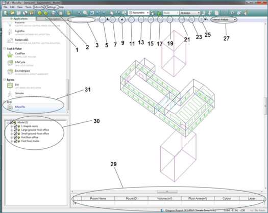
MicroFlo Window
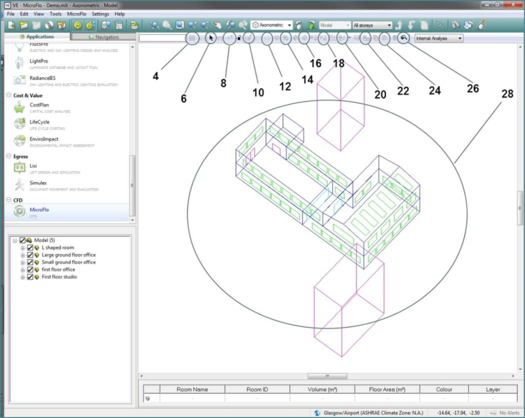
Figures 2-1 and 2-2 below highlight the different parts of the MicroFlo window. The MicroFlo is listed under the CFD applications.
Figure 2-1: MicroFlo Window – Parts
Figure 2-2: MicroFlo Window – Parts
Description of parts:
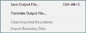
1. MicroFlo Menu
Figure 2-3: MicroFlo Menu
a. Save Output File…: Save the results of the CFD simulations to a file
b. Translate Output File…:This enables user to translate the CFD output file from version of VE including and before 5.9 to the current version
c. Clear Imported Boundaries: This will clear any boundary conditions that were imported (available at room level)
d. Import Boundary Data: To import the boundary conditions from the boundary condition file (available at room level)
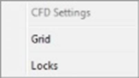
2. Settings
Figure 2-4: Settings Menu
a. CFD Settings: Opens the CFD settings Dialog box ((available at room level)
b. Grid: Opens dialog to adjust the grid size
c. Locks: Opens the dialog to select the cursor movement locks
3. Key-in command line
4. Grid settings: Opens dialog to adjust the grid size
5. Set grid alignment: align the grid to suit the model
6. Select object: closes any mode and switches to default pointer
7. Measure length: measure length between two points
8. Query cell values (not available in new versions of VE (>5.9) and permanently disabled
9. Locks: Opens the dialog to select the cursor movement locks
10. Draw Arc: draw an arc for construction line
11. Draw Construction Line
12. Remove All Construction Lines
13. Create Multi-zone space: to join multiple rooms to create a CFD domain (available when a room is selected at model level)
14. Separate Multi-zone space: to separate the multi-zone space created as per previous command (available when the parent room of a multi-zone space is selected at model level)
15. Create Multi-zone space partition: create a partition equal to the total thickness as mentioned in the construction of the wall in DSM
16. Destroy Multi-zone space partition: remove the partition created in previous step.
17. Copy Selection Set: Copy the selected – boundary conditions, components etc.
18. Move Selection Set: Move the selected – boundary conditions, components etc.
19. Rotate Selection Set: Rotate the selected – boundary conditions, components etc.
20. Add Boundary conditions: Opens the dialog box for adding boundary conditions (available at surface level in boundary mode)
21. Import Boundary data: Opens dialog box to import boundary conditions from a boundary condition file
22. Place Component: Opens dialog box to manipulate and place component ((available at room level)
23. Settings: Opens the CFD settings dialog box (available at room level)
24. Run: Runs the simulation
25. Delete: Delete selected – boundary conditions, components etc.
26. MicroFlo Viewer: Opens the MicroFlo Viewer to see results of the simulation after simulation has been run.
27. Drop down box to toggle between Internal and External simulation mode
28. Model Space
29. Object properties: This part shows the various properties of the selected entity – could be room, surface, boundary condition, component etc.
30. Model Browser for MicroFlo: Note that room groupings used in the other applications are not available in MicroFlo.
31. Location of ‘MicroFlo’ application in the list of applications.