External CFD simulation enables the user to analyse the flow around the buildings. Characteristics of external simulation in MicroFlo are as follows:
1) The simulation is isothermal
2) All external openings are assumed to be closed – there is no interaction between internal and externa air.
3) In MicroFlo external simulation, the north is always in the positive Y direction irrespective of the site rotation set in ModelIt.
4) It does not read in any weather data.
5) There are no user applied boundary conditions or components for external simulation.
The only things that need to be setup are the orientation of the model, CFD grid and the wind speed before you run the simulation.
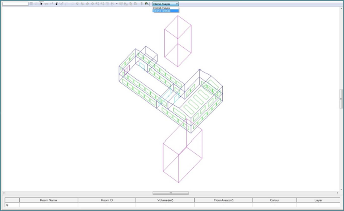
To switch from the internal simulation to external simulation, click on the drop down box on MicroFlo toolbar at model level of decomposition.
Figure 9-1: Switch from internal to external simulation
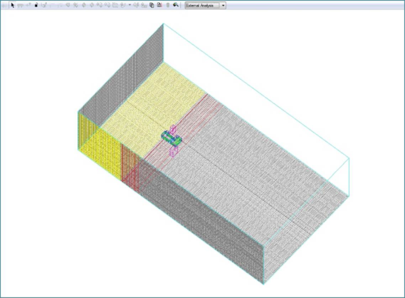
This will immediately switch to a grid view.
Figure 9-2: External Simulation view
After this, all the set-up is done through the CFD settings dialogue brought up by clicking the ‘CFD Settings’ (

) button on the MicroFlo toolbar
Wind
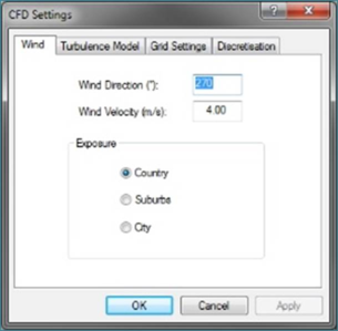
This tab on the CFD Settings dialogue lets you input all the settings related to the wind.
Figure 9-3: CFD Settings: Wind
1. Wind Direction (o): This is the direction from where the wind will be coming from. It is measured as degrees east of north. You will find that the model rotates while the grid is fixed as you change this number.
2. Wind Velocity (m/s): Input the meteorological wind velocity that you want to consider for the analysis.
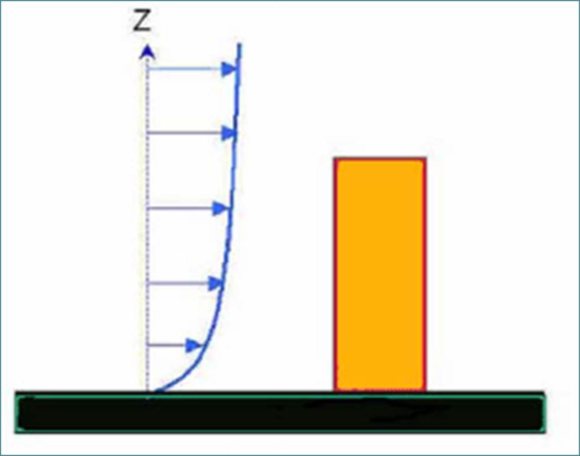
3. Exposure: This option determines the shape of the wind boundary layer. The typical shape of the wind boundary profile is shown in figure 9-4 below.
Figure 9-4: Typical velocity profile of an atmospheric boundary layer
The wind speed UH at height H above the ground is given by:
Where,
a = Exponent in power law wind speed profile for local building terrain
δ = fully developed strong wind atmospheric boundary layer thickness (m)
amet = Exponent for the meteorological station
δmet = Atmospheric boundary thickness at the meteorological station (m)
Hmet = Height at which meteorological wind speed was measured (m)
Umet = Hourly meteorological wind speed, measured at height Hmet (m/s)
The exposure types and related parameters can be described as follows:
|
Terrain Type
|
Description
|
Exponent a
|
Layer Thickness δ (m)
|
|
Country
|
Open terrain with scattered obstructions having heights generally less than 10 m, including flat open country typical of meteorological station surroundings
|
0.14
|
270
|
|
Suburbs
|
Urban and suburban areas, wooded areas, or other terrain with numerous closely spaced obstructions having the size of single-family dwellings or larger, over a distance of at least 2000 m or 10 times the height of the structure upwind, whichever is greater
|
0.22
|
370
|
|
City
|
Large city centres, in which at least 50% of buildings are higher than 21m, over a distance of at least 2000 m or 10 times the height of the structure upwind, whichever is greater
|
0.33
|
460
|
The meteorological data is always assumed to have been captured on a ‘Country’ type terrain.
Grid Settings
This tab on the CFD Settings dialogue lets you input all the settings related to the grid.
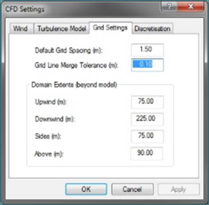
Figure 9-5: CFD Settings: Grid Settings
1. Default Grid Spacing (m): This is same as the setting as explained in
section 5.4.
2. Grid Line Merge Tolerance (m): This is same as the setting as explained in
section 5.4
3. Domain Extents (beyond model): For external simulations, the grid around the model has to be large enough to accommodate any of the large fluid structures that can be created in the wake of the model and the also ensure that the boundaries other than the ground do not have an effect on the results. The extents noted here are beyond the bounding box of the entire model including any adjacent building and other external paraphernalia added to the model. Typical recommendation are as follows:
a. Upwind: This should be at least 5 times the height of the tallest object (building or otherwise) present in the model.
b. Downwind: This should be at least 15 times the height of the tallest object (building or otherwise) present in the model.
c. Sides: This should be at least 5 times the height of the tallest object (building or otherwise) present in the model.
d. Above: This should be at least 5 times the height of the tallest object (building or otherwise) present in the model.
Turbulence Model
Discretisation