HVAC Systems & Other Inputs
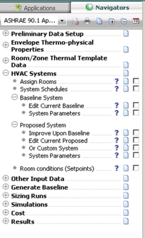
Figure 39 - HVAC Systems Sub-categories and Tasks
This navigator category consists of a number of sub-categories and tasks designed to guide users through the process of setting up the baseline & proposed HVAC systems.
Set up Room Grouping for HVAC Assignment
Once a predefined system or systems has been loaded or a custom system created in ApacheHVAC, all conditioned rooms, HVAC zones, supply plenums (if any), and return plenums (if any) must be assigned to the HVAC network. If not, they will be conditioned instead by a simplified method in Apache Systems—within the Apache Thermal view. While Apache Systems is appropriate for early schematic design and for compliance with certain standards, more detailed ApacheHVAC systems should be used for comparative analysis of design and control strategies, supporting design decisions, and documenting projected energy performance and must be used for the ASHRAE 90.1 Performance Rating Method. If there are unconditioned spaces in the building, they should have the HVAC System selection on the System tab in the associated room thermal template or Space Data set to “None”. As such, if they are not assigned to an ApacheHVAC system, they will not be conditioned.
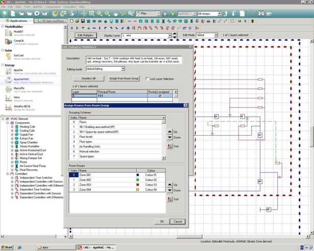
While rooms or zones can be individually added to new layers in the multiplexed HVAC network, for all but very small projects with few rooms it is far more efficient to assign the rooms/zones from room groups. To do so, click once anywhere in the multiplexed region dashed green line) to select it and then click the Edit Multiplex button. The Assign from room group button allows entire groups of rooms to be assigned to the selected ApacheHVAC network. This will automatically add more layers as needed; however, if subsequently assigning rooms from additional groups, be aware that the last layer on the list of Layer and Principle Rooms must first be selected and this layer will be assigned to the first room/zone in the group.
All rooms or zones should be organized in groups using an appropriate grouping scheme, such as one group per air handler or similar, prior to assigning rooms in ApacheHVAC.
System Schedules
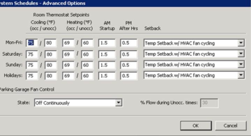
Set ApHVAC system operation schedules. Indicate the occupied and unoccupied hours and the associated heating and cooling set points. The morning start-up and after-hours operation are in relation to the occupied hours. Select the appropriate control strategy for operation using setback temperatures during the unoccupied hours. These settings will apply to all ApacheHVAC systems for this project that use the default control (HVAC HP1, HP2, CP3, CP6, etc.) profiles referenced in the prototype baseline system controllers. These inputs are important for the unmet load hour check as they essentially set the heating & cooling system schedules/set point temperatures
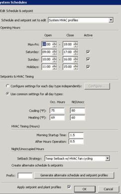
Any number of additional HVAC schedules can be created to match any building system operation schedule or set point where zones may have different requirements. This is done by entering a “Prefix” refer in the dialogue & clicking the “generate alternative schedule & set points”. For example if a prefix refer of “0823” is entered & generate is clicked a copy of the default HVAC control profiles will be created in ApPdbm with prefix of “0823” at the start of all control profiles. Alternative profiles can be selected for global assignment via the “schedule & set point” dropdown at the top of the schedule dialogue, the “Apply set point & plant profiles” tick box must be activated for assignment to happen once the OK is clicked in the main dialogue. If a model uses varying operation schedules these profiles must be assigned manually to ApHVAC systems in later workflows.
Advanced schedules can also be setup via the “Configure” tab in the main dialogue this feature allows users to setup more detailed system schedules. See below image;
Baseline system
Setup Baseline system configuration for system sizing runs
Edit Current Baseline
Users are presented with the ten ASHRAE 90.1 baseline HVAC systems, which correspond to System 1-8(10) listed within Table G3.1.1A and Table G3.1.1B (2007 & 2010). Users must identify which baseline system is required to be modeled for the project in question based on the ‘building type’ (type and area) and whether the energy source is a combined approach (fossil fuel, electric, hybrid, etc) or ‘electric or other’, which are outlined in the tables mentioned above. Once the system type is identified users select & import the system(s) on to the ApHVAC work space. A number of system loops will need to be imported depending on the system design in question. Prototype systems can be imported in a vertical or horizontal placement. The auto placement automatically arranges HVAC systems in a tidy fashion on the work space.
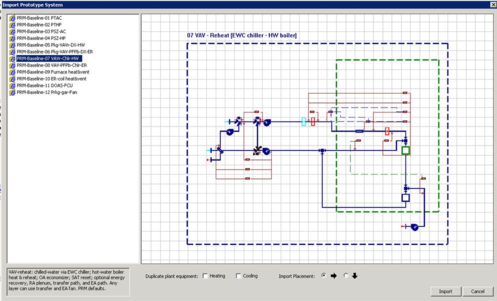
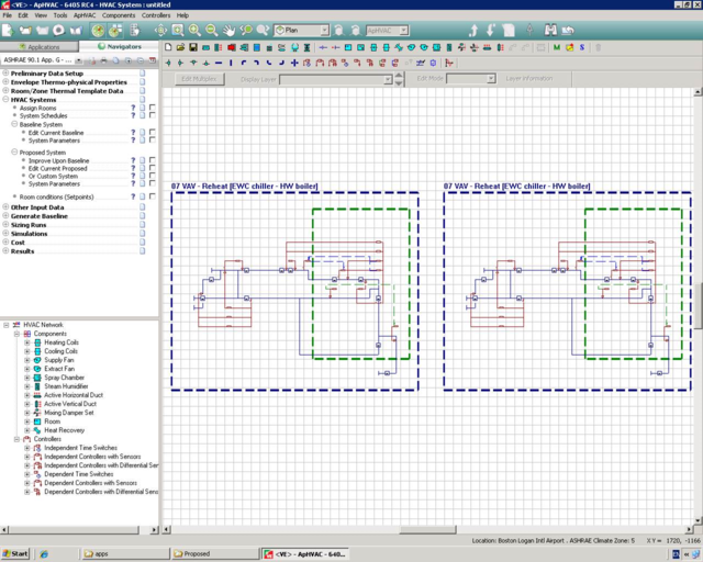
The above image is the “Import prototype system” dialogue. This dialogue can be re-activated by clicking the “Import prototype type system” button in the main ApHVAC tool bar. If I re-activate this dialogue multiple system loops can be imported in the ApHVAC work space, see below image with two system 7 loops imported;
Once the systems have been layout in the required configuration on the ApHVAC work space baseline HVAC networks should be renamed & organized accordingly. Selecting the “S” icon & double clicking any ApHVAC baseline network will allow users rename HVAC networks.
HVAC grouping scheme must be assigned to the ApHVAC networks these grouping schemes should have been created in the “Assign rooms” workflow action. Double clicking the Multiplex & using the “Assign from room group” icon allows groups of rooms to be assigned to the selected ApHVAC network.
See ApHVAC user guide for further information on Multiplexing & the group assignment feature.
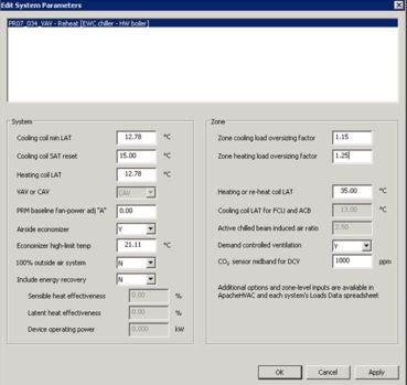
System Parameters
Select the HVAC network(s) from within the white dialogue box & set the below system information, click “Apply” & “OK”. This information is critical to the baseline sizing runs. Energy recovery & air side economizer rules must be manually applied using the system parameters dialogue as per the ASHRAE 90.1 section 6 & Appendix G. Certain inputs will be grayed out where inputs are not applicable to the selected prototype system in question.
Varying system information can be assigned to individual & multiple system types, once the information is set OK can be clicked & all information will be applied accordingly.
Proposed System
Users have the option to create the proposed HVAC network by copying and editing the existing baseline HVAC network or by creating a new HVAC network from scratch or using one of the prototype systems.
Improve Upon Baseline
Users are presented with the option to use the Baseline system as the proposed system. Edits can be made to the baseline system & then saved as the proposed system. This is a useful feature for early stage PRM modelling.
Clicking this link in the navigator is the same as clicking “save as” while having the baseline network open and saving it as “proposed.asp”.
Edit Current Proposed
Edits can be made to the copied baseline HVAC system & saved as the proposed system. For early stage analysis where the system may not be know this is a useful option for assessing the affects of introduction generic system optimization strategies for example;
· Energy recovery
· Air side economizer
· Water side economizer
· High efficiency plant
· VSD pumps
· High efficiency fans
· Etc
OR Custom System
Opens a new blank HVAC work space so that users can create a proposed HVAC network from scratch or select one of the pre-defined prototype systems. All prototype systems can be auto sized & customized to match the proposed HVAC system design. Auto sizing the proposed system will only be applicable for early stage analysis as the proposed system must represent the actual system design in order to accurately assess the quality of the HVAC design. Modifying the proposed network to represent the actual system design would involve creating the actual plant components as per there type & capacity, inputting actual design air side flow rates & setting up all auxiliary system components as per there design (fans & pumps etc).
AHU System Parameters
As per baseline “AHU system parameters” assignment
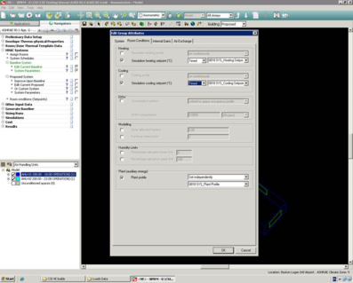
Room conditions (Set points)
Set design heating and cooling set point temperatures for ASHRAE load calculation, HVAC system sizing purposes & unmet load hours check. This involves using the “edit group attributes to manually assign the corresponding “Room conditions” & “Plant profile” to the relevant ApHVAC grouping scheme. For example a simple two zone model has been created with a standalone HVAC system for each room. Each room has an alternative set of HVAC operation profiles which have been created previously at the “system schedule” stage.
The above image shows the manual assignment of the “0818” operation profiles to the “AHU-01(08:00 – 18:00 OPERATION)” HVAC grouping scheme. This process should be repeated for all HVAC groups with alternative HVAC operating schedules.
Note: This step is critical to the “Unmet load hours” check to operate correctly.
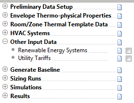
Other Input Data
Figure 40 - Other Input Data - Tasks
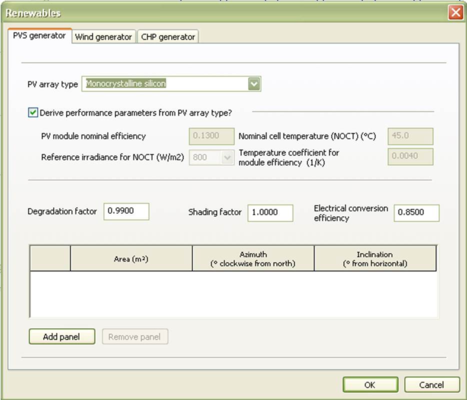
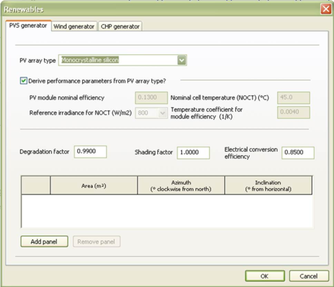
Renewable Energy Systems
There are three types of renewable systems available:
· PVS Generator
· Wind Power
· CHP Generator
· See Apache Sim User Guide for more information on renewables.
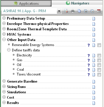
Utility Tariffs
Introduction
Tariff Analysis tool is used to convert the results in energy units from ApacheSim into results in monetary units. The tool allows the user to create real tariffs, which can be saved and shared with other projects, to perform a cost analysis study and easily visualize the improvements from selecting different tariffs.
PRM is based on a comparison of total cost of the proposed and baseline buildings:
PRM documentation: ASHRAE 90.1 Appendix G2.4 Energy Rates: Annual energy cost shall be determined using either actual rates for purchased energy or state average energy prices. Tariff Analysis tool would allow the user to create advance tariffs that replicate the actual rates or to create simple tariffs to input the state average energy price.
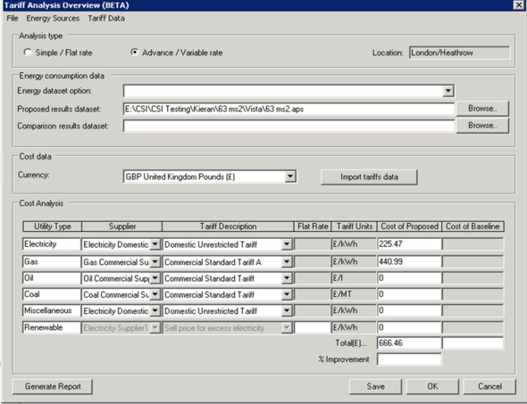
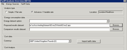
Overview
This is the main window of the tariff Analysis. From this window users can select the tariffs selected, import the aps file from Vista and run the analysis. This window will also display the final cost for each utility for the tariff that has been analysed.
Users are presented with two tariff options;
1. Simple/flat rate
2. Advanced/variable rate
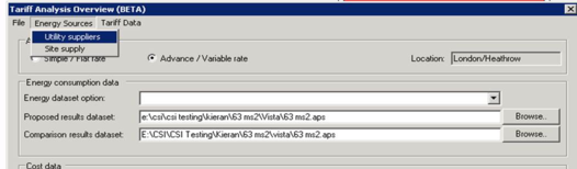
Creating an “Advance/variable rate” Custom Tariff
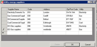
1. In the main tool bar select the “Energy source” tab & select “Utility Supplier”, users can add custom Utility supplier information for all Utilities.
Click the * in the left dialogue allows custom utility energy suppliers to be added to the project.
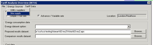
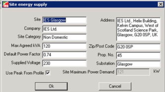
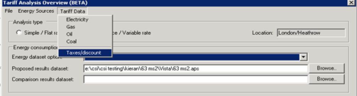
2. The site energy supply information must then complete, this can be found in the “Energy source” tab in the main tariff tool bar.
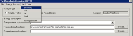
3. Tariff data must now be created for all required utilities, clicking the “Tariff data” tab in the main tool bar will allow users created the required tariffs.
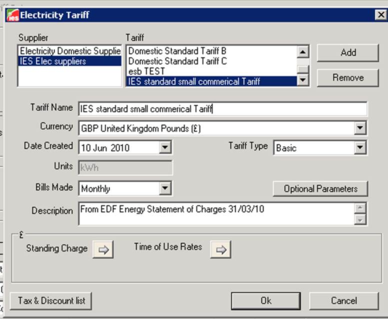
Users will be presented with a listed of suppliers as per step 1. Tariffs can be added & remove to the supplier tariff template. The below dialogue shows the created utility company in the “supplier” window.
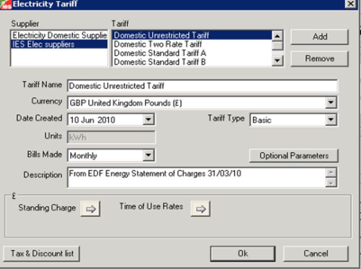
Tariffs can be added to the supplier template by clicking “Add” & naming the tariff. Once the tariff has been added the following information must be set:
· Currency
· Dated created & Tariff type
· Bills Made
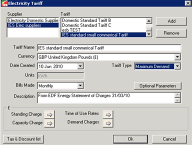
4. Once the above information has been set the detailed “Tariff type” information must be set. Depending on the tariff type selected more icons will become available for example; when the “Basic” tariff type is selected two icons appear “standing rate & time of use rates.
Or with “Maximum Demand” tariff type
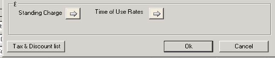
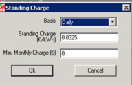
5. Setting charges
Set basic, standing & Min. Monthly charge as indicated above.
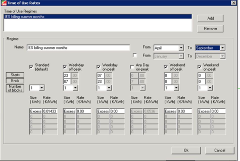
6. Set time of use regimes, detailed variable tariff information can be set here.
MORE DETAIL NEEDED!!
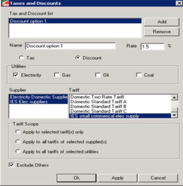
7. Set “Tax/discount” information is required
8. Once the previous steps have been followed the custom tariff data can now be assigned to the utility types.
-
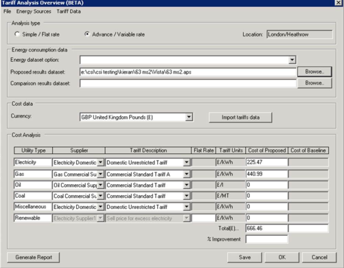
First set the “Energy consumption data” users must select the required vista results aps. Files to be used for the cost analysis.
-
Also set currency type (see above)
-
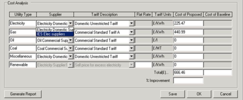
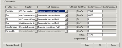
Set “Cost Analysis” information (assign custom tariff templates as previously created)
The resulting Cost output will now reflect the custom created tariff data.
Creating a “Simple/Flat rate” Tariff
For further detail on using the tariff analysis tool please refer to the “Tariff analysis user guide”.
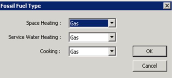
Fossil Fuel Type
All miscellaneous fuel codes are assumed to be electricity except for:
· Space Heating
· Service Water Heating
· Cooking
These end-uses may be either electricity or fossil fuels, and there are two options for fuel code assignment. If the fossil fuel option is chosen, this window allows you to change the fuel type for these fuel codes for the sake of calculating fuel consumption and energy cost.