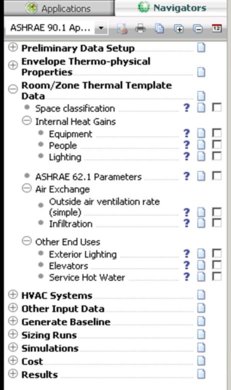
Room/Zone Thermal Template Data
Figure 30 - Room/Zone Thermal Template Data - Sub-categories and Tasks
This navigator stage consists of a number of sub steps that take the user through assigning thermal template information to the Proposed & baseline models.
Space Classification
This step assigns building thermal template information to the proposed model based on the selected thermal template scheme—i.e., the Building area method or Space by space method. This step is closely linked to the “Room/zone Group Assignment” step. Therefore, all spaces in the model must first be assigned to the appropriate groups in either the BLDG or SPACE grouping schemes. This can be done manually or with tools provided in the “Room/zone Group Assignment” step. This step essential performs a global assignment of thermal templates.
Note that you must decide whether to use the Building Area Method OR the Space by Space Method, not a combination of the two. If you opt for the Space by Space method, then ensure that the room group assignment under the building area method is “NOT BLDG”. If you opt for the Building Area method, then ensure that the space by space room group assignment is “NOT SPACE”
The Building Area Method is generally used for early stage analysis where the exact function of every zone in the building has not yet been determined. The Space by Space Method is used more often as it allows the user to assign a particular function to each zone in the building.
Internal Heat Gains
Set Proposed internal gains.
Note: Equipment & People gains should remain the same in both the proposed & baseline models.
Equipment
Baseline & Proposed equipment loads should remain the same except in special cases. Editing the baseline column will apply changes to both models. Editing the proposed column will only edit the proposed model and a message will appear alerting the user that differences in equipment gains between the baseline and proposed must be justified with supporting documentation to the entity reviewing the energy model.
People
Baseline & Proposed equipment loads should remain the same. Editing the value in this dialog will apply the edit to both the proposed and baseline models.
Lighting
Set proposed lighting power densities for space types. The default values provided for the baseline model are in line with the values in ASHRAE 90.1-2007 Chapter 9 Lighting within:
· Table 9.5.1 Lighting Power Densities Using the Building Area Method
· Table 9.6.1 Lighting Power Densities Using the Space-by-Space Method
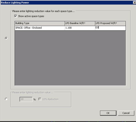
Figure 31 - Reduce Lighting Power - Proposed Manual Value Entry
The dialog above shows the first way that the Lighting Power Density (LPD) can be input for the Proposed Design model through direct entry of a value on the far right column (LPD Proposed W/ft2) for each space type.
Note that the LPD Baseline W/ft2 default value shown for each space or building type aligns with the ASHRAE 90.1-2007 Chapter 9 Lighting tables identified above.
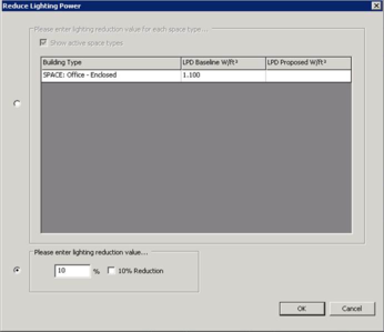
A second approach to establishing the LPD Proposed W/ft2 is shown in the figure below. The user can either directly enter a “% value” (1-100) in the input cell under ‘Please enter lighting reduction value’ or if targeting a 10% reduction can just select the ‘check box’ to the right of the input cell. By providing an input in either one of these ways the LPD Proposed will be derived by taking the LPD Baseline value and multiplying it by (100% - the lighting reduction %). Subsequent entries into the “% reduction” field will reduce the current proposed value by that percentage. If you desire to test alternate reductions compared to the baseline, then reset the proposed LPDs in the top section to match the Baseline, press OK, and then reopen the dialog and enter a new % reduction.
Figure 32 - Reduce Lighting Power Dialog - Custom Inputs
ASHRAE 62.1 Parameters
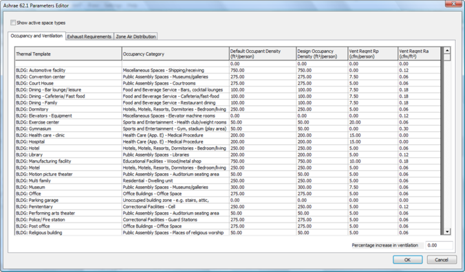
The hyperlink opens the ASHRAE 62.1 Parameters Editor (figure below), which is composed of three tabs and shows all Building and Space options available. In the upper left hand corner the user has the ability to select the check box for ‘show active space types’ to isolate just those utilized within the model. The three tabs include:
-
Occupancy and Ventilation – provides the parameters for each line item that serve as the inputs into the ventilation calculations for the model. The user may select an alternate 62.1 occupancy category for each thermal template if they desire by picking from the drop down menu. The “Default Occupancy” column is not editable – this is the default occupancy level as per the ASHRAE 62.1 standard for each occupancy category. The “Design Occupancy” column can be edited if your proposed building has a different occupancy. Note that any previous edits to occupancy under the “Internal Heat Gains” will be reflected here. Edits here will also be reflected in the Internal Heat Gains/People window. Values for Ra and Rp are derived based on 62.1 Table 6-1.
-
Percentage increase in ventilation – on the lower right side of the dialog box the user can enter a custom value (1-100%) for the percentage increase in ventilation. After inputting a value and hitting ‘ok’ the percentage increase input is applied to all the line items included on this tab. This may be useful if the project is attempting to achieve LEED EQ Credit 2.
-
Exhaust Requirements - provides the parameters for each line item that serve as the inputs into the ventilation calculations for the model. The user may select an alternate exhaust rate category if they desire by picking from the drop down menu. This will update the exhaust flow rates accordingly as per 62.1 Table 6-4. Edits may be applied to the “exhaust per unit” column if this is how they are specified in Standard 62.1 (restrooms, residential kitchens). Customized exhaust flow rates may be specified by selecting “User specified exhaust rate” as the exhaust rate category, and editing one field to specify the rate in terms of cfm/sf, ACH, or exhaust per unit/# of units. A user may also specify whether exhausted zones are served by 100% transfer air or not. If “Y” is selected, that zone will not have any system supply air but will be served by transfer air only.
-
Zone Air Distribution – Provides the parameters for each line item influencing the system design and ventilation calculations. The values can be manually edited within this tab. The “Mandated Supply Air Flow” column should be edited if a zone must receive a specific number of air changes (e.g. hospitals, laboratories, etc.). The Min SA Flow columns should be edited for VAV spaces. Min SA can be specified in terms of % of max, or cfm/sf. If values are input in both columns, the larger of the two will be used. The values for Ez should be input as per 62.1 Table 6-2 and are based on your system design. Note that the baseline model will always use 0.4 cfm/sf for the VAV turndown, and Ez values of 1.0 for cooling and 0.8 for heating as required by 90.1.
Note: If the user has not yet applied the ASHRAE Prototype Data using the ‘Prototype Data (ASHRAE Baseline)’ hyperlink then the ASHRAE 62.1 Parameters Editor will not appear.
Note: If the user has not yet applied zoning to the model using the hyperlink ‘Room/Zone Group Assignment’ then when the ‘show active space types’ check box is selected all the inputs will disappear.
Figure 33 - ASHRAE 62.1 Parameters Editor
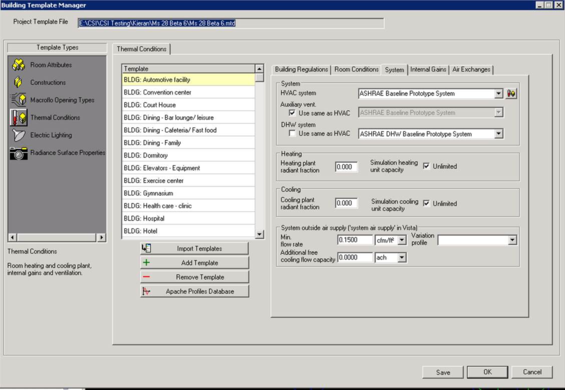
Air Exchange
Building air exchanges include space ventilation rates & air infiltration ACH.
Outside Air Ventilation Rate (simple)
As an alternative to the ASHRAE 62.1 calculations, users can manually input the fresh air rate for each template. Note that these values will not be used unless the 62.1 calculations are disabled in the LoadCalcsVentilation spreadsheet.
Figure 34 - Building Template Manager - System Outside Air Supply inputs
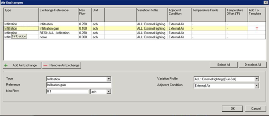
Infiltration
Specify design air infiltration rate ACH. You must select the row in the table with the red ‘T’ in the ‘Add to Template’ column and input the infiltration below in the ‘Max Flow’ box.
Figure 35 - Air Exchanges - Infiltration Inputs
Other End Uses
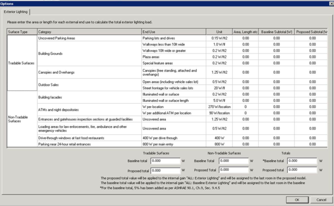
Exterior Lighting
The hyperlink takes the user to the ‘options’ dialog box, which facilitates the calculation of the ‘exterior lighting power allowance’ (baseline) and the proposed model total. The dialog is constructed based on the requirements of ASHRAE 90.1 section 9.4.5 and is divided into two surface types – ‘tradable surfaces’ and ‘non-tradable surfaces’ (similar to Table 9.4.5 within ASHRAE 90.1-2007). The units listed for each end use type are the same as those listed in ASHRAE 90.1-2007.
Baseline Total: To develop the ‘exterior lighting power allowance’ the user needs to input the appropriate values for the project in the ‘Area, Length, etc’ column. The value input here will be multiplied by the unit value for that end use to determine the Baseline Subtotal (W). At the bottom of the dialog box under totals the sum of the Baseline Subtotals is reported in the Baseline Total cell.
Note: the * note express that the baseline total has an additional 5% added as per the requirements within ASHRAE 90.1, Ch.9, Sec 9.4.5.
Note: when entering values in the ‘Area, Length, etc’ column pay close attention to the units for each end use line item. They vary from per location, to per linear foot to per square foot.
Note: when entering values in the cells, double click on the cell to select the overall number in blue, otherwise your entry value will be before the number that is already there. For example if the default value is 0.00 and the user is trying to enter ’10’,if the user only selects the cell once versus twice and inputs ‘10’, then the value that will appear in the cell is ‘100’.
Proposed Total: Once the baseline Subtotals have been determined, the appropriate Proposed Subtotals can be entered in the last column (for each line item). In addition to the ‘Proposed Total’ being calculated under the ‘Totals’ area, the ‘Tradable Surfaces’ and ‘Non-Tradable Surfaces’ totals for both the Baseline and Proposed are calculated as well to provide another reference point to consider.
Please Note the two notes at the bottom of the dialog box describing where the ‘proposed total’ value and the ‘baseline total’ value goes:
-
Proposed Total is applied to the internal gain “ALL:Exterior Lighting” and is assigned to the last room in the proposed model.
-
Baseline Total is applied to the internal gain”ALL:Baseline Exterior Lighting” and is assigned to the last room in the baseline model.
Exterior lighting is controlled using a default formula profile that simulates a photo cell switch. See ASHRAE 90.1 Section 9 for further exterior light details.
The highlighted portions of the figure below show which columns the user would input values within, and the location where the totals are reported.
Figure 36 - Options - Exterior Lighting - Baseline and Proposed Inputs and Calculations
Exterior lighting rules
Entering data…
For each line, if Baseline > 0, then Proposed must also be > 0 (i.e. can’t take credit for unlit surfaces). If Baseline >0 and Proposed = 0, then pop-up a warning message. (applies to both tradable & non-tradable). Likewise, if Proposed >0 and Baseline=0, user will receive a warning message
For each line of tradable surfaces, it is permissible for Baseline > Proposed, or Proposed > Baseline (as long as they are both non-zero values)
For each line of non-tradable surfaces, it is permissible for Proposed>Baseline. However, if Proposed entry < Baseline, then Baseline value is adjusted to be equal to Proposed entry.
Calculating subtotals…
For tradable surfaces, it is permissible for Baseline > Proposed, or Proposed > Baseline (as long as they are both non-zero values)
For non-tradable surfaces, it is permissible for Proposed>Baseline. However, baseline cannot be greater than proposed, (this should not occur if rules above are followed)
Calculating grand total…
Baseline grand total = 1.05 *(baseline tradable + baseline non-tradable)
Note : (5% has been added to the total as per ASHRAE 90.1, Ch.9, Sec. 9.4.5)
Proposed grand total = proposed tradable + proposed non-tradable
If Proposed grand total > Baseline grand total, then proposed exterior lighting design is non-compliant.
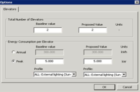
Elevators
Elevator end usage energy can be assigned to the baseline & proposed model in one of two ways, using a peak demand approach or based on an annual kWh rating. The number of lifts must be entered in the dialogue box provided, and should be the same for both baseline and proposed models. The default ASHRAE 90.1 user guide elevator profiles may be used to control this output by selecting the elevator profile for your appropriate building type. In order for the elevator energy to be assigned to the model there must be at least one zone assigned to the elevator grouping scheme.
Figure 37 - Options - Elevators Inputs Dialog Box
Service Hot Water
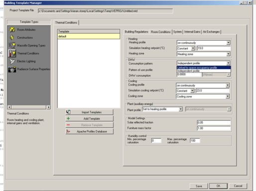
Each thermal template must be assigned a hot water consumption quantity in (l/h max) as per the proposed design. The hot water consumption is directly linked to default ASHRAE 90.1 user guide services hot water profiles, however hot water consumption can also be linked to template “occupancy profiles” by selecting the “link to space occupancy profile” from the “Consumption Pattern” drop down box. DHW plant setup is performed during the baseline HVAC system setup.
The assignment of SHW demand can also be approached by assigning a single SHW demand to a single room with a standalone profile this needs to be done via the query button & pre-baseline generation.
Figure 38 - Building Template Manager Hot Water Consumption input