Generate Baseline & Sizing Runs
Generate Baseline
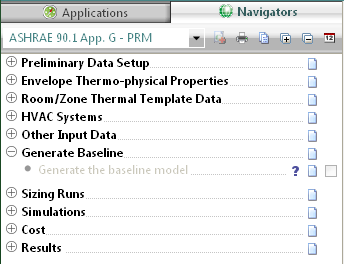
Figure 41 - Generate Baseline Tasks
Generate the Baseline Model
This navigator step automatically generates the baseline models & assigns all relevant baseline information created in previous navigator steps/stages.
Note: This is a very important step in the navigator workflow as it essentially assigns all model data setup in previous navigator steps. If any changes are made to navigator steps after the generation of the baseline models, the baseline models must be re-generated in order to assign updated model data i.e. lighting, ventilation rates, occupancy etc.
Baseline sizing runs will also need to be rerun if changes effect space loads i.e. Lighting, ventilation rates, occupancy etc. If data changes post “baseline generation” do not affect space loads (i.e. exterior lighting) users must still re-do the following navigator steps “Assign room sizing data” & “update fan & coil sizing data”.
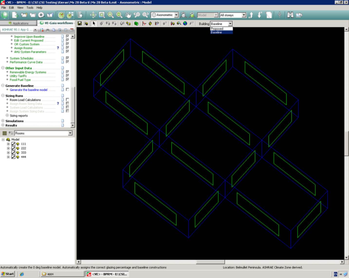
Once the baseline models have been generated users can toggle between the Proposed & Baseline geometry. See above.
Special Baseline Geometry Edits
It might be necessary to make custom geometry edits to the baseline model due to the ASHRAE 90.1 modeling rules. For example if the proposed model has a double skin façade it is required that the baseline model excludes this building feature. The following steps must be followed in order to make custom edits to the baseline model geometry.
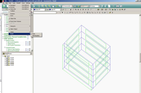
· Enter ModelIt and switch to Baseline model by selecting “view” model in the main tool bar.
· Delete the double-skin façade geometry from the baseline model.
· Return to the BPRM view.
· At this point the newly exposed facade will have default VE constructions assigned. You must manually assign the baseline exterior wall constructions for this facade.
· Once the facade constructions have been assigned, the 0 deg baseline model geometry and construction assignment should now be correct.
· IF after removing the double-skin façade the overall window-to-wall ratio for the entire baseline building exceeds 40%, the newly exposed glazing on facades where the DSF was removed will need to be downsized until the overall 40% requirement is met. (If the proposed building had greater than 40% WWR prior to generating the Baseline building, the glazing area on all exterior facades will have been automatically reduced to meet the requirement.)
· For user that have previously generated the other baseline orientations by running Room Load Calculations after generating the baseline model, these other orientations must be refreshed. This is will be dealt with by running the Room Load calculations in a later step. As these other baseline orientations are based on the 0-degree baseline, there will be no need to repeat the steps above.
Sizing Runs
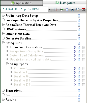
Figure 42 - Sizing Runs Sub-categories and Tasks
Room Load Calculations
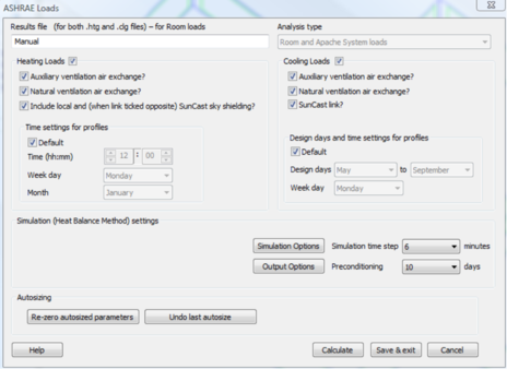
This navigator step automatically opens up the ApacheLoads dialog with default information applied. The user can edit the information relating to the proposed model. The four baseline runs are generated automatically.
As with a normal ApacheLoads run this will generate information relating to room heating and cooling loads. This information is then used to populate the default PRM sizing sheets located in the ‘Loads Data’ folder of the project directory. This will generate flowrate data for use in the proposed and baseline HVAC networks.
Assign Room Sizing Data
This step automatically assigns the sizing data generated from the step above to the proposed and baseline HVAC networks.
System Load Calculations
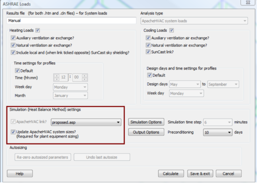
This navigator step opens up the ApacheLoads dialog again, this time an ApacheHVAC network is assigned in order to enable a system sizing calculation. This will provide information to size various system elements i.e. fan and coil data.
As above, the user can edit the information relating to the proposed model. The four baseline runs are generated automatically.
Update Fan And Coil Sizing Data
This step automatically assigns the sizing data generated from the step above to the proposed and baseline HVAC networks.
Sizing Reports
Proposed
This step enables the generation or display of a system level report for the proposed model. The report is broken down into three sections
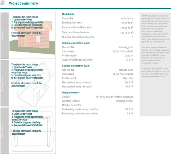
Project Summary:
Contains information relating to the project area and volume, input data for the sizing calculations and design weather data.
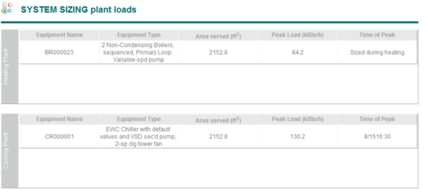
System Sizing Plant Loads:
Contains information relating to the overall performance of the heating and cooling systems e.g. the system type, the floor area served and peak load occurrence.
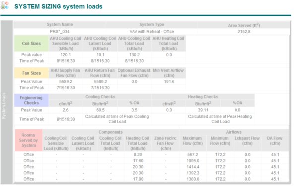
System Sizing System Loads:
Contains detailed information relating to performance of each individual system including sizing data relating to each individual room served by the system.
The report includes data regarding the sizing of the following:
-
Heating and cooling coils
-
-
-
-
Outside air ventilation rates
-
Zone heating coils (reheat)
-
The System Sizing report also includes an Engineering Checks section.
Baseline 0°
The report contains data relating to the Baseline 0o model sizing runs.
Baseline 90°
The report contains data relating to the Baseline 90o model sizing runs.
Baseline 180°
The report contains data relating to the Baseline 180o model sizing runs.
Baseline 270°
The report contains data relating to the Baseline 270o model sizing runs.
Setting Baseline HVAC/DHW manual inputs
Once sizing runs have been performed & auto-sized data has been assigned to the HVAC networks users are required to make some manual edits to the baseline HVAC network in order to comply with ASHRAE 90.1 rules. (These will be autosized/set in future releases).
1. Set baseline “heating source” minimum efficiency. See ASHRAE 90.1 tables 6.8.1A to 6.8.1F. The baseline system efficiency is dependent on the heating plant load; users should use the baseline sizing calculations to determine the required efficiency.
2. Number of baseline boilers if systems 1, 5 or 7 are being modeled. See ASHRAE 90.1 G3.1.3.2. If two boilers are required the boiler Qrat input must be divided by two.
3. Set baseline hot water pump type i.e. Variable speed or constant speed based as per ASHRAE 90.1 section G3.1.3.5.
4. Set chiller plant minimum efficiency as per tables 6.8.1A to 6.8.1F. The baseline system efficiency is dependent on the cooling plant load; users should use the baseline sizing calculations to determine the required efficiency.
5. Set number & type (screw or centrifugal) of baseline chillers for systems 7 & 8 as per ASHRAE 90.1 table G3.1.3.7.
6. Select chilled water reset as per ASHRAE 90.1 G3.1.3.9 ruling.
7. Set chilled water baseline pump type i.e. Variable speed or constant speed based as per ASHRAE 90.1 section G3.1.3.10.
8. Set baseline heat rejection requirements as per ASHRAE 90.1 G3.1.3.11 (system 7 & 8 only).
9. Set baseline condenser heat recovery if required as per ASHRAE 90.1 section 6.5.6.2.1.
10. Users are required to manually set the SHW plant efficiency as per section 7 of ASHRAE 90.1. The boiler tab in ApHVAC contains a prototype SHW system that should be used for the baseline SHW. Users will need to tick the “Use for DHW” & open the heat source & set the required baseline efficiency.
11. Airside economizers need to be engaged for each system air handler, as required by ASHRAE 90.1 G3.1.2.6, via the AHU Parameters dialog prior to system autosizing.
12. Exhaust air energy recovery needs to be engaged and appropriate recovery effectiveness set for each system air handler, as required by ASHRAE 90.1 G3.1.2.10, via the AHU Parameters dialog prior to system autosizing.
13. DX Cooling autosizing is applied to the DX Coil component and this, by default, is set to override the capacity that has been pre-set in the DX Cooling types dialog. This scales the performance curves in the types dialog as needed to match the size of each DX Cooling instance for that type. The DX Cooling types are set up to match ASHRAE 90.1 COP values (fan-power having been removed from EER values provided in ASHRAE Table 6.8.1A, 6.8.1B, and 6.8.1D) for each ASHRAE size range.
· For systems 3, 5, and 6, these are dynamically re-assigned as needed to match appropriate COPs with the sized DX cooling unit.
· For systems 1, 2, and 4, until the same level of automation is provided within the software, users will need to manually check within the Cooling Coil dialog and, if needed, change the selection of pre-defined DX Cooling Type to match the equipment (PTHP vs. PTAC and PSZ-HP vs. PSZ-AC) and COP for the autosized component to those in ASHRAE tables 6.8.1B and 6.8.1D). Again, the COP values for the rated condition in the pre-defined DX Types are based upon the EER values from the ASHREA tables, with fan power having been removed.
14. Air-Source Heat Pumps in System 2 (PTHP) are set up, by default, with ten COP and capacity values forming a performance curve in relation to outdoor temperature (ASHRAE value at rated condition, sans SA fan power, adjusted according to ASHRAE standard performance curves and assumed part-load operation above a 32 °F thermal balance point) to match equipment with capacity in the range of 7-15 kBtu/h (2.05-4.4 kW). For PTHP systems with either lesser or greater capacity, until this is automated in the software, users must replace the COP values in the Heat Pump component dialog with the appropriate set from Appendix B: HVAC Systems Modeling Guidance Specific to ANSI/ASHRAE/IESNA Standard 90.1-2007 in the ApacheHVAC User Guide. There are just three capacity ranges for PTHP heating mode COPs in ASHRAE 90.1-2007.
· Tip: Select just the multiplex layers with Heat Pump components that have an autosized capacity (value on the 10th row at 47 °F) that is either less than or greater than 7-15 kBtu/h (but not both). Then, while in multiplex Global Edit mode, revise the ten COP values simultaneously for all of these.
15. Air-Source Heat Pumps in System 4 (PSZ-HP), similar to system-2 heat pumps, are set up, by default, with 10 COP and capacity values forming a performance curve in relation to outdoor temperature (ASHRAE value at rated condition, sans SA fan power, adjusted according to ASHRAE standard performance curves and assumed part-load operation above a 32 °F thermal balance point) to match equipment with capacity in the range of 65-135 kBtu/h (2.05-4.4 kW). For PSZ-HP systems with either lesser or greater capacity, until this is automated in the software, users must replace the COP values in the Heat Pump component dialog with the appropriate set from Appendix B: HVAC Systems Modeling Guidance Specific to ANSI/ASHRAE/IESNA Standard 90.1-2007 in the ApacheHVAC User Guide. There are just three capacity ranges for PSZ-HP heating mode COPs in ASHRAE 90.1-2007.
· Tip: Select just the multiplex layers with Heat Pump components that have an autosized capacity (value on the 10th row at 47 °F) in a capacity range lesser or greater than 65-135 kBtu/h (but not both) and, while in Global Edit mode, revise the ten COP values simultaneously for all of these. If there are Heat Pumps with autosized capacity in a yet another ASHRAE capacity range, change the multiplex layer selection to include just these layers and repeat the global edit of COP values.
16. For detailed information on baseline HVAC modelling requirements please refer to ASHRAE 90.1 section 6 & Appendix G.
Note : For cases where the Proposed SHW & heating plant are served by the same boiler system the automatic report generator will not match the vista fuel code results, as certain vista energy results are post-proceeded in order to separate the SHW & heating fossil fuel loads.