The hot water boiler model can only be used by a hot water loop. Since heating plants are treated as instances, not types, each (instance of) heating plant is defined in the context of a heat source. Thus no hot water boiler is permitted to serve more than one hot water loop. Hot water boilers can be duplicated using the Copy button within the Heating equipment set in a hot water loop. An “Import” facility (in the heating equipment set tab of a hot water loop dialog) is provided for copying a defined hot water boiler from one hot water loop to another.
The model uses default or user-defined boiler performance characteristics at rated conditions along with the boiler efficiency curve to determine boiler performance at design and off-rated conditions, as specified and simulated, respectively.
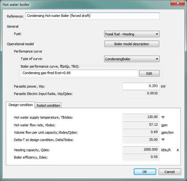
Hot water boiler dialog
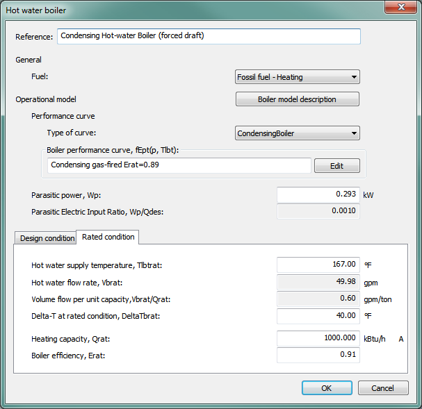
Figure 3 - 23 : Hot water boiler editing dialog
Reference
Enter a description of the component. The reference is limited to 100 characters. It is for your use when selecting, organizing, and referencing any component or controllers within other component and controller dialogs and in the component browser tree. These references can be valuable in organizing and navigating the system and when the system model is later re-used on another project or passed on to another modeler. Reference names should thus be informative with respect to differentiating similar equipment, components, and controllers.
Fuel
Select the fuel, type of energy source, or energy end-use category for the hot water boiler. For scratch-built systems, this will normally be either Natural Gas and for pre-defined systems this is set to Heating (fossil fuel), which is an end-use designations for the ASHRAE 90.1 Performance Rating Method reports (see section 8: Pre-Defined Prototype HVAC Systems and the separate user guide for the PRM Navigator).
Boiler Performance
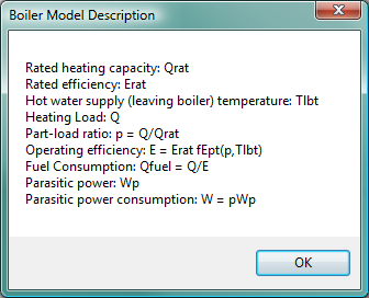
Boiler Model Description
Clicking this button to pop up a summary of the hot water boiler model as shown below:
Figure 3 - 24 : Hot water boiler model description
Rated Condition is Design Condition
When this box is ticked, the rated condition data (see details in the Rated condition sub-tab) is a read-only copy of the current design condition data (see details in the Design condition sub-tab), including any unsaved edits you have made.
Boiler Efficiency Curve, fEpt(p,Tlbt)
The boiler efficiency curve currently selected. Use the Select button to select the appropriate curve from the system database.
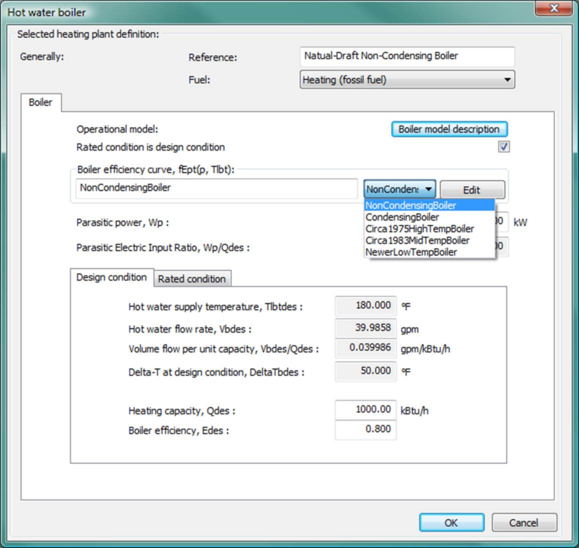
Pre-defined efficiency curves
· Non-condensing boiler (Erat=0.8)
· Condensing boiler (Erat=0.89)
· Circa 1975 high temp boiler
· Circa 1983 mid temp boiler
· Newer low-temp boiler
The first, second, and last of the pre-defined efficiency curves above are the most likely to be applicable for modern hot-water boilers. Keep in mind that these curves describe performance via the “shape” of the curve, whereas the user input for Efficiency at the rated condition shifts the entire curve up or down.
It is essential that the efficiency value entered on the Rated condition tab is the relative to the higher heating value (HHV) and is for the full-load condition at the rated supply water temperature. See more information regarding the user entry for Boiler Efficiency in the Rated Condition section below.
Use the Edit button to edit the curve parameters if needed. The Edit button will pop up a dialog displaying the formula and parameters of the curve, allowing the curve parameters to be edited. You are allowed to edit the curve coefficients, in addition to the applicable ranges of the curve independent variables. When editing the curve parameters, it is important that you understand the meaning of the curve and its usage in the model algorithm.
Also be careful that the edited curve has reasonable applicable ranges for the independent variables. A performance curve is only valid within its applicable ranges. In the case the independent variables are out of the applicable ranges you set, the variable limits (maximum or minimum) you specified in the input will be applied.
Figure 3 - 25 : Drop-down boiler type selection list for the hot water boiler model
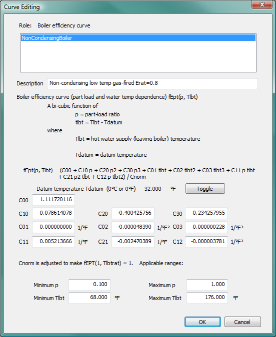
Figure 3 - 26 : Hot water boiler efficiency curves Edit dialog (part load and water temperature dependence)
The boiler efficiency curve (part load and water temp dependence) fEpt(p,Tlbt) is a bi-cubic function of
p = part-load ratio
tlbt = Tlbt – Tdatum
where
T lbt = hot water supply (leaving boiler) temperature
T datum = datum temperature (0°C or 0°F), introduced for the convenience of units conversion of the curve coefficients.
and
f Ept (p,T lbt ) = (C 00 + C 10 p + C 20 p 2 + C 30 p 3 + C 01 t lbt + C 02 t lbt 2 + C 03 t lbt 3
+ C 11 p t lbt + C 21 p 2 t lbt + C 12 p t lbt 2 ) / C norm
where
C 00 , C 10 , C 20 , C 30 , C 01 , C 02 , C 03 , C 11 , C 21 , and C 12 are the curve coefficients
C norm is adjusted (by the program) to make f Ept (1,T lbtrat ) = 1
T lbtrat = rated hot water supply (leaving boiler) temperature.
The boiler efficiency curve is evaluated for each time step during the simulation. The curve value is multiplied by the rated efficiency (E rat ) to get the operating efficiency (E) of the current time step, for the specific part load ratio p and T lbt temperature:
E = E rat f Ept (p,T lbt )
The curve should have a value of 1.0 when the part load ratio equals 1.0 and the T lbt temperature is at rated condition.
A note on the applicable range of part-load ratio p:
The minimum p is used by the program as the minimum part-load ratio for continuous operation, under which the boiler starts cycling on and off.
The maximum p should usually be 1.0. During the simulation, a part-load ratio greater than 1.0 is a sign of boiler undersizing.
Also note that the bi-cubic form of the boiler efficiency curve can be used in simplified forms. For example, to use it in a bi-quadratic form, simply specify C30, C03, C21, and C12 to be zero. To use it in a quadratic-linear form, simply specify C30, C03, C02, and C12 to be zero.
Parasitic Power, Wp
Enter the boiler parasitic power (kW) at the full boiler load.
The parasitic power represents the parasitic electric power consumed by forced draft fans, fuel pumps, stokers, or other electrical devices associated with the boiler. For a natural draft gas fired boiler, W p may be zero or close to zero. This parasitic power is included whenever the boiler is operating, and the model assumes that this parasitic power does not contribute to heating the water.
The parasitic power is adjusted with boiler capacity when the boiler is autosized and follows the load in operation (in both cases maintaining the Parasitic Electric Input Ratio).
Parasitic Electric Input Ratio, Wp/Qdes
The ratio between the boiler design parasitic power consumption and the boiler design heating capacity. It is automatically derived by the program using the provided boiler parasitic power and the boiler design heating capacity, and does not need to be specified. Once the Parasitic Power has been set for the Rated full-load condition, the Parasitic Electric Input Ratio calculated at that time is maintained. Thus the user input for Parasitic Power will be adjusted when boiler capacity is modified by autosizing. The Parasitic Electric Input Ratio is also maintained in operation, such that the simulated parasitic power at any particular time step will follow the variation in boiler load.
Design Condition
Hot Water Supply Temperature, Tlbtdes
The design hot water supply temperature (leaving boiler water temperature) is specified in the associated hot water loop dialog (in the hot water loop tab) and is displayed here as a derived parameter.
Hot Water Flow Rate, Vbdes, Vbdes/Qdes, ∆Tbdes
V bdes , V bdes /Q des , and ∆T bdes are three different options for specifying design hot water flow rate. Currently it is specified in terms of ∆T bdes (the difference between the design hot water supply and return temperatures). It is specified in the associated hot water loop dialog (in the hot water loop tab) and is displayed here as a derived parameter. The other two options (V bdes and V bdes /Q des (the ratio between design hot water flow rate (V bdes ) and design heating capacity (Q des ).) are automatically derived by the program based on the specified ∆T bdes and cannot be edited.
Note: If there is an air-source heat pump or CH(C)P plant attached to the boiler loop, you should calculate what proportion of the total load the boiler takes at the peak condition (which is hard for the software to determine automatically) and reduce ∆T bdes by this factor. (In general, ∆T bdes is the temperature rise across the boiler, not the water loop.)
Heating Capacity, Qdes
When ‘Rated condition is design condition’ is ticked, enter the design heating capacity.
When ‘Rated condition is design condition’ is not ticked, the design heating capacity is always a copy of heating capacity at rated condition and does not need to be edited.
This parameter is autosizable. When this parameter is autosized, its value in the field and its autosizing label ‘A’ become green.
Boiler efficiency, Edes
The boiler efficiency at the Design condition is derived using design and rated condition data (such as Design supply water temperature and Rated boiler efficiency) provided elsewhere and is not editable. For more information, see Boiler efficiency under Rated condition, below.
Rated Condition
Rated condition and Design condition are provided for flexibility in specifying hot water boiler data.
The rated condition is the basis for the calculation of boiler characteristics at simulation time. The rated condition is usually the condition at which the boiler characteristics are specified by a manufacturer. However, it can optionally be the design condition, in which case the user selects Rated = Design.
The design condition is the condition applying at the time of design peak boiler load.
Figure 3 - 27 : Hot water boiler efficiency curves Edit dialog (part load and water temperature dependence)
To use catalogue boiler data, enter capacity and efficiency at the rated condition and read the derived capacity and efficiency at the design condition. The model sets the design capacity as equal to the rated capacity. Design efficiency, however, may differ from rated efficiency if the user specifies a design hot water supply temperature that is different from the rated hot water supply temperature.
To size a boiler based on a design load, enter a capacity and efficiency at the rated condition; then adjust the efficiency to produce the desired derived efficiency at the design condition (allowing for a margin of over-sizing). Again, the Design capacity will always equal the rated capacity.
If the rated condition and design condition are one and the same, tick the Rated condition is design condition checkbox, which makes the rated condition data a linked copy of the design condition data.
Hot Water Supply Temperature, Tlbtrat
When ‘Rated condition is design condition’ is ticked, the rated hot water supply temperature (leaving boiler water temperature) is a dynamic copy of the design hot water supply temperature.
When ‘Rated condition is design condition’ is not ticked, enter the rated hot water supply temperature.
Hot Water Flow Rate, Vbrat, Vbrat/Qrat, ∆Tbrat
V brat , V brat /Q rat , and ∆T brat are three different options for specifying rated hot water flow rate. Currently it is specified in terms of ∆T brat (the difference between the rated hot water supply and return temperatures). The other two options (V brat and the ratio between rated hot water flow rate (V brat ) and rated heating capacity (Q rat )) are automatically derived by the program based on the specified ∆T brat and cannot be edited.
When ‘Rated condition is design condition’ is ticked, the rated hot water flow rate is a dynamic copy of the design hot water flow rate. When ‘Rated condition is design condition’ is not ticked, enter the rated hot water flow rate.
Heating Capacity, Qrat
When ‘Rated condition is design condition’ is not ticked, enter the rated heating capacity.
When ‘Rated condition is design condition’ is ticked, the rated heating capacity is always a copy of heating capacity at design condition and does not need to be edited.
Boiler efficiency, Erat
Enter the boiler thermal efficiency (for the burner and heat exchanger assembly) at the rated full-load condition, expressed as a value between 1.00 and 0.00. This does not include blowers on forced-draft boilers or similar parasitic loads, which must be separately entered in the boiler dialog.
It is essential that the Boiler efficiency entered on the Rated condition tab is the value at full load and at the Rated hot water supply (boiler leaving) temperature entered on the Rated condition tab.
Boiler efficiency entered here should always be the relative to the higher heating value (HHV) of the fuel, rather than lower heating value (LHV). When the available boiler efficiency data is based on the lower heating value (LHV) of the fuel, multiply the thermal efficiency by the lower-to-higher heating value ratio for the fuel. Typically, for natural gas, this ratio will be on the order of 0.91.
As the evolution of condensing boiler technology and low-temperature applications have led to flatter performance curves with rated full-load efficiency nearer to that of the peak part-load efficiency, the pre-defined “Condensing boiler” performance curve may be overly steep with respect to representing the part-load efficiency of certain notably high performance condensing boiler applications. A boiler model with performance based upon return rather than supply water temperature might handle this more gracefully. However, more often than not, erroneous part-load efficiencies result from users incorrectly entering the boiler efficiency associate with a part-load condition or a lower SWT than has been entered in the Rated condition tab.
The source for the “Condensing boiler” performance curve is the “Gas-fired condensing boiler curve” provided by the US DOE with EnergyPlus and represents normalized boiler efficiency coefficients derived from two boilers; one with 40°C supply and 30°C return, and one with 75°C supply and 60°C return. The value for rated efficiency associated with the original curve data is 0.89. Depending on the setting for SWT, entering a full-load value for Erat significantly higher than 0.89 when using the “Condensing boiler” curve can result in part-load efficiency values in excess of 100%.
For example, with Rated SWT set to 140°F (60°C) and Rated full-load efficiency set to 0.91, the curve will yield a rated efficiency of 0.99 at 20% load. This is reasonable if the real-world application uses the same SWT and large delta-T to achieve a low return temperature, minimizing condensation at the burner HX while maximizing condensation at the secondary HX. With these rated inputs and design HWL temperature of 120°F (49°C), design full-load efficiency will be 0.927 and design efficiency at 20% load will remain 0.99. Thus the above are perhaps the upper bounds of realistic values for condensing boiler efficiency. On the other hand, if one were to leave the Rated SWT set to 140°F (60°C) and raise value entered for the Rated full-load efficiency to 0.94—a value that would be reasonable at either much less than 100% load or a very low return water temperature—the curve will return an efficiency value of 1.02 at 20% load. If the user were then to set the SWT for the connected Hot Water Loop—i.e., the Design SWT for the boiler—to 120°F (49°C) with the assumption that this will be correctly associated with the efficiency value of 0.94 that they entered, the over-prediction of part-load efficiency will remain: The calculated design full-load efficiency at the lower design SWT of 120°F will be 0.957 and design efficiency at 20% load will remain over-predicted at 1.02.
Air-source heat pump
The air-source heat pump (ASHP) can be the primary heat source for any heating coil or radiator. Starting from VE6.4.0.5, there are three kinds of air-source heat pumps modeled in ApacheHVAC:
· Air-to-water heat pump (AWHP) in the context of a hot water loop
· Air-source heat pump (ASHP) with generic heat output in the context of a generic heat source
· Air-to-air heat pump (AAHP) which is always in a one-to-one relationship with a heating coil
The air source for the air-source heat pumps is always assumed to be outside air.
Heat pump update
As the interfacing of heat pumps in ApacheHVAC has been overhauled for VE 6.4.0.5, Air source heat pumps (ASHPs) present in systems from prior versions are automatically updated. The rules for the updating procedure can be summarized as follows.
· Heat pumps are no longer displayed in the air network. They are replaced in the network by a straight connector.
· The air source for air-source heat pumps is now always assumed to be outside air.
· A pre-6.4.0.5 ASHP with Hot water boiler as backup heat source is upgraded to an Air-to-water heat pump attached to a Hot water loop served by the same Hot water boiler.
· A pre-6.4.0.5 ASHP with Part load curve heating plant as backup heat source is upgraded to one of the following:
1. Air-to-air heat pump type (AAHP) serving the heating coil that was associated with the old heat pump; the converted AAHP is assigned a Generic heat source as backup (upgraded from the old Part load curve heating plant); or under the circumstances described below…
2. Air-source heat pump directly associated with a Generic heat source (this is within the Generic heat source dialog, which in this case represents an upgrade from the old Part load curve heating plant), if one or more of the following are true:
a) The old part load Heat source serves a room radiator or similar room unit.
b) The old part load Heat source serves more than one heating coil and these do not belong to the same multiplex.
c) The old part load Heat source serves DHW.
d) The old part load Heat source serves an Absorption chiller.
· When converting old ASHPs to the new AWHPs, parameters are copied over from the old ASHPs to the new AWHPs as would be expected.
· When converting old ASHPs to the new AAHP type(s), data fields in the first two columns (COP source temperature and COP) of the ASHP performance table are copied over from the old ASHPs to the new AAHP type(s). The third column of data is converted from ‘Output (kW)’ in the old ASHP to ‘Output (%)’ in the new AAHP type. The conversion method is to transfer the last column of data to percentage values expressed as a percentage of the heat pump’s capacity, with the last row Output (kW or kBtu/h) value assumed equal to 100%.
· The maximum load percentage for the AAHP type—the bottom row value for Output (%)—is fixed at 100%. Values in other rows for the Output (%) column must be between 0% and 100%. The assumption underlying this is that capacity increases with source temperature.
· When converting old ASHPs to the new AAHP type(s), a ‘sharing rule’ is applied: when possible, the minimum number of AAHP types and GHS instances are created for each multiplexed ASHP.
The sharing rule implies that there are two cases where the multiplexed ASHP with backup part-load heat source can be considered as having the same ‘shape’ and therefore will be converted to a single AAHP type:
1. All the data fields contain identical values within the multiplexed ASHPs associated with a common part-load backup heat source. Obviously, these ASHPs will translate to the same AAHP type. This case happens when multiple ASHPs are replicated in the process of multiplexing a system with an ASHP on the initial layer, without any user edits in the individual ASHPs on subsequently created layers.
2. The first two columns of data (Source temp. and COP) in the ASHP’s performance table are the same, and although the third column has different values, all data in this column are in the same proportions—i.e., if you transfer the last column data to percentage values expressed as a percentage of the capacity (setting the last row value to 100%), then you will get the same column of percentages. This is normally the result of autosizing an old system with multiplexed otherwise identical ASHPs serving multiplexed heating coils. The ASHP on each multiplex layer is likely to have a unique capacity after autosizing, with part-load values in other rows proportionally scaled, based on their previous values expressed as a fraction of the maximum.
In all other cases, multiplexed ASHPs coupled to part-load backup heat sources are considered as having different ‘shapes’ and are thus converted to separate AAHP types.
· When updating an old ASHP to an Air-to-air heat pump (AAHP) in cases where this heat pump is associated with a single heating coil, the capacity from the old ASHP (the figure shown for ‘Output’ in the last row of its performance table) is assigned to the associated heating coil in the updated system.
This rule means that the capacity assigned to a coil may be changed by the updating process, so that if (at certain time steps) a heating coil reaches its capacity, it will behave differently in the updated system. However, this is better than changing the performance characteristics of the heat pump (which would be the result if the coil capacity remained unchanged), in which case the energy consumption at every time step would have to change.
Air-to-water heat pump (AWHP) and generic Air-source heat pump (ASHP)
The air-to-water heat pump (AWHP, in the context of a hot water loop and accessed from the Pre-heating tab of the ‘Hot water loop’ dialog) or Air-source heat pump (ASHP, in the context of a generic heat source and accessed from the ‘Generic heat source’ dialog) is essentially the old air source heat pump but interfaced in a different way. Instead of being drawn on the system air network, it is specified in the heat source dialogs (as shown above in the ‘Generic heat source’ dialog and in the ‘Pre-heating’ tab of the ‘Hot water loop’ dialog). In the background of ApacheHVAC, air-to-water heat pumps are treated as actual components (instances) rather than ‘types’, in contrast to the Air-to-air heat pumps, which are treated as ‘types’, not ‘instances’.
The new AWHP will always use outside air, rather than a user-selected location on the airside network, as its heat source (which is nearly always the case in reality).
Note the change on where the link between an AWHP and a backup heat source is specified. Pre-v6.4.0.5, this was specified in the old ASHP dialog through the ‘Backup heat source’ parameter. From v6.4.0.5 onward, it is determined in the heat source dialogs, given that the AWHP can be added only as a pre-heating device on a ‘Hot water loop’ or similar option in the ‘Generic heat source’ dialog.
Although determined in a different location and having a more appropriate “parent-child” relationship from the user perspective, the one-to-one relationship (constraint) between an AWHP and a backup heat source still exists (for now): only one AWHP may be specified as the pre-heating device for a given generic heat source or hot water loop.
In the case of an AWHP linked to an HWL the simulation will incur pumping power when the AWHP is running and the main (‘backup’) heat source is not.
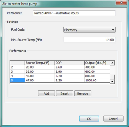
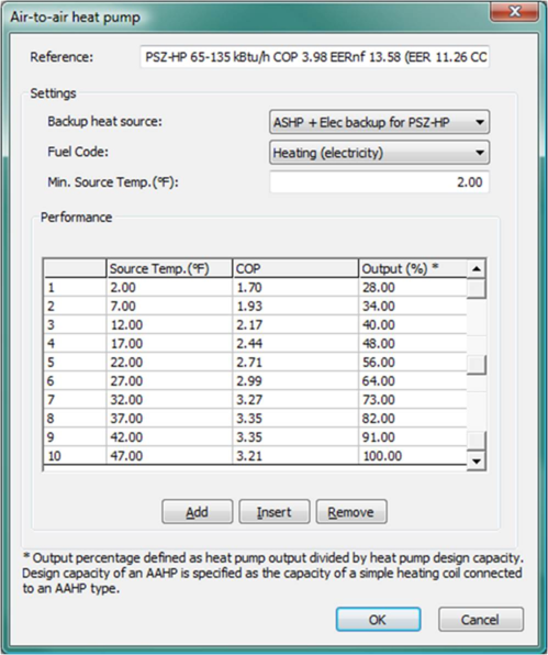
Figure 3 - 28 : AWHP accessed from the Pre-heating tab of the ‘Hot water loop’ dialog.
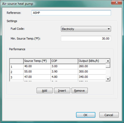
Figure 3 - 29 : ASHP accessed from the ‘Generic heat source’ dialog with illustrative values, including modest capacity and a relatively high minimum source temperature as might be used to model domestic hot water (DHW) heating via heat pump in a warm climate with an otherwise all-electric, cooling-centric space-conditioning system.
Air-to-water and air-source heat pump settings
Reference
Enter a description of the component. The reference is limited to 100 characters. It is for your use when selecting, organizing, and referencing any component or controllers within other component and controller dialogs and in the component browser tree. These references can be valuable in organizing and navigating the system and when the system model is later re-used on another project or passed on to another modeler. Reference names should thus be informative with respect to differentiating similar equipment, components, and controllers.
Fuel Code
Select the fuel, type of energy source, or energy end-use category for the air-to-water or air-source heat pump. For scratch-built systems, this will normally be Electricity and for pre-defined systems this is set to the Heating (electricity) end-use designation for the ASHRAE 90.1 Performance Rating Method reports.
Minimum Source Temperature
The heat pump is assumed to switch off completely when the source temperature drops below this value. Above this value, the heat pump is assumed to meet as much of the load as it can, with the heat source being brought in to top up this demand if required.
Air-to-water and air-source heat pump performance
Source Temperature
This line of information describes the variation in the performance of the heat pump as the source temperature varies. Enter the source temperature. Up to ten points may be used to define the variation of performance with source temperature. Enter the points in ascending order of source temperature.
Heat Pump COP
Enter the coefficient of performance of the heat pump at the corresponding source temperature. This value is the useful heat output divided by the total fuel energy consumption associated with the operation of this device (excluding electrical consumption of any distribution pumps included in heating plant components).
Output
Enter the maximum heat pump output at the corresponding source temperature. If the demand for heat output exceeds this value then the heat source is used to make up the extra demand.
Air-to-air heat pump (AAHP)
The air-to-air heat pump (AAHP) is a new component type to be used in place of an ASHP to represent an air-to-air heat pump serving a simple heating coil.
Data describing AAHPs is organized in an air-to-air heat pump list. Entities on this list are AAHP ‘types’, not instances (in contrast to AWHPs).
A simple heating coil (SHC) can specify an AAHP of a named type as its heat source, as the ‘Air-to-air heat pump’ system type.
The AAHP type data consist of a part-load curve formulated in terms of fractional load (load divided by design load). In other respects its data is similar to that for an old ASHP.
Thus the ‘shape’ of the heat source (fractional part load curve) is an attribute of the AAHP type, and its size (essentially the size of the simple coil) is stored as an attribute of the heating coil. Only the size parameter will need to be updated during system sizing.
Hence, the AAHP instance sizing would be automatically covered by the normal sizing process for its connected simple heating coil. No additional sizing process is needed for the AAHP types.
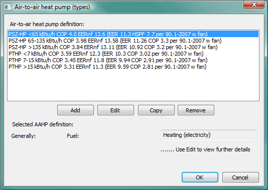
The AAHP component is accessed through the toolbar button shown below. Clicking this button opens up the Air-to-air heat pump (types) dialog.

Toolbar button for Air-to-air heat pump (types) list
Figure 3 - 30 : Air-to-air heat pump (types) dialog
This facility supports defining the performance characteristics of one or more AAHP types.
The entities defined here are types. A single AAHP type may be assigned to many heating coils. At the time of simulation instance of the AAHP type is automatically created for each heating coil to which the AAHP type is assigned. In this respect AAHP differ from the AWHP attached to a hot water loop (or the ASHP attached to a generic heat source).
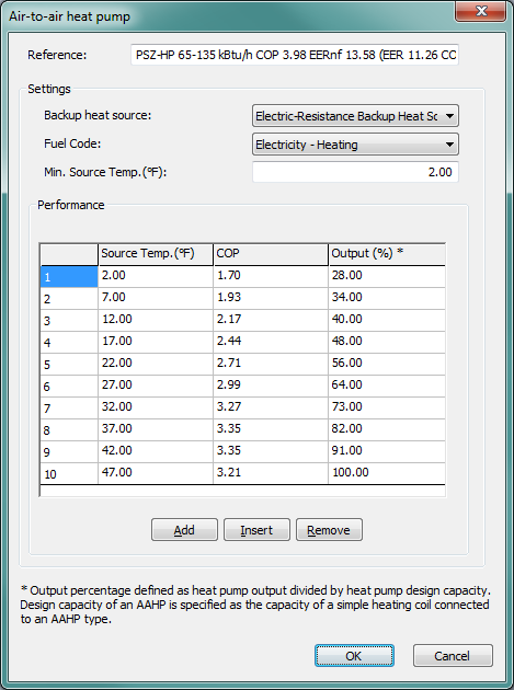
Figure 3 - 31 : Air-to-air heat pump dialog with default inputs as provided for the AAHP in the pre-defined packaged single-zone heat pump (04 PSZ-HP) system when the autosized load range is >135 kBtu/h.
Air-to-air heat pump settings
Reference
Enter a description of the component. The reference is limited to 100 characters. It is for your use when selecting, organizing, and referencing any component or controllers within other component and controller dialogs and in the component browser tree. These references can be valuable in organizing and navigating the system and when the system model is later re-used on another project or passed on to another modeler. Reference names should thus be informative with respect to differentiating similar equipment, components, and controllers.
Backup heat source
Select the backup heat source for the AAHP type. Note that only heat sources of the generic type will be available to be selected as the backup heat source for an AAHP type.
Fuel Code
Select the fuel, type of energy source, or energy end-use category for the air-to-air heat pump. For scratch-built systems, this will normally be Electricity and for pre-defined systems this is set to the Heating (electricity) end-use designation for the ASHRAE 90.1 Performance Rating Method reports.
Minimum Source Temperature
The heat pump is assumed to switch off completely when the source temperature drops below this value. Above this value, the heat pump is assumed to meet as much of the load as it can, with the backup heat source being brought in to meet remaining demand as required.
Typically, the minimum source temperature is the temperature at which the unit will be shut off to optimize overall system operating efficiency or similar. For example, this may be the outdoor temperature at which the heat pump COP would drop to 1.0 when the backup is electric resistance heat. Once the heat pump COP drops to 1.0 or near that value, it may no longer make sense to operate it when the much simpler and therefore less costly to operate electric resistance heating is equally efficient.
Air-to-air heat pump performance
Source Temperature
This line of information describes the variation in the performance of the heat pump as the source temperature varies. Enter the source temperature. Up to ten points may be used to define the variation of performance with source temperature. Enter the points in ascending order of source temperature.
Heat Pump COP
Enter the coefficient of performance of the heat pump at the corresponding source temperature. This value is the useful heat output divided by the total fuel energy consumption associated with the operation of this device (excluding electrical consumption of any distribution pumps included in heating plant components).
Output
Enter the maximum heat pump output at the corresponding source temperature. If the demand for heat output exceeds this value then the backup heat source (if present) is used to make up the extra demand.
Note that AAHP Output is in the form of a percentage value. Output percentage is defined as the heat pump output ( kW in SI units; kBtu/h in IP units ) divided by the heat pump design capacity. Design capacity of an AAHP is specified as the capacity of a simple heating coil connected to an AAHP type.
Modeling heat pump temperature and part-load dependent performance
Figure 3 - 32 : Air-source heat pump dialog with illustrative inputs
The air-source heat pump models (ASHP, AWHP, and AAHP) in ApacheHVAC provide straightforward and very clear means of modeling of the following relationships:
· Air-source-temperature dependent COP
· Air-source-temperature dependent output (heating capacity, not to be confused with load)
· Minimum source temperature for operation
This model does not, however, provide a direct means of accounting for the additional dimension of part-load-dependent COP. The following method of doing so has been used in the pre-defined AAHPs as an illustration of one possible approach to this and can be reproduced by users as appropriate.
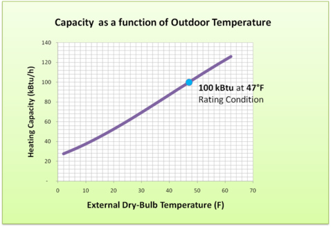
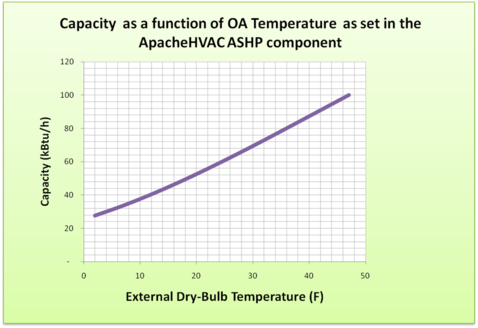
Figure 3 - 33 : Air-source heat pump performance associated with illustrative inputs in Figure 3-32
Figure 3 - 34 : Graphic representation of the illustrative inputs in Figure 3-32
Modeling heat pump temperature and part-load dependent performance
Figure 3-32 ,
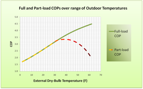
Figure 3-33 , and

Figure 3-34 above show illustrative inputs for the ASHP dialog and the relationship between these and the heat pump capacity curve and full-load COP curve.
To account for both change in performance (output and COP) with outdoor temperature and reduced COP at part load, it is useful to create simple graphs of the first two of these (green and purple lines in Figure 3-33 ) and then use simulation results to determine part-load values corresponding to outdoor temperature above the outdoor temperature at which the heat pump output is well matched to heating load. At lower outdoor temperatures, the heat pump will be fully loaded, and thus the model should use the full-load COP (dashed yellow line segments in Figure 3-33 ). At higher outdoor temperatures, which normally are associated with reduced heating loads, the heat pump COP will tend to decrease with load (dashed orange and red line segments in Figure 3-33 ). If the heat pump is never to be fully loaded at the outdoor temperature associated with the rating condition (e.g., at 47 °F), which is a function of design sizing condition and oversizing, it may be that the COP provided at the rating condition will never be applicable. In other words, because the COP will tend to decrease both with decreasing load (as the outdoor temperature rises above that which corresponds to the fully loaded condition) and with decreasing outdoor temperature below the rating condition, the heat pump COP will always be less than the COP when fully-loaded at the rating condition.
Simulation results were used to determine that the load placed upon the ASHP after sizing would be 100% at 32 °F, with supplemental heat from the backup heat source increasingly required below that temperature and, above 32 °F, heating load gradually diminishing to 40% at an outdoor temperature of 62 °F. This information was used to determine the part-load COP curve (dashed line) in Figure 3-33 . To facilitate insertion of the autosized capacity (based upon the winter heating design day conditions for the project location) in the row associated with the ARI testing condition (47 °F) used to determine the equipment capacity and COP, the curves are intentionally truncated to end at 47 °F.
In the example in Modeling heat pump temperature and part-load dependent performance
Figure 3-32 ,

Figure 3-33 , and
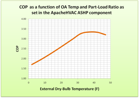
Figure 3-34 above, the COP for the fully loaded heat pump at the 47 °F rating condition would be 4.0, and this is the outdoor temperature at which the full rated capacity would be available. However, when sized to meet the full load at 32 °F, the heat pump load is 81% of full load at 47 °F outdoor temperature for this example. Thus the maximum COP of 3.35 occurs at an outdoor temperature of approximately 37 °F and 95% load and the COP is just 3.2 at 47 °F and 81% load.
The inputs in the ASHP dialog could be extended to warmer temperatures if needed. Because the dialog accepts just 10 rows of data, the spacing between data points would need to be revised to accommodate this. Because the model uses linear interpolation between the data points provided, and the COP and capacity curves are both relatively flat between about 17 and 32 °F for this particular data set, this would be the best region of the curve to be represented by a reduced density of data points.
Heat Transfer Loop
The heat transfer loop component is developed firstly to facilitate the simulation of water-to-air heat pump (WAHP) systems in VE 2012 (v6.5). In this first phase, the heat transfer loop must serve water-to-air heat pumps. It will eventually be extended to support heating, cooling, and collecting or rejecting heat via hot/cold-water coils on the airside network and to serve the purpose of transferring heat between other water loops (heat transfer loops, chilled water loops, hot water loops, etc.).
Water-to-air heat pump systems
A water-to-air heat pump system consists of multiple zone-level water-to-air heat pumps connected to a common water loop. The common water loop is used by each individual heat pump as a source for acquiring heat or sink for rejecting heat. Some of the WAHP units on the loop may be in cooling mode, while others may be in heating mode. For all WAHP units on given Heat transfer loop, this common loop simultaneously acts a resource for any WAHP in heating mode and a sink for any AWHP in cooling mode.
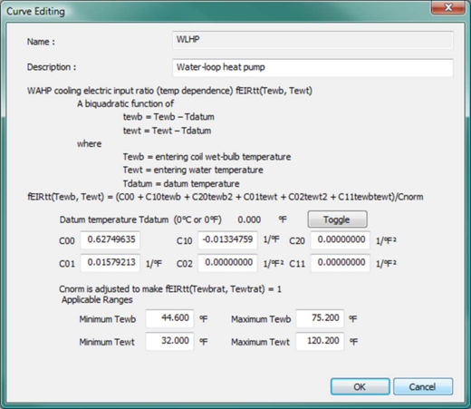
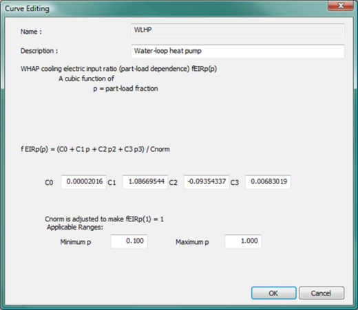
A conventional WAHP system uses a boiler to add heat to the common loop and a cooling tower or fluid cooler to reject excess heat from the common water loop. This is also is referred to as a “water-loop heat pump” (WLHP) system, and the WAHP model includes a set of WLHP performance curves for this type of application. Typically, the boiler operates to maintain the minimum loop supply water temperature around 68°F (20°C), while the cooling tower or fluid cooler operates to maintain the maximum loop supply water temperature of something like 86°F (30°C). Between the maximum and minimum, the loop supply water temperature is allowed to float.
A ground-water WAHP system uses an open water loop that draws water from a lake, well, or similar resource. The WAHP model includes a pre-defined set of GWHP performance curves for this type of application. The loop water temperature is assumed to float with both the loads and the lake/well water temperature, with the latter represented as an annual temperature profile on the source side of a water-to-water heat exchanger. Typical rating conditions in terms of water loop temperatures for this type of system are 50°F (10°C) for heating and 59°F (15°C) for cooling.
A ground-source heat pump system uses a closed loop of polymer tubing acting as a “geo-thermal heat exchanger”. The loop water temperature floats with the ground temperature, loop load, and the characteristics of the geo-thermal heat exchanger. Typical rating conditions in terms of common water loop temperatures for this type of system are 32°F (0°C) for heating and 77°F (25°C) for cooling. User should be cautioned, however, that this model does not include detailed geo-thermal heat exchanger characteristics or the capacitance or thermal mass of the earth around the tubes, and therefore has no means of determining the extent to which this earth may become thermally depleted or saturated over time. So, while this model can be used to represent a ground-source heat pump system, it is limited to representing that which can be suitably described by a seasonal ground-source temperature profile. For more detailed modeling of ground-source heat pump systems, including characteristics of bore fields and geo-thermal heat exchangers, see Appendix D: Ground-Source Heat Pump Modeling using ApacheHVAC loads and Gaia Geothermal Ground-Loop Design.
Two components are provided for modeling WAHP systems:
· Water-to-air heat pump
· Heat transfer loop
The WAHP units must be connected to (served by) a common Heat Transfer Loop (HTL) by selecting the appropriate HTL within the heating/cooling coil dialogs. Details of the Water-to-air heat pump component and modeling are covered in section 2.9. This section provides details for the Heat transfer loop component.
Heat sources (or sinks) available on the heat transfer loop may include the following:
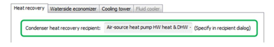
· For heating: solar water heater (SWH), water source heat exchanger (WSHX), condenser heat recovery (CHR), air-to-water heat pump (AWHP), combined heat and power (CHP), sequenced heating equipment set
· For cooling: water source heat exchanger (WSHX), cooling tower (CT) or fluid cooler (FC)
Note that the ground-water heat pump implementation in this phase is intended for modeling ambient- and ground-water sources (oceans, rivers, lakes, ground water, wells, etc.) with a constant or readily profiled water temperature. If you choose to use this component to model a ground loop above the water table (i.e., a “geo-thermal heat exchanger”), please be aware that this will not include a dynamic model of the ground mass as a source and sink to be thermally depleted and recharged over time. For more detailed modeling of ground-source heat pump systems, including characteristics of bore fields and geo-thermal heat exchangers, see Appendix D: Ground-Source Heat Pump Modeling using ApacheHVAC loads and Gaia Geothermal Ground-Loop Design.
Heat transfer loop configurations
Two options are offered for the Heat transfer loop configuration:
· Primary-only : Loop flow is maintained by a primary pump that can be either a variable-speed pump (i.e., using a variable-speed drive) or constant-speed pump riding the pump curve.
· Primary-Secondary : Loop flow is maintained by a combination of primary and secondary pumps. The primary pump is assumed to have constant flow when it is on. The secondary pump can be either a variable-speed pump with VSD or a constant-speed pump riding the pump curve.
Selecting the Primary only configuration effectively removes the constant-speed primary loop pump from the diagram in Figure 3-35 .
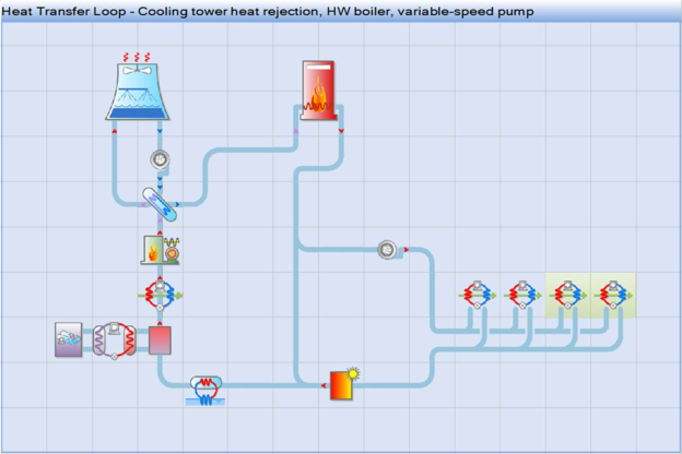
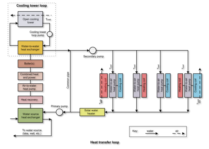
Figure 3 - 35 : Heat transfer loop with primary-secondary configuration, a range of optional heat acquisition and heat rejection devices, and zone-level water-loop (water-to-air) heat pumps . The fluid cooler alternative to the cooling tower and available heat recovery connections are not shown.
Figure 3-35 shows the conceptual heat transfer loop configuration. In this configuration, the heat transfer loop uses a primary-secondary loop configuration. On the secondary loop, source water is supplied to multiple water-to-air heat pump units connected in parallel. Water-to-air heat pump units are used to serve both simple heating coils and simple cooling coils. A optional solar water heater can be included on the return side of the secondary loop, downstream of the heat pumps (i.e., as a pre-heating source on the secondary return pipe).
On the primary loop, there are five optional heat sources connected in a pre-defined series configuration. These heat sources could include: WSHX (water source heat exchanger), HR (Heat recovery), AWHP (Air-to-water heat pump), CHP (Combined heat and power), and sequenced boiler(s) or similar equipment in a Heating equipment set. Each of these, when included, adds heat to raise the loop water temperature to the supply water temperature set point. If the first device in line to do so does not achieve the set point, the next device in series after it will have the opportunity to address the remaining load.
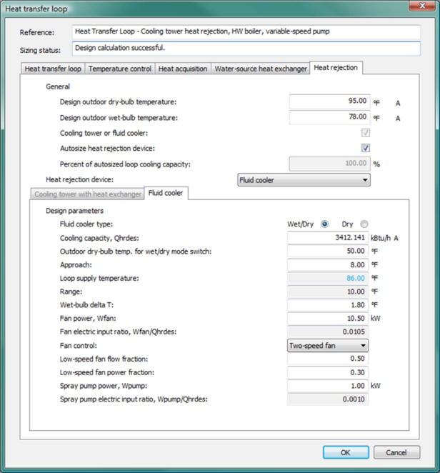
There are also heat rejection devices connected in series on the primary loop. These heat rejection devices can include: WSHX (water source heat exchanger) and cooling tower or fluid cooler. The water source heat exchanger, as noted above, can also function as a heat source. The modeling and dialog are set up to assume that the WSHX is a single device that may, if desired, operate in both heat-acquisition and heat-rejection modes. The cooling tower option comprises a separate loop with open cooling tower, water-to-water heat exchanger (WWHX), and cooling tower loop pump. The cooling tower loop is thus connected to the HTL through the WWHX, which is included to reflect the real-world need to prevent contaminants from entering the HTL. The cooling tower loop with pump and heat exchanger can alternatively be replaced with a fluid cooler, as waterside of the fluid cooler is fully contained within its integral water-to-air heat exchanger. rejecting heat to cool down the source water return temperature to source water supply temperature set point when needed.
Loop control and sequencing
The loop water returned from each of the WAHPs served by a particular heat transfer loop (each with its own return water temperature and required flow rate) is mixed at the loop return pipe to provide the overall loop return water temperature. The loop return water temperature is then compared with the target loop supply water temperature set points to determine the loop operating mode, as the following:
· If any WAHP served by a particular heat transfer loop is operating (extracting heat from or rejecting heat to the HTL), the system and loop flow will be turned on.
o If the return water temperature is lower than the loop heating supply water temperature set point, then the loop will operate in heating mode.
o If the return water temperature is higher than the loop cooling supply water temperature set point, then the loop will operate in cooling mode.
o If the return water temperature is between the loop heating and cooling supply water temperature set points, then the loop temperature will be allowed to float between these setpoints without engaging or loading any of the system-level heat acquisition or heat rejection devices.
· If no WAHP served by a particular heat transfer loop is currently operating, the loop, and hence the entire system, will remain off.
Heating mode operation
The heat acquisition sequence on a heat transfer loop, assuming all possible pre-heating devices are present, is as follows: SWH à WSHX à CHR à AWHP à CHP à Heating equipment set . Unused pre-heating devices will be skipped in the loading sequence.
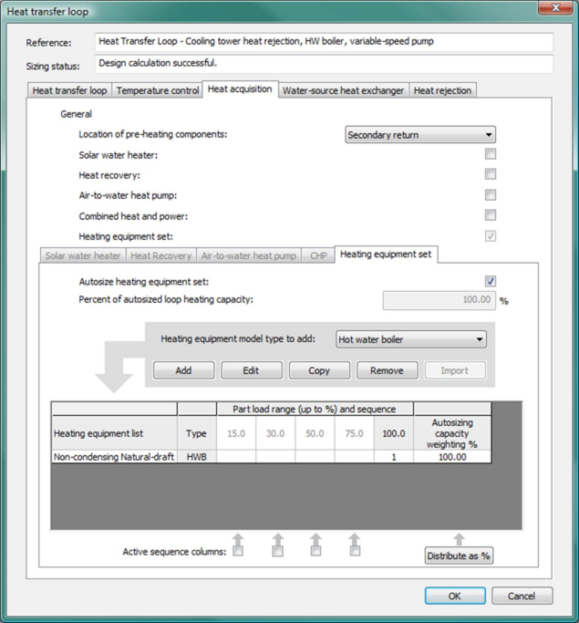
When included, the sequenced Heating equipment set associated with a heat transfer loop meets remaining load after heat available from any included solar water heater (SWH), water source heat exchanger (WSHX), condenser heat recovery (CHR), air-to-water heat pump (AWHP), or combined-heat & power (CHP) system have been fully utilized. Heat available from any of these devices (SWH, WSHX, CHR, AWHP, and CHP) is thus used to meet the load prior to engaging the sequenced equipment in the Heating equipment set (see Heating equipment set sub-tab of the Heat acquisition tab in the Heat transfer loop dialog).
Cooling mode operation
When included, the WSHX is loaded first to meet the imposed cooling load. Any load remaining after the WSHX is met by loading the available cooling tower or fluid cooler. Note that it is possible for a WSHX on a heat transfer loop to operate in both heating and cooling modes, depending on the relative temperatures of the HTL water and WSHX source water.
Loop capacity and feedback to WAHPs
If the loop heating or cooling load exceeds the combined capacity of all heating equipment and heat acquisition and rejection devices available on the loop, any deficiency in overall heat transfer loop capacity will result in a deviation of the loop supply water temperature from the loop heating or cooling supply water temperature set point. HTL supply water temperature thus provides feedback to the WAHPs. In other words, while heating or cooling sources on a Heat transfer loop will always attempt to achieve the target supply water temperature, this may not be feasible under all simulated conditions. If the target supply water temperature range on the HTL cannot be maintained, the WAHPs served must attempt to meet heating or cooling loads with cooler or warmer water.
The WAHPs served by the HTL will respond to the adjusted loop supply water temperature in its capacity and efficiency calculations, as the loop supply water temperature features as one of the independent variables in the WAHP performance curves.
Heat transfer loop sizing procedure
The sizing approach used for the heat transfer loop differs from that of the chilled water and hot water loops, which always use the chiller or heating equipment set, respectively, as the primary sizing target. The sizing approach used for the HTL is to have the user nominate the Principal equipment for sizing from amongst the heating and cooling sources on the loop, and make this the focus for sizing operations.
For heating, the Principal equipment for sizing may be a sequenced heating equipment set, a water-source heat exchanger, or an air-to-water heat pump; however, it may not be a solar water heater, which is not amenable to sizing by any simple procedure. The ‘principal equipment’ will be sized to provide the entire loop heating load (and subject to the oversizing factor in the main HTL tab). Other devices feeding heat into the loop are sized to a specified percentage of the loop heating capacity. The Current loop capacity is the heating capacity of the principal equipment (which may have been manually edited).
Cooling sizing proceeds along similar lines. Here the ‘principal equipment’ may be a cooling tower with heat exchanger, fluid cooler, or water-source heat exchanger.
Based on this approach, in the system-level ASHRAE Loads autosizing run (Analysis type = ApacheHVAC system loads), two design loads will be calculated for the heat transfer loop:
a) Design heat acquisition load for heating
b) Design heat rejection load for cooling
Firstly, the design heat acquisition load for heating and design heat rejection load for cooling will be used to update the respective Autosized loop heating and cooling capacities in the HTL tab of the HTL dialog.
Secondly, the two design loop loads are translated according to relative capacities set for the individual heating and cooling devices on the loop. Capacities are updated for the Principal equipment for sizing and for any other devices for which the Autosize… checkbox is ticked. This can be summarized as follows:
· Heat acquisition load (loop heating capacity)
o 100% + oversizing factor goes to the principal heating equipment (it will be sized to meet the entire loop heating load).
o User specified percentage × (100% + oversize factor) goes to other heat acquisition devices that are present and designated for autosizing.
· Heat rejection load (loop cooling capacity)
o 100% + oversizing factor goes to the principal cooling equipment (it will be sized to meet the entire loop heat rejection load).
o User specified percentage × (100% + oversize factor) goes to other heat rejection devices that are present and designated for autosizing.
Whether or not the capacity for an individual heating or cooling device will be updated with the autosized value depends on the status of its corresponding Autosize… checkbox. If this checkbox is ticked for a device, its capacity will be updated with the autosized value. If this checkbox is not ticked for a device, its capacity will not be updated with the autosized value.
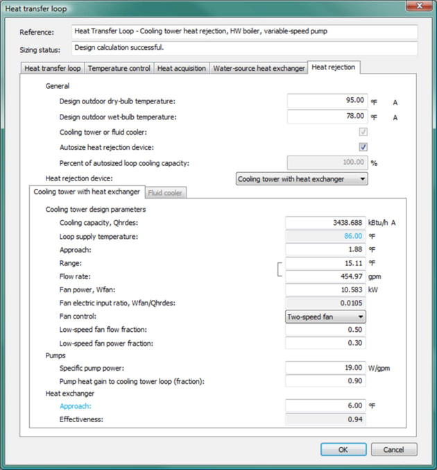
In addition to the capacities for the heat transfer loop and individual heating and cooling devices, the following two design temperatures will also be updated after a system sizing run:
· Design outdoor dry-bulb temperature on the Heat rejection tab of the HTL dialog
· Design outdoor wet-bulb temperature on the Heat rejection tab of the HTL dialog
Heat transfer loop pump modeling
As noted above, there are two options for the Heat transfer loop configuration:
· Primary-only : Loop flow is maintained by a primary pump that can be either a variable-speed pump (i.e., using a variable-speed drive) or constant-speed pump riding the pump curve.
· Primary-Secondary : Loop flow is maintained by a combination of primary and secondary pumps. The primary pump is assumed to have constant flow when it is on. The secondary pump can be either a variable-speed pump with VSD or a constant-speed pump riding the pump curve.
For both Heat transfer loop configurations, pumps are assumed to operate whenever at least one WAHP unit served by the HTL is operating—i.e., whenever there is heat rejection to or heat acquisition from the HTL . Otherwise, all pumps remain off and there is no water loop flow.
If the pump has a constant flow when it is on, as is true for the primary pump in the Primary-Secondary configuration , this constant flow is multiplied by its specific pump power to determine the pump power. If the pump has variable flow, which can be the case for the primary pump in the Primary-only configuration or the secondary pump in the Primary-Secondary configuration, i ts design pump power is calculated as the specific pump power multiplied by the design water flow rate. The design pump power is then modified by the pump power curve to get the operating pump power. If a pump has variable flow it will be subject to cycling on/off below the minimum flow rate permitted.
The variable flow featured in the pump power curve is calculated as the sum of flow required from all WAHPs served by the heat transfer loop, subject to the minimum flow permitted for the pump. Required water flow rates for the WAHPs vary in proportion to their heat rejection or heat acquisition loads.
When the Primary-only configuration is selected for the Heat transfer loop, this effectively removes the constant-speed primary loop pump from the diagram in Figure 3-35 .
Heat transfer loop distribution losses and pump heat gain
Distribution losses from the pipe work are considered as a user-specified percentage of the heat transfer loop load. Transfer of loop pump heat gain to the loop is modeled according to a user input fraction for pump and motor heat gain to the heat transfer loop.
Heat transfer loops dialog
The heat transfer loops tool provides access to adding, editing, copying, and removing named heat transfer loops.

Toolbar button for Heat transfer loops .
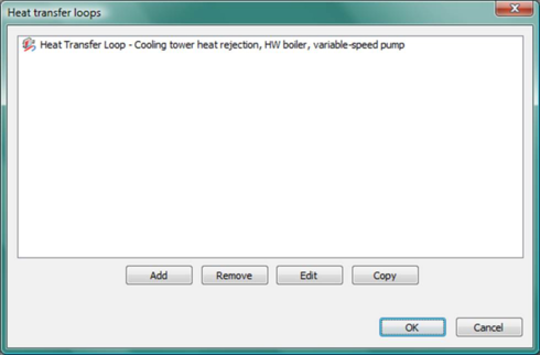
Clicking this toolbar button opens up the Heat transfer loops dialog (shown in Figure 2-36), which manages the list of heat transfer loops . A heat transfer loop may be added, edited, removed, or copied through the corresponding buttons in this dialog. Double clicking on an existing heat transfer loop, or clicking the Edit button after selection of an existing heat transfer loop , opens the Heat transfer loop dialog (shown in Figure 2-37) where parameters for the selected loop may be edited.
Figure 3 - 36 : Heat transfer loops dialog shown with illustrative default loop included with the pre-defined systems in VE 2012 (v6.5).
Heat transfer loop dialog
The Heat transfer loop dialog has five tabs:
· Heat transfer loop : This tab manages the properties of the heat transfer loop. It provides inputs for the loop principle equipment for sizing, information on loop capacity and flow, as well as inputs for the primary and secondary loop pumps.
· Temperature control : This tab provides inputs for the loop temperature controls.
· Heat acquisition : This tab manages information used for all devices available for adding heat to the loop (SWH, CHR, AWHP, CHP, and Heating equipment set), except for the WSHX, which can be used as both heating and cooling source and is presented on its own in a separate tab.
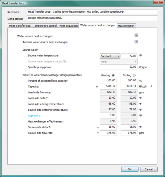
· Water-source heat exchanger : This tab provides inputs for the WSHX, which can be used to add heat to or reject heat from the loop.
· Heat rejection : This tab manages information used for heat rejection devices (cooling tower or fluid cooler) on the loop, except the WSHX, which can be used as both heating and cooling source and is presented on its own in a separate tab.
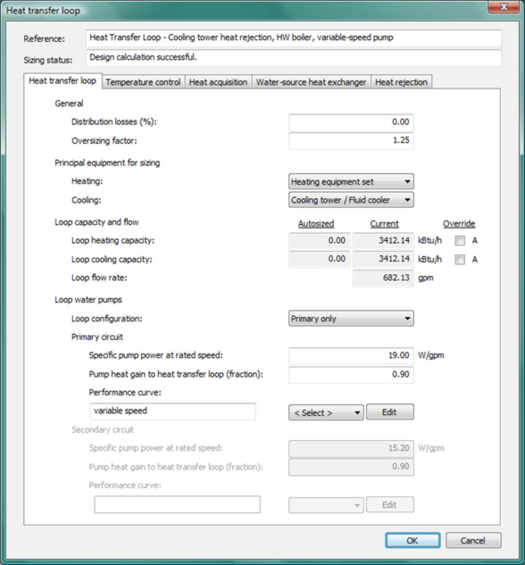
Figure 3 - 37 : Heat transfer loop dialog shown with the Heat transfer loop tab selected.
Reference name for Heat transfer loop
Enter a description of the component to aid in selecting and referencing any component or controllers within other dialogs and in the component browser tree. Reference names should be informative with respect to differentiating similar equipment, components, and controllers.
Sizing status
The sizing status is an informative field indicating whether the design calculation is feasible for the current settings of all relevant heat transfer loop input parameters.
The sizing status is checked and updated instantaneously in response to any changes on the parameters that the following derived parameters depend upon, provided that these derived parameters are active (enabled):
a) Loop flow rate in the HTL tab
b) HX design approach and design effectiveness in the WSHX tab
c) Fluid cooler or cooling tower design approach in the Heat rejection tab
d) Cooling tower HX design approach and design effectiveness in the Heat rejection tab
For the above derived parameters to be considered as feasible:
a) HTL loop flow rate should be > 0.0;
b) WSHX design approach should be ≥ 0.0 K;
c) WSHX design effectiveness (ɛ) should be: 0.0 ≤ ɛ ≤ 1.0;
d) Fluid cooler design approach should be ≥ 0.01 K;
e) Cooling tower design approach should be ≥ 0.01 K;
f) Cooling tower HX design approach should be ≥ 0.0 K;
g) Cooling tower HX design effectiveness (ɛ) should be: 0.0 ≤ ɛ ≤ 1.0;
When an individual derived parameter is feasible, it is displayed in black text. When all of the above derived parameters are feasible, the sizing status field displays “Design calculation successful.”
If any of the above derived parameters is infeasible (out of range), the infeasible derived parameter is displayed (on the interface) in red text, and the sizing status field displays “Design calculation failed. The parameters in red are out of range.” in red text.
Heat transfer loop tab
The Heat transfer loop tab facilitates the definition of the loop principle equipment for sizing, loop capacity and flow, the primary and secondary loop pumps, together with the distribution losses and oversizing factor for the heat transfer loop.
Distribution Losses
Enter the heat transfer loop distribution losses—i.e., the loss due to distribution of heating or cooling from the heating or cooling plant to point of use—as a percentage of heating or cooling demand. The loss entered here does not accrue to the conditioned spaces within the building. Rather, this heat is assumed to be lost either directly or indirectly to the outdoor environment.
|
Warning Limits (%)
|
0.0 to 20.0
|
|
Error Limits (%)
|
0.0 to 75.0
|
Oversizing Factor
Following system-level autosizing, the factor by which the heating or cooling plant equipment size is increased relative to the peak value occurring during the sizing run.
Principal equipment for sizing
Select the principle equipment for sizing, both for heating/heat acquisition and for cooling/heat rejection. To ensure there is always at least one device available to add required heat the heat transfer loop and to reject excess heat from the loop, a principle device for heating and cooling must be selected. This selection will, in turn, force at least one device to be defined for each of these roles.
There are three options for the principle heating device:
· Heating equipment set
· Water-source heat exchanger
· Air-to-water heat pump.
There are three options for the principle cooling device:
· Cooling tower/Fluid cooler
· Water-source heat exchanger
Except for the case of the Override checkbox beside the Current loop capacities (see below in the loop capacity section) is ticked, the capacities of the principal devices are the basis for the Current loop capacities and loop flow rate derivation. In other words, when the Override checkbox is not ticked, the Current loop capacities (heating and cooling) are dynamic copies of the capacities of the principal devices, and these may or may not have been updated by autosizing.
When the Override checkbox is ticked, the corresponding Current loop capacity becomes an input field, which allows values for Loop heating capacity or Loop cooling capacity to be overridden by a manual edit. Once overridden, the Current loop capacities, and hence the loop flow rate, are decoupled from the capacities of the principle device(s).
Tip: After completing a system sizing with one principle device selected, ticking the Override checkbox and switching the principle device from the pre-sizing selection to another one provides the opportunity to turn off the pre-sizing principle device in further simulations.
When a Heating equipment set is the principal heating device, capacity is given by the sum of the design heating capacities for equipment with nonzero sequencing rank in the rightmost column of the sequencing table in the Heating equipment set sub-tab of the Heat acquisition tab.
Whether or not an individual heating or cooling device on the loop will be autosized after a system sizing run, regardless of principle or non-principle status for sizing, depends on the status of its Autosize checkbox (see below). If the Autosize… checkbox for an individual device is ticked, its capacity will be updated after autosizing. Otherwise, its capacity will remain at the pre-sizing value.
If an individual device is designated as the Principle equipment for sizing, and its Autosize checkbox is ticked, then upon autosizing the peak Heat transfer loop heating or cooling capacity determined by autosizing will be used directly to update the capacity of this individual device. In other words, a principle device with its Autosize checkbox ticked will always get 100% of the autosized loop heating or cooling capacity, after consideration of the oversizing factor.
If an individual device is not the current principle device for sizing, and its Autosize checkbox is ticked, then upon autosizing the peak Heat transfer loop heating or cooling capacity determined by autosizing will be multiplied by its Percent of autosized loop heating or cooling capacity (see below) to determine its capacity. The resultant capacity will then be used to update the capacity of this individual device. In other words, a non-principle device with its Autosize checkbox ticked will get a percentage of the autosized loop heating or cooling capacity as specified by its Percent of autosized loop heating or cooling capacity, after consideration of the oversizing factor. In this case, the capacity fraction assigned to the non-principle device is not subtracted from the loop heating or cooling capacity.
Also, for a non-principle device with its Autosize checkbox ticked, once the heat transfer loop has been sized, edits made in its Percent of autosized loop heating or cooling capacity (%) field will lead to automatic dynamic updating of its capacity, based on the autosized loop heating or cooling capacity.
Loop capacity and flow
The Autosized loop capacities (for heating and cooling) are un-editable fields, which are initialized to zero and subsequently display the results from the most recent system auto-sizing analysis.
When the ‘Override’ checkbox besides the Current loop capacities is not ticked, the Current loop capacities (heating and cooling) are dynamic copies of the capacities of the principal devices (which may or may not have been updated by auto-sizing).
Ticking the ‘Override’ checkbox allows the Current value of the Loop heating or cooling capacity to be overridden by a manual edit (otherwise all these values are un-editable).
When the ‘Override’ box is ticked, after autosizing, the Current value of the associated capacity remains at the user-specified value. This value is not dynamically linked to the principle equipment sizes.
Loop flow rate is derived dynamically from the Current loop capacity values, taken together with loop temperature delta-T parameters specified in the ‘Temperature control’ tab. The loop flow rate feeds into dynamic parameter derivations for certain components on the loop (cooling tower, fluid cooler, water-source heat exchanger, etc.).
Capacities for individual heating and cooling devices can be edited manually, overriding autosized values for the equipment. In the case of principal equipment for sizing, when the ‘Override’ box is not ticked, user edits made in the principal equipment capacity will feed back to the Current value of Loop capacities. This may cause a change to Loop flow rate, which may in turn cause changes to dynamically derived parameters for other devices on the loop.
Loop Configuration
Select the loop configuration. Two options are offered: Primary-only and Primary-Secondary.
Primary Circuit Specific Pump Power at Rated Speed
Enter the primary circuit specific pump power at rated speed, expressed in W/(l/s) in SI units (or W/gpm in IP units).
If the ‘loop configuration’ is selected as Primary-only:
Primary circuit pump power will be calculated on the basis of variable flow, subject to the constraint that the pump will start cycling below the minimum flow rate it permits. The operating pump power will be based on its design pump power modified by the pump power curve. Its design pump power is calculated as the specific pump power multiplied by the design water flow rate. The default value for the specific pump power in this case is the total specific pump power (19 W/gpm) as specified in ASHRAE 90.1 G3.1.3.5.
The required variable flow featured in the pump power curve is calculated as the summation of required flow from all components (WAHPs) served by the heat transfer loop, subject to the minimum flow the pump permits. Required loop water flow rates for WAHPs vary in proportion to their heat rejection or heat acquisition loads.
If the ‘loop configuration’ is selected as Primary-Secondary:
Primary circuit pump power will be calculated on the basis of constant flow (when it operates). The model will be based on a specific pump power parameter, with a default value of 3.8 W/gpm. The default value is based on the total specific pump power (19 W/gpm) as specified in ASHRAE 90.1 G3.1.3.5 and assuming a 20:80 split between the primary and secondary circuits.
The primary circuit loop flow rate will be calculated from the Current loop capacity values, taken together with loop temperature delta-T parameters specified in the ‘Temperature control’ tab.
Primary Circuit Pump Heat Gain to Heat Transfer Loop (fraction)
Enter the primary circuit pump heat gain to heat transfer loop, which is the fraction of the motor power that ends up in the loop water. Its value is multiplied by the primary circuit pump power to get the primary circuit pump heat gain, which is added to the loop cooling load or deducted from the loop heating load.
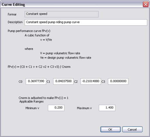
Primary Circuit Pump Power Curve, fPv(v)
This field is only active when the ‘loop configuration’ is selected as Primary-only.
If this field is active:
This is the primary circuit pump power curve currently selected. Use the Select button to select the appropriate curve from the system database. Use the Edit button to edit the curve parameters if you like. The Edit button will pop up a dialog displaying the formula and parameters of the curve, allowing the curve parameters to be edited. You are allowed to edit the curve coefficients, in addition to the applicable ranges of the curve independent variables. When editing the curve parameters, it is important that you understand the meaning of the curve and its usage in the model algorithm.
Also be careful that the edited curve has reasonable applicable ranges for the independent variables. A performance curve is only valid within its applicable ranges. In the case the independent variables are out of the applicable ranges you set, the variable limits (maximum or minimum) you specified in the input will be applied.
The primary circuit pump power curve f Pv (v) is a cubic function of
v = V/V e
where
V = pump volumetric flow rate.
V e = design pump volumetric flow rate.
And:
f Pv (v) = (C 0 + C 1 v + C 2 v 2 + C 3 v 3 ) / C norm
where
C 0 , C 1 , C 2 and C 3 are the curve coefficients
C norm is adjusted (by the program) to make f Pv (1) = 1
The primary circuit pump power curve is evaluated for each iteration of the heat transfer loop, for each time step during the simulation. The curve value is multiplied by the design primary pump power to get the operating primary pump power of the current time step, for the current fraction of pump volumetric flow rate. The curve should have a value of 1.0 when the operating pump volumetric flow rate equals rated pump volumetric flow rate (v = 1.0).
Figure 3 - 38 : Edit dialog for the primary circuit pump power curve (values for constant-speed pump are shown)
Secondary Circuit Specific Pump Power at Rated Speed
This field is only active when the ‘loop configuration’ is selected as Primary-Secondary.
If this field is active:
Enter the secondary circuit specific pump power at rated speed, expressed in W/(l/s) in SI units (or W/gpm in IP units). The default value (15.2 W/gpm) is based on the total specific pump power (19 W/gpm) as specified in ASHRAE 90.1 G3.1.3.5 and assuming a 20:80 split between the primary and secondary circuits.
Secondary circuit pump power will be calculated on the basis of variable flow, subject to the constraint that the pump will start cycling below the minimum flow rate it permits. The operating pump power will be based on its design pump power modified by the pump power curve.
Its design pump power is calculated as the specific pump power multiplied by the design loop flow rate. The design secondary circuit loop flow rate is assumed equal to the design primary circuit loop flow rate, which is calculated from the Current loop capacity values, taken together with loop temperature delta-T parameters specified in the ‘Temperature control’ tab.
The required variable flow featured in the pump power curve is calculated as the summation of required flow from all components (WAHPs) served by the heat transfer loop, subject to the minimum flow the pump permits. Required loop flow rates for WAHPs vary in proportion to their heat rejection or heat acquisition loads.
Secondary Circuit Pump Heat Gain to Heat Transfer Loop (fraction)
This field is only active when the ‘loop configuration’ is selected as Primary-Secondary.
If this field is active:
Enter the secondary circuit pump heat gain to heat transfer loop, which is the fraction of the motor power that ends up in the loop water. Its value is multiplied by the secondary circuit pump power to get the secondary circuit pump heat gain, which is added to the loop cooling load or deducted from the loop heating load.
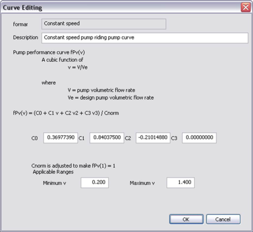
Secondary Circuit Pump Power Curve, fPv(v)
This field is only active when the ‘loop configuration’ is selected as Primary-Secondary.
If this field is active:
This is the secondary circuit pump power curve currently selected. Use the Select button to select the appropriate curve from the system database. Use the Edit button to edit the curve parameters if you like. The Edit button will pop up a dialog displaying the formula and parameters of the curve, allowing the curve parameters to be edited. You are allowed to edit the curve coefficients, in addition to the applicable ranges of the curve independent variables. When editing the curve parameters, it is important that you understand the meaning of the curve and its usage in the model algorithm.
Also be careful that the edited curve has reasonable applicable ranges for the independent variables. A performance curve is only valid within its applicable ranges. In the case the independent variables are out of the applicable ranges you set, the variable limits (maximum or minimum) you specified in the input will be applied.
The secondary circuit hot water pump power curve f Pv (v) is a cubic function of
v = V/V e
where
V = pump volumetric flow rate.
V e = design pump volumetric flow rate.
and
f Pv (v) = (C 0 + C 1 v + C 2 v 2 + C 3 v 3 ) / C norm
where
C 0 , C 1 , C 2 and C 3 are the curve coefficients
C norm is adjusted (by the program) to make f Pv (1) = 1
The secondary circuit pump power curve is evaluated for each iteration of the heat transfer loop, for each time step during the simulation. The curve value is multiplied by the design secondary pump power to get the operating secondary pump power of the current time step, for the current fraction of pump volumetric flow rate. The curve should have a value of 1.0 when the operating pump volumetric flow rate equals rated pump volumetric flow rate (v = 1.0).
Figure 3 - 39 : Edit dialog for the secondary circuit pump power curve (values for constant-speed pump are shown)
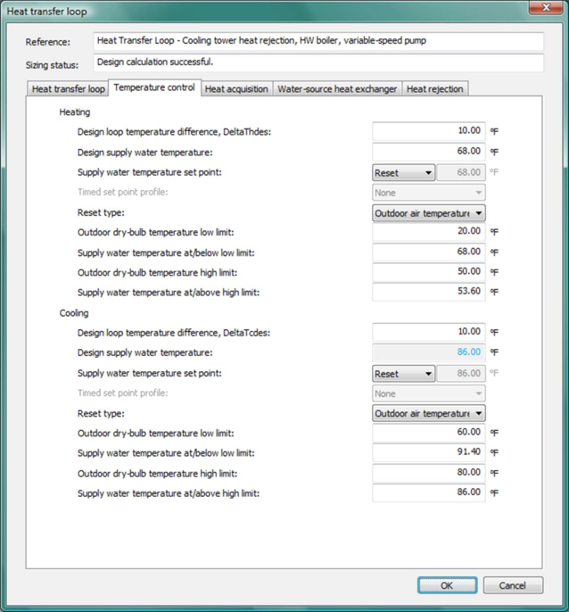
Temperature control tab
The Temperature control tab provides inputs for the heat transfer loop temperature controls. There are two parallel sets of temperature control parameters provided in this tab: one set for heating, one set for cooling. The descriptions below for each of these temperature control parameters apply to both heating and cooling temperature controls.
Figure 3 - 40 : Temperature control tab on Heat transfer loop dialog.
Design Loop Temperature Difference, DeltaThdes & DeltaTcdes
Enter the design loop temperature difference for heating and cooling, i.e., the difference between the design loop supply water temperature and return water temperature.
Design Supply Water Temperature
For heating, the design loop supply water temperature may be either an input field or a derived parameter (un-editable field with a grey background), depending on the currently selected heating principle equipment for sizing (in the Heat transfer loop tab). If this is an input field, enter the desired design loop supply water temperature for heating. If this is a derived parameter, then the heating design loop supply water temperature is determined by parameter inputs for the currently selected heating principle equipment for sizing, and does not need to be entered in the Temperature control tab.
For cooling, the design loop supply water temperature currently is always a derived parameter (un-editable field with a grey background), and does not need to be entered in the Temperature control tab. It is determined by parameter inputs for the currently selected cooling principle equipment for sizing, which may be either Cooling tower/Fluid cooler or WSHX.
The default values for heating and cooling design supply water temperatures are taken as the rated WAHP entering fluid temperatures from ANSI/ARI/ASHRAE ISO Standard 13256-1: 1998.
Supply Water Temperature Set Point
Three options are available for heating and cooling supply water temperature set point: Constant, Profiled, or Reset.
Whichever option is selected, to avoid the heating and cooling set point compete each other on the loop temperature control at the same time step during a simulation, please ensure that the heating supply water temperature set point is not higher than the cooling supply water temperature set point at the same time step during a simulation. Otherwise, an error will be reported and the simulation will not be able to proceed.
The software provides a check on this when it is possible, i.e., when both heating and cooling set points are specified as Constant. For all other cases, it is your responsibility to avoid the heating and cooling set point compete each other on the loop temperature control at the same time step during a simulation.
Constant Supply Water Temperature Set Point
When Constant is selected for heating and cooling supply water temperature set point, enter the desired constant heating and cooling loop supply water temperature set point.
Timed Supply Water Temperature Set Point Profile
When Profiled is selected for heating and cooling supply water temperature set point, select the absolute profile to be applied to the loop supply water temperature set point, which are defined through the APPro facility (the Profiles Database).
Supply Water Temperature Reset Type
When Reset is selected for heating and cooling supply water temperature set point, select the supply water temperature reset type. Currently only one option is provided: Outdoor air temperature reset . When Outdoor air temperature reset type is selected, which is the default, you also need to specify four more reset parameters:
· Outdoor dry-bulb temperature low limit
· Supply water temperature at or below low limit
· Outdoor dry-bulb temperature high limit
· Supply water temperature at or above high limit
Outdoor Dry-bulb Temperature Low Limit
When heating or cooling supply water temperature reset type is selected as Outdoor air temperature reset, enter the outdoor dry-bulb temperature low limit to be used by the reset.
Supply Water Temperature at or below Low Limit
When heating or cooling supply water temperature reset type is selected as Outdoor air temperature reset, enter supply water temperature at or below the outdoor dry-bulb temperature low limit, to be used by the reset.
Outdoor Dry-Bulb Temperature High Limit
When heating or cooling supply water temperature reset type is selected as Outdoor air temperature reset, enter the outdoor dry-bulb temperature high limit to be used by the reset.
Supply Water Temperature at or above High Limit
When heating or cooling supply water temperature reset type is selected as Outdoor air temperature reset, enter the supply water temperature at or above the outdoor dry-bulb temperature high limit, to be used by the reset.
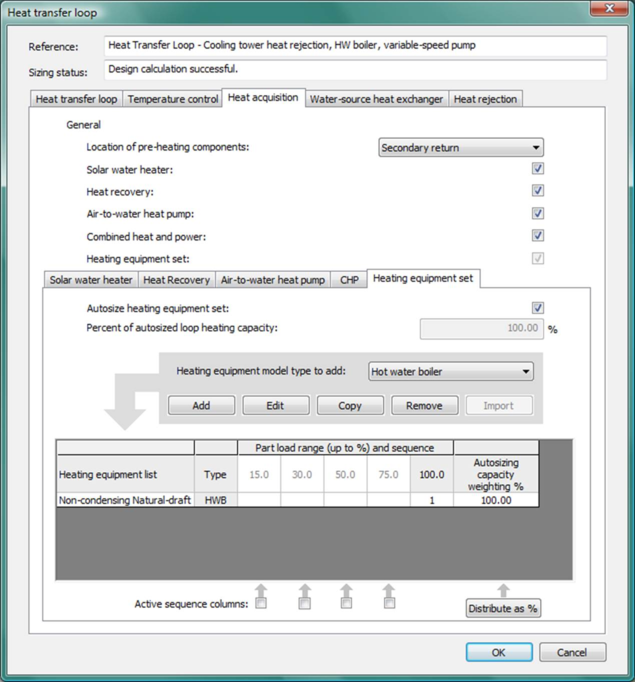
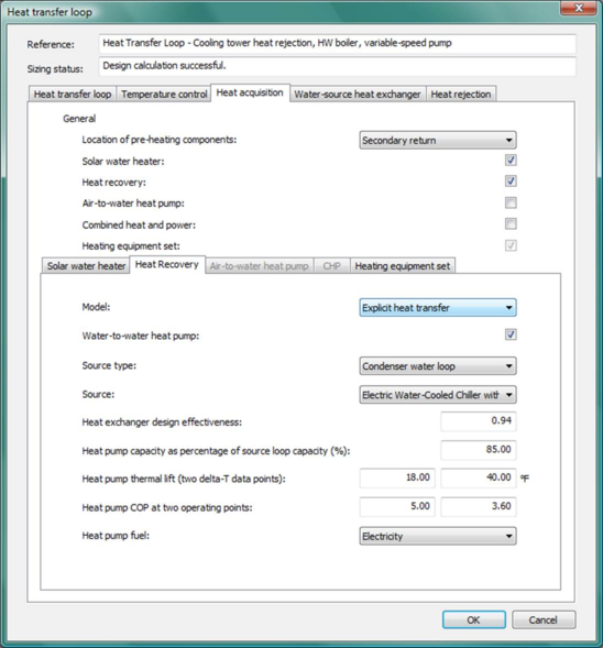
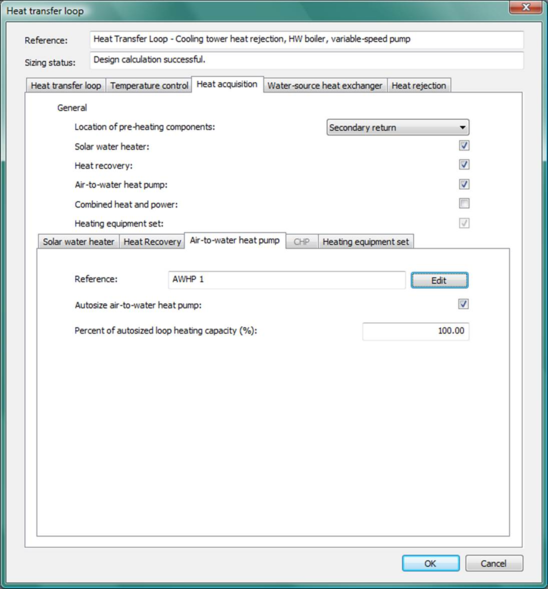
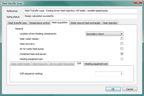
Heat acquisition tab
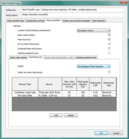
The Heat acquisition tab manages information used for all possible heating devices (SWH, CHR, AWHP, CHP, heating equipment set) on the loop, except for the WSHX, which can be used as both heating and cooling source and is presented in its own separate tab. For each of the possible heating devices presented in this tab, there is a corresponding checkbox and an associated sub-tab. Ticking or un-ticking a checkbox will enable or disable the associated sub-tab. The hard-wired sequence for heat acquisition on a heat transfer loops is SWH à WSHX à CHR à AWHP à CHP à Heating equipment set .
Figure 3 - 41 : Heat acquisition tab on Heat transfer loop dialog (shown with the Heating equipment set sub-tab selected).
Location of Pre-heating Components
Select the Location of pre-heating components on the heat transfer loop. Currently only one option is provided: Secondary return.
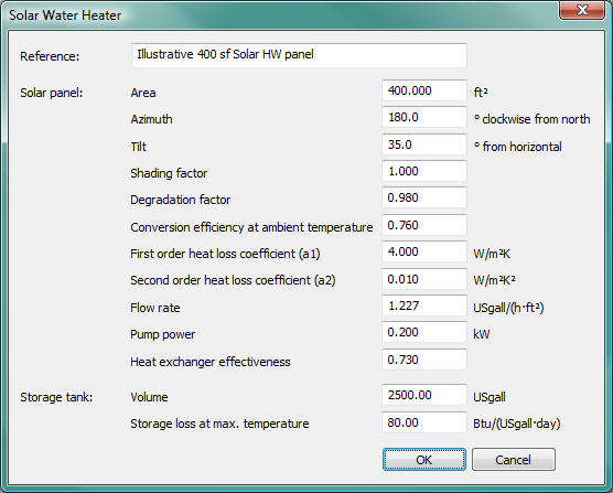
Solar water heater
Solar water heater can be used as a pre-heating device on a heat transfer loop. When present, the solar water heater will be the first-loaded device to cover heating load imposed on the heat transfer loop. Solar water heater on a heat transfer loop is modeled and functions in exactly the same manner as the Solar water heater on the hot water loop (see section 3.3.5 Solar Water Heater).
Figure 3 - 42 : Solar water heater dialog with illustrative inputs.
Solar water heater checkbox
Tick this checkbox to specify a solar water heater as a pre-heating device on the heat transfer loop. Ticking or un-ticking this checkbox will enable or disable the associated Solar water heater sub-tab below.
Solar water heater reference
This displays the Reference name of the solar water heater associated with this heat transfer loop. It is not editable directly in the HTL dialog and should be edited in the solar water heater dialog, which is opened by clicking the ‘Edit’ button to the right of this field.
Heat recovery
Heat recovery, when enabled within the Heat transfer loop dialog, serves heat acquisition loads ahead after any solar water heating and/or water-source heat exchanger. The hard-wired sequence for heat acquisition on a heat transfer loops is SWH à WSHX à CHR à AWHP à CHP à Heating equipment set . The heat recovery can be modeled as either a heat exchanger or water-to-water heat pump between loops. Most often, but not always, the recovered heat is from a condenser water loop for cooling equipment, and in that case referred to as condenser heat recovery (CHR).
There are two heat exchanger and water-water heat pump (WWHP) model options for heat recovery when the recipient is a Hot water loop: a simple fixed-percentage effectiveness heat exchanger and fixed-COP heat pump or an explicit model with heat exchanger effectiveness and heat pump COP varying according to the loop water temperatures.
· Percentage of heat rejection heat-exchanger model
This simple heat-exchanger model is essentially the same as the heat recovery model provided in pre-v6.5 versions. It models the heat recovery as a simple percentage of the source heat rejection. The percentage represents a fixed heat-exchanger effectiveness.
· Fixed-COP water-source heat pump model
The temperature for the recovered heat can be upgraded with a water-to-water or water-source heat pump (WSHP)—e.g., from 90°F to 140°F. This would typically be used when serving space-heating loads such as direct (DX-based) heating of supply air or hot water for heating coils and baseboard heaters that require higher temperatures than normally available via a simple heat exchanger on the condenser water loop. The Percentage of heat rejection model can be used regardless of whether there is an explicit modeling of the loop water temperatures on the heat recovery source and recipient sides.
· Explicit heat transfer :
This option models the heat transfer between the heat recovery source and recipient loops using an explicit water-to-water heat exchanger, which modulates the heat exchanger effectiveness for off-design temperature differences across the heat exchanger.
· Variable-COP water-source heat pump model
In the explicit heat transfer model, the water-to-water heat pump (WWHP) used to upgrade recovered heat modulates COP in response to the temperature difference or “thermal lift” between the heat recovery source loop and the heat recovery recipient loop at each simulation time step. This relatively simple model uses linear interpolation to vary the COP between two user-input COP values corresponding to two heat pump operation points (low & high thermal lift). The Explicit heat transfer model can be used only when there is an explicit modeling of the loop water temperatures on the heat recovery source and recipient sides.
Capacity for the Heat Recovery WWHP is now limited to a user-specified percentage of the heat recovery source capacity, whereas in pre-v6.5 versions WWHP capacity was a percentage of the instantaneous load on the source. This revised limit has been introduced in both of the WWHP models described above in order to provide a more realistic basis for the capacity. This avoids recovering more heat with the WWHP than would be possible (or desirable) in practice. Without this constraint the WWHP could entirely displace the boilers on a HWL, which might not be what the user intends or expects.
Heat recovery sources and recipients
All heat recovery data are now displayed, edited, and stored on the recipient side ( Chiller Model Description
Clicking this button provides a summary of electric water-cooled chiller model variables as shown below:
Figure 3-97: Electric water-cooled chiller model description
Figure 3-98 and Figure 3-17 below).
Heat recovery sources can be either a part-load-curve “chiller” model (which may represent something other than a water-cooled chiller) or a condenser water loop serving one or more electric water-cooled chillers. Future versions will expand on the range of possible sources, for example, allowing the heat-transfer loop to be selected as a source. Heat recovery recipients can be a generic heat source, a hot water loop, or a heat transfer loop.
When the Percentage of heat rejection model is used, there can be multiple heat recovery sources linked to one recipient. This is among the reasons that the sources are now specified in the recipient dialog. Source types can be any combination of condenser water loops and/or part-load curve chiller models. Each heat recovery source can be linked to just one heat recipient.
When the Explicit heat transfer model is used, there can be only one heat recovery source linked to a given recipient loop, and the source type is limited to condenser water loops.
The heat recovery recipient is displayed on the source side (Heat recovery sub-tab within the Heat Rejection tab of the Chilled water loop dialog and in the Part-load curve chiller model dialog) for user’s information only. Each heat recovery source can be linked to only one heat recovery recipient.
Figure 3 - 43 : Heat Recovery sub-tab on the Heat acquisition tab within the Heat transfer loop dialog (top) using the Percentage of heat rejection model with water-to-water heat pump and illustrative inputs for source, percentage heat recovery, and WWHP performance. Also shown (below the Hot water loop dialog), the Condenser heat recovery recipient designation is displayed within the Heat rejection tab of the Chilled water loop dialog.
Figure 3 - 44 : Heat Recovery tab within the Heat transfer loop dialog (top) using the Explicit heat transfer model with water-to-water heat pump and illustrative inputs for source, heat exchanger effectiveness, and WWHP performance. Also shown (below the Hot water loop dialog), the Condenser heat recovery recipient designation is displayed within the Heat rejection tab of the Chilled water loop dialog.
Heat recovery checkbox
Tick this checkbox to specify heat recovery as a heat source on the heat transfer loop. Ticking or un-ticking this checkbox will enable or disable the associated heat recovery sub-tab below.
Heat recovery model
Choose the desired heat recovery model type. Two model types are provided: Percentage of heat rejection and Explicit heat transfer.
If Percentage of heat rejection is selected, you will be able to specify multiple heat recovery sources contributing to the same hot water loop (the heat recovery recipient), listed in a source table below, together with other parameters required by the Percentage of heat rejection model. For each heat recovery source row in the table, these column fields are displayed: Source type, Source, Max. heat recovery with HX (%, as percentage of source loop load), Heat pump capacity (%, as percentage of source loop capacity), Heat pump COP, and Heat pump fuel. In this case, a heat recovery source can be added or removed using the Add or Delete button below the source table. Double clicking any active cell within the source table provides editing access to that specific cell.
If Explicit heat transfer is selected, you will be able to specify only one heat recovery source contributing to the hot water loop (the heat recovery recipient), together with other parameters required by the Explicit heat transfer model.
Water-to-water heat pump checkbox
The heat recovered from the heat recovery source(s) may be upgraded using a water-to-water heat pump (See additional explanation above). Specify this mode of operation by ticking the Water-to-water heat pump checkbox.
Source type
Choose the heat recovery source type for a particular source.
For the Percentage of heat rejection model, Source type is listed in the first column of the source table. Double clicking a cell in this column allows you to choose the source type from two options: Condenser water loop or Part load chiller.
For the Explicit heat transfer model, Source type is selected from the Source type combo box, currently with one available option: Condenser water loop.
When source type is Condenser water loop, this is referring to a condenser water loop associated with a currently defined chilled water loop.
When source type is Part load chiller, this is referring to any currently defined part load chiller either on a chilled water loop or separately defined as a Generic cooling source.
Source
Choose the heat recovery source name for a particular source.
For the Percentage of heat rejection model, Source is listed in the second column of the source table. Double clicking a cell in this column allows you to choose the source from a drop-down list of available sources currently defined in the HVAC system file.
For the Explicit heat transfer model, use the Source drop-down list on the right hand side of the dialog to select from available sources currently defined in the HVAC system file.
Note that for both heat recovery models, only the current available sources defined in the HVAC file will be included in the drop-down list:
· If the selected Source type is Condenser water loop, ‘available’ means the listed chilled water loop has a condenser water loop (Condenser water loop box on Heat rejection tab is ticked) that has not been specified as a heat recovery source for any other heat recovery recipient.
· If the selected Source type is Part-load chiller, ‘available’ means the defined part-load chiller has not been specified a heat recovery source for any other heat recovery recipient.
On switching the model option from Percentage of heat rejection to Explicit heat transfer, no more than one source will remain active and displayed (and this must not be a part load curve chiller). If there are multiple sources specified prior to the switch and these include more than one valid source for the Explicit heat transfer option, then the first valid source for the Explicit heat transfer option will remain; other specified sources will be removed. If prior to the switch, there are only part load curve chillers specified as sources, then upon switching the Source combo list will be set to <None>.
For a specified heat recovery source, its recipient will be displayed in the corresponding source dialog for user’s information only.
Max. heat recovery with HX (%)
This parameter is only required by the Percentage of heat rejection model. When Percentage of heat rejection model is used, this field (in the 3rd column of the source table) represents the percentage of the source heat rejection (from either a condenser water loop or a part load chiller) that is subject to heat recovery using a heat exchanger.
In this case, the amount of heat recovered at any given time is given by:
Where, Ql is the load on the electric water-cooled chiller(s) if the heat recovery source is a condenser water loop (or the load on the part load curve chiller if the source is from a part load chiller), Qc is the compressor power for the chiller(s) and p is heat recovery percentage.
Heat exchanger design effectiveness
This parameter is only required by the Explicit heat transfer model. When Explicit heat transfer model is used, it represents the design effectiveness of the water-to-water heat exchanger used for heat recovery purpose.
Heat pump capacity (%)
This field is only enabled when the Water-to-water heat pump checkbox is ticked, i.e., when a water-to-water heat pump is used to upgrade the heat recovered from the source(s). When active, enter the capacity for the desired water-to-water heat pump, as a percentage of the source loop capacity. This is used to limit the capacity of the water-to-water heat pump. When heat recovery source is a condenser water loop: the source loop capacity is the cooling tower or fluid cooler capacity (the condenser water loop capacity). When heat recovery source is a part load chiller: the source loop capacity is the part load chiller heat rejection capacity.
For the Percentage of heat rejection model, heat pump capacity is listed in the 4th column of the source table. Double clicking a cell in this column allows you to manually edit its value.
For the Explicit heat transfer model, heat pump capacity can be edited in the named field.
Heat pump COP
This field is only enabled when the Water-to-water heat pump checkbox is ticked, i.e., when a water-to-water heat pump is used to upgrade the heat recovered from the source(s). When active, enter the COP(s) for the desired water-to-water heat pump.
For the Percentage of heat rejection model, heat pump COP is listed in the 5th column of the source table. Double clicking a cell in this column allows you to manually edit its value, which should normally be the COP for this equipment when the source loop and recipient loop are at design temperatures; however, this may differ for some system designs. In this case, the specified COP is applied as a constant for a WWHP coupled to a specific heat recovery source during simulation.
For the Explicit heat transfer model, heat pump COP can be edited in the named field at two operating points corresponding to the two Heat pump thermal lifts (two delta-T data points) that you could specify (see below). In this case, instead of using a constant COP for the WWHP, the WWHP COP will be made responsive to the thermal lift between the heat recovery source loop and the heat recovery recipient loop during the simulation: linear interpolation will be applied to 1/COP using the two heat pump COP values corresponding to the two specified operation points (low, high).
Heat pump thermal lift (two delta-T data points)
This field is only required by the Explicit heat transfer model, and is only enabled when the Water-to-water heat pump checkbox is ticked, i.e., when a water-to-water heat pump is used to upgrade the heat recovered from the source(s). When active, enter the two heat pump thermal lifts (two delta-T data points: low, high) for the desired water-to-water heat pump. The thermal lift of the WWHP is the difference between the heat recovery source-side loop temperature before heat pump heat recovery and the recipient-side loop water temperature after heat recovery (which will ideally be the target supply water temperature of the recipient loop). During simulation, linear interpolation will be applied to 1/COP using the two heat pump COP values (see above) corresponding to the two specified thermal lifts (low, high).
Heat pump fuel
This field is only enabled when the Water-to-water heat pump checkbox is ticked, i.e., when a water-to-water heat pump is used to upgrade the heat recovered from the source(s). When active, select the fuel, type of energy source, or energy end-use category for the water-to-water heat pump. For scratch-built systems, this will normally be Electricity and for pre-defined systems this is set to Heating (electricity), which is an end-use designation for the ASHRAE 90.1 Performance Rating Method reports.
For the Percentage of heat rejection model, heat pump fuel is listed in the last column of the source table. Double clicking a cell in this column allows you to choose the heat pump fuel for the desired water-to-water heat pump coupled to a specific heat recovery source.
For the Explicit heat transfer model, heat pump fuel can be selected through the named field.
Air-to-water heat pump
An Air-to-water heat pump (AWHP) can be used as a heating device on the heat transfer loop. When present, the Air-to-water heat pump will be the first in line to meet loop heating load. The following loading sequence is pre-set for all heat transfer loops: SWH à WSHX à CHR à AWHP à CHP à Heating equipment set .
Figure 3 - 45 : Heat acquisition tab on Heat transfer loop dialog (shown with the Air-to-water heat pump sub-tab selected).
Air-to-water heat pump checkbox
Tick this checkbox to specify an Air-to-water heat pump as a heating device on the heat transfer loop. Ticking or un-ticking this checkbox will enable or disable the associated Air-to-water heat pump sub-tab below.
If the Air-to-water heat pump is selected as the heating principal equipment for sizing, this checkbox is automatically ticked and is not allowed to be un-ticked.
The input parameters for Air-to-water heat pumps are described in section 3.6.2
Air-to-water heat pump reference
This displays the reference name of the Air-to-water heat pump associated with this heat transfer loop. It is not editable directly in the HTL dialog and should be edited in the Air-to-water heat pump dialog, which is opened by clicking the Edit button to the right of this field. The input parameters for Air-to-water heat pumps are described in section 3.6.2
The Edit button opens the Air-to-water heat pump dialog.
Figure 3 - 46 : Air-to-water heat pump dialog with illustrative inputs (described in section 3.6.2 ).
Autosize air-to-water heat pump
Tick this checkbox to autosize the associated Air-to-water heat pump during a system sizing run.
When this box is ticked:
If the air-to-water heat pump is selected as the heating principal equipment for sizing, then the peak Heat transfer loop heating capacity determined by autosizing will be used directly to update the part-load capacity (output) values in the Air-to-water heat pump dialog. In other words, the heat pump will get 100% of the autosized loop heating capacity, after consideration of the oversizing factor.
If the air-to-water heat pump is not selected as the heating principal equipment for sizing, then the peak Heat transfer loop heating capacity determined by autosizing will be multiplied by the Percent of autosized loop heating capacity (%) (see below) to determine the Air-to-water heat pump capacity. The resultant maximum heat pump capacity value will then be used to update the part-load capacity (output) values in the Air-to-water heat pump dialog. In other words, the heat pump will get a percentage of the autosized loop heating capacity as specified by its Percent of autosized loop heating capacity (%), after consideration of the oversizing factor. Note that in this case, the capacity fraction assigned to the heat pump is not subtracted from the heat transfer loop heating capacity. In other words, the air-to-water heat pump size will not influence the size of the heat transfer loop.
The capacity updating process for an Air-to-water heat pump after autosizing will reset the capacity (output) value in the bottom row and proportionally adjust all other part-load capacity values to maintain their relationships as load fractions.
Percent of autosized loop heating capacity (%)
This field is only enabled when the air-to-water heat pump is not selected as the current heating principal equipment for sizing and its ‘Autosize air-to-water heat pump’ checkbox (see above) is ticked.
When this field is enabled, during a system sizing run, the autosized loop heating capacity will be multiplied by the value in this field to get the heat pump capacity. The resultant heat pump capacity will then be used to update the air-to-water heat pump capacity in the normal way (re-set the value in the bottom row and adjust all other to maintain proportional relationships in the heat pump data lines).
Once the heat transfer loop has been sized, edits made in this field will lead to automatic dynamic updating of the heat pump capacity and adjusting of all other data lines in the associated heat pump dialog, based on the autosized loop heating capacity.
Note that the capacity fraction assigned to the heat pump is not subtracted from the loop heating capacity. In other words, the Air-to-water heat pump size will not influence the Heat transfer loop sizing.
Combined heat and power
Heat available from a Combined heat and power (CHP) system can be used as a heat source on the heat transfer loop. When present, heat available from the CHP system will be used to cover loop heating load prior to engaging the Heating equipment set on the Heat transfer loop, according to the following loading sequence: SWH à WSHX à CHR à AWHP à CHP à Heating equipment set . A CHP system is defined within the CHP section of the Renewables dialog in the Apache Thermal view.
Figure 3 - 47 : Heat acquisition tab on Heat transfer loop dialog (shown with the CHP sub-tab selected).
Combined heat and power checkbox
Tick this checkbox to specify Combined heat and power (CHP) system as a heat source on the heat transfer loop. Ticking or un-ticking this checkbox will enable or disable the associated CHP sub-tab below.
CHP sequence ranking
CHP sequence ranking determines the sequence in which heat available from CHP are used to cover heating loads imposed on the specified heat sources. Heat sources (Generic, Hot water loop, or Heat transfer loop) with lower values of this parameter will receive available heat from CHP before those with higher values. The former will normally be the most efficient heat sources. If two ApacheHVAC heat sources have the same sequence ranking in this field, they will simultaneously receive available heat from the CHP system in Apache Thermal until either the loads are met or the CHP resource is fully utilized.
Heating Equipment Set
A Heating equipment set can be used as heat source on the heat transfer loop. When present, the Heating equipment set will be the last in line to meet loop heating load. The following loading sequence is pre-set for all heat transfer loops: SWH à WSHX à CHR à AWHP à CHP à Heating equipment set .
The Heating equipment set sub-tab, which is enabled by ticking the Heating equipment set checkbox, facilitates the definition of the heating equipment serving the heat transfer loop. Heating equipment can be added, edited, copied and removed from the existing heating equipment list (the first column of the sequencing table). Heating equipment can also be imported from an existing heat transfer loop using the Import button.
A heating equipment sequencing table is provided to set the order in which heating equipment are turned on within any particular load range and to set the relative weighting of autosized capacities. Tick boxes are provided to activate up to 5 load ranges for sequencing and the cells with white background can be edited by double clicking. The cells containing heating equipment names in the heating equipment list column provide access to editing individual heating equipment.
Figure 3 - 48 : Heat acquisition tab on Heat transfer loop dialog (shown with the Heating equipment set sub-tab selected).
Heating equipment set checkbox
Tick this checkbox to specify Heating equipment set as a heat source on the heat transfer loop. Ticking or un-ticking this checkbox will enable or disable the associated Heating equipment set sub-tab below.
If the Heating equipment set is selected as the heating principal equipment for sizing, this checkbox is automatically ticked and is not allowed to be un-ticked.
Autosize heating equipment set
Tick this checkbox to autosize the associated Heating equipment set during a system sizing run.
When this box is ticked:
If the Heating equipment set is selected as the heating principal equipment for sizing, then the peak Heat transfer loop heating capacity determined by autosizing will be used directly to update the capacity of the Heating equipment set. In other words, the Heating equipment set will get 100% of the autosized loop heating capacity, after consideration of the oversizing factor.
If the Heating equipment set is not selected as the heating principal equipment for sizing, then the peak Heat transfer loop heating capacity determined by autosizing will be multiplied by the Percent of autosized loop heating capacity (%) (see below) to determine and update the Heating equipment set capacity. In other words, the Heating equipment set will get a percentage of the autosized loop heating capacity as specified by its Percent of autosized loop heating capacity (%), after consideration of the oversizing factor. Note that in this case, the capacity fraction assigned to the Heating equipment set is not subtracted from the heat transfer loop heating capacity. In other words, the Heating equipment set size will not influence the size of the heat transfer loop.
The resultant Heating equipment set capacity value (from either of the above two cases) will then be used to update the capacities of individual heating equipment defined for the Heating equipment set. The capacities of individual heating equipment are derived by distributing the Heating equipment set capacity using capacity weightings specified for individual heating equipment.
Percent of autosized loop heating capacity (%)
This field is only enabled when the Heating equipment set is not selected as the current heating principal equipment for sizing and its ‘Autosize heating equipment set’ checkbox (see above) is ticked.
When this field is enabled, during a system sizing run, the autosized loop heating capacity will be multiplied by the value in this field to get the Heating equipment set capacity. The resultant Heating equipment set capacity will then be used to update the capacities of individual heating equipment defined for the Heating equipment set in the normal way (distributing the Heating equipment set capacity using capacity weightings specified for individual heating equipment).
Once the heat transfer loop has been sized, edits made in this field will lead to automatic dynamic updating of the Heating equipment set capacity and adjusting of capacities for individual heating equipment associated with this Heating equipment set, based on the autosized loop heating capacity.
Note that the capacity fraction assigned to the Heating equipment set is not subtracted from the loop heating capacity. In other words, the Heating equipment set size will not influence the Heat transfer loop sizing.
Heating Equipment Model Type to Add
This selection determines the type of heating equipment model to be added when clicking the Add button. Currently two model types are available: part load curve heating plant and hot water boiler.
The Heating equipment set can include any combination of two different heating equipment types:
· Hot water boiler: uses editable pre-defined curves and other standard inputs, such as efficiency at rated condition, supply temperature, flow rate, and parasitic loads
· Part load curve heating plant: flexible generic inputs entered in a matrix of load-dependent efficiency and parasitic power—i.e., a data grid with efficiency and pump/parasitic power set relative to maximum and part-load values; can represent any device used to heat water
Heating equipment List
The heating equipment list column lists the heating equipment in the Heating equipment set for the current Heat transfer loop. Up to 10 separate pieces of heating equipment can be listed and sequenced. To open the Edit dialog for any particular heating equipment, double-click a heating equipment name on the list or select a heating equipment item and click the Edit button.
Heating equipment Type
The heating equipment type column indicates the model type for each piece of equipment on the list. The types are determined when the heating equipment is added.
PLE = Part-load equipment
HWB = Hot-water boiler
Part Load Range (up to %)
The part load range (%) values can be edited, with the exception of the last value (100%). Up to five part-load ranges can be set. Apart from unused columns—those with no check in the box at the bottom of the column, and thus grayed-out values—part load range values must always increase from left to right.
Heating equipment Sequence Rank
Heating equipment sequence ranks are entered in the body of the table, for each heating equipment and for each part load range. These are integers in the range of 0 to 99 that determine the order in which heating equipment will be engaged during simulation. Within a specific part load range, heating equipment with lower sequence rank will be engaged first. At least one piece of heating equipment should have a nonzero sequencing rank in every column.
When multiple heating equipment are specified to have the same sequence rank for a part load range, they will be engaged simultaneously within that part load range and will share the loop load in proportion to their design capacities.
Within any range (except the last), if all the specified heating equipment are operating at maximum output, the sequencing moves to the next range.
Note: If the loop heating load exceeds the combined capacity of all heating sources available on the loop, any deficiency in overall heat transfer loop capacity will result in a deviation of the loop supply water temperature from the loop heating supply water temperature set point, thus providing feedback to the WAHPs served by the heat transfer loop. In other words, heating sources on a Heat transfer loop will always attempt to achieve the target supply water temperature. If the target supply water temperature cannot be reached, the WAHPs served must attempt to meet heating loads with cooler water.
The WAHPs served by the HTL will respond to the adjusted loop supply water temperature in its capacity and efficiency calculations, as the loop supply water temperature features as one of the independent variables in the WAHP performance curves.
Heating Equipment Autosizing Capacity Weighting
Heating equipment autosizing capacity weighting is a column of values indicating the relative proportion of the load that each piece of heating equipment will take during autosizing. If the rightmost sequence rank is zero for any heating equipment, the corresponding autosizing capacity weighting will be set automatically to zero. Any heating equipment with a zero autosizing capacity weighting will not be autosized. The Distribute as % button normalizes the autosizing capacity weightings so that they sum to 100. When all the autosizing weightings are zero the Distribute as % button is disabled. It is not obligatory to use the Distribute as % button, as the values will be normalized automatically when applied.
Active Sequence Columns
Under each part load range column of the heating equipment sequencing table (except the 100% column), there is a checkbox indicating the current status of the column. These checkboxes can be ticked only from right to left and un-ticked only from left to right.
When a check box is ticked, it will populate the column immediately above it with the data from the column to the right of it, thereby rendering the column immediately above it editable. The next checkbox for column immediately to the left of this checkbox will be enabled as well.
Water-source heat exchanger tab
The Water-source heat exchanger tab provides inputs for the water-source heat exchanger, which can be used as both heating and cooling source of the loop. When present, the water-source heat exchanger will be first in line to cover heating or cooling load imposed on the heat transfer loop, following the preset loading sequence for heating or cooling:
· Heating: SWH à WSHX à CHR à AWHP à CHP à Heating equipment set
· Cooling: WSHX à Cooling tower (or fluid cooler)
In addition to the source water parameters (in the Source water section), there are two sets of design parameters required for the water-source heat exchanger (in the Water-to-water heat exchanger design parameters section): one for heating and one for cooling.
Possible application for the water-source heat exchanger on the heat transfer loop is to connect it to an open water loop that draws water from a lake or well so that a ground-water system can be set up to serve WAHPs on the loop. Alternatively, the water-source heat exchanger can be connected to a closed loop utilizing a loop of plastic pipe that acts as a “geo-thermal heat exchanger”. However, please be reminded that the ground source implementation in this phase is restricted to ambient water sources (wells, ground water sources, rivers, lakes, etc) with a constant or profiled source water temperature. If you choose to use this component to model a ground loop above the water table (a “geo-thermal heat exchanger”) please be aware of the degree of compromise involved.
Figure 3 - 49 : Water-source heat exchanger tab on Heat transfer loop dialog.
Water-source heat exchanger checkbox
Tick this checkbox to specify a water-source heat exchanger as a heating and/or cooling source on the heat transfer loop. Ticking or un-ticking this checkbox will enable or disable the required water-source heat exchanger parameters below.
If the water-source heat exchanger is selected as the heating or cooling principal equipment for sizing, this checkbox is automatically ticked and is not allowed to be un-ticked.
Autosize water-source heat exchanger
Tick this checkbox to autosize the water-source heat exchanger during a system sizing run.
When this box is ticked:
If the water-source heat exchanger is selected as the heating or cooling principal equipment for sizing, then the peak Heat transfer loop heating or cooling capacity determined by autosizing will be used directly to update the heating or cooling capacity of the water-source heat exchanger. In other words, the water-source heat exchanger will get 100% of the autosized loop heating or cooling capacity, after consideration of the oversizing factor.
If the water-source heat exchanger is not selected as the heating or cooling principal equipment for sizing, then the peak Heat transfer loop heating or cooling capacity determined by autosizing will be multiplied by the Percent of autosized loop capacity (%) (see below) to determine and update the water-source heat exchanger heating or cooling capacity. In other words, the water-source heat exchanger will get a percentage of the autosized loop heating or cooling capacity as specified by its Percent of autosized loop capacity (%), after consideration of the oversizing factor. Note that in this case, the capacity fraction assigned to the water-source heat exchanger is not subtracted from the heat transfer loop heating or cooling capacity. In other words, the water-source heat exchanger size will not influence the size of the heat transfer loop.
Percent of autosized loop capacity (%)
This field is only enabled when the water-source heat exchanger is not selected as the current heating or cooling principal equipment for sizing and its ‘Autosize water-source heat exchanger’ checkbox (see above) is ticked.
When this field is enabled, during a system sizing run, the autosized loop heating or cooling capacity will be multiplied by the value in this field to get the water-source heat exchanger capacity. The resultant capacity will then be used to update the water-source heat exchanger capacity.
Once the heat transfer loop has been sized, edits made in this field will lead to automatic dynamic updating of the water-source heat exchanger capacity, based on the autosized loop heating or cooling capacity.
Note that the capacity fraction assigned to the water-source heat exchanger is not subtracted from the loop heating or cooling capacity. In other words, the water-source heat exchanger size will not influence the Heat transfer loop sizing.
Source water temperature
Two options are available for the water-source heat exchanger source water temperature: Constant or Profiled.
When Source water temperature is selected as Constant (which is the default), the Design source-side entering temperature (for both heating and cooling) in the Water-to-water heat exchanger design parameters section will be dynamic copies of the Constant source water temperature specified in the Source water section. In this case, the Design source-side entering temperature is derived parameter and hence not editable.
When Source water temperature is selected as Profiled, the Design source-side entering temperature (for both heating and cooling) in the Water-to-water heat exchanger design parameters section is input parameter and hence editable. In this case, as it is hard to automatically ensure the two design source-side entering temperature values fall within the range set by the source water temperature profile, it will be your responsibility to ensure the two design source-side entering temperatures are available from the temperature profile you defined for the source water.
Constant source water temperature
When Constant is selected for Source water temperature, enter the available constant source water temperature. In this case, the Design source-side entering temperature (for both heating and cooling) in the Water-to-water heat exchanger design parameters section will be dynamic copies of the specified Constant source water temperature.
Source water temperature profile
When Profiled is selected for Source water temperature, select the absolute profile to be applied to the water-source heat exchanger source water temperature, which is defined through the APPro facility (the Profiles Database).
Specific source water pump power
Enter the specific pump power for the water-source heat exchanger source water pump, expressed in W/(l/s) in SI units (or W/gpm in IP units).
Heating and Cooling radio button
As the water-source heat exchanger can be used as both heating and cooling source of the heat transfer loop, there are two sets of design parameters required for the water-source heat exchanger: one for heating and one for cooling.
When the Heating radio button is ticked, the heat exchanger design effectiveness derivation is based on the heat transfer coefficients derived from the heating design conditions. Also, the cooling design Approach is made a dynamic copy of the specified heating design Approach.
Similarly, when the Cooling radio button is ticked, the heat exchanger design effectiveness derivation is based on the heat transfer coefficients derived from the cooling design conditions. Also, the heating design Approach is made a dynamic copy of the specified cooling design Approach.
Capacity
Enter the heating and cooling capacities for the water-source heat exchanger.
This parameter is autosizable. When this parameter is autosized, its value in the field and its autosizing label ‘A’ becomes green.
Load-side flow rate
Load-side flow rate for the water-source heat exchanger is always a dynamic copy of the Loop flow rate from the Heat transfer loop tab. It is automatically derived by the software and does not need to be specified.
Load-side delta T
Load-side delta T for the water-source heat exchanger is the temperature difference between the heat exchanger load-side leaving temperature and load-side entering temperature. It is automatically derived by the software and does not need to be specified.
Load-side leaving temperature
Load-side leaving temperature for the water-source heat exchanger is automatically derived by the software and does not need to be specified.
When the water-source heat exchanger is selected as the current heating principal equipment for sizing, the heating Design supply water temperature in the Temperature control tab will be a dynamic copy of the heating Design load-side leaving temperature in this tab.
Similarly, when the water-source heat exchanger is selected as the current cooling principal equipment for sizing, the cooling Design supply water temperature in the Temperature control tab will be a dynamic copy of the cooling Design load-side leaving temperature in this tab.
Source-side entering temperature
When Source water temperature is selected as Constant (which is the default), the Design source-side entering temperature (for both heating and cooling) in the Water-to-water heat exchanger design parameters section will be dynamic copies of the Constant source water temperature specified in the Source water section. In this case, the Design source-side entering temperature is derived parameter and hence not editable.
When Source water temperature is selected as Profiled, the Design source-side entering temperature (for both heating and cooling) in the Water-to-water heat exchanger design parameters section is input parameter and hence editable. In this case, as it is hard to automatically ensure the two design source-side entering temperature values fall within the range set by the source water temperature profile, it will be your responsibility to ensure the two design source-side entering temperatures are available from the temperature profile you defined for the source water.
Approach
Design approach of a water-to-water heat exchanger is defined as the absolute temperature difference between its load-side leaving temperature and source-side entering temperature.
When the Heating radio button (see above) is ticked, enter the heating design Approach. The cooling design Approach is made a dynamic copy of the specified heating design Approach in this case.
Similarly, when the Cooling radio button (see above) is ticked, enter the cooling design Approach. The heating design Approach is made a dynamic copy of the specified cooling design Approach in this case.
Heat exchanger effectiveness
Heat exchanger effectiveness (for heating and cooling) is automatically derived by the software using other parameters specified for the water-source heat exchanger and does not need to be specified. Note that feasible heat exchanger effectiveness (ɛ) should be: 0.0 ≤ ɛ ≤ 1.0. When the heat exchanger design effectiveness derived using the specified heat exchanger parameters is out of the feasible range, the Sizing status at the top of the Heat transfer loop dialog will report an error message in red text and a mouse-over tip over the out-of-range effectiveness (shown as red value in the field) will be given to adjust the heat exchanger parameters so that a feasible effectiveness can be derived.
Source-side delta T
Source-side delta T for the water-source heat exchanger is the temperature difference between the heat exchanger source-side leaving temperature and source-side entering temperature.
Given the heat exchanger capacity, the calculation of the Source-side delta T and the Source-side flow rate (see below) is interchangeable. You can choose to either enter the Source-side delta T or the Source-side flow rate and the software will automatically derive the other. The “[” symbol besides the Source-side delta T and the Source-side flow rate fields indicates this interchangeable relation.
Source-side flow rate
Given the heat exchanger capacity, the calculation of the Source-side delta T (see above) and the Source-side flow rate is interchangeable. You can choose to either enter the Source-side delta T or the Source-side flow rate and the software will automatically derive the other. The “[” symbol besides the Source-side delta T and the Source-side flow rate fields indicates this interchangeable relation.
Heat rejection tab
The Heat rejection tab manages information used for cooling devices (cooling tower or fluid cooler) on the heat transfer loop, except the WSHX, which can be used as both heating and cooling source and is presented in its own separate tab (see above).
Figure 3 - 50 : Heat rejection tab on Heat transfer loop dialog (shown with the Cooling tower with heat exchanger sub-tab selected).
Design Outdoor Dry-bulb Temperature
Enter the design outdoor dry-bulb temperature.
This parameter is autosizable. When this parameter is autosized, its value in the field and its autosizing label ‘A’ become green.
Design Outdoor Wet-bulb Temperature
Enter the design outdoor wet-bulb temperature.
This parameter is autosizable. When this parameter is autosized, its value in the field and its autosizing label ‘A’ become green.
Cooling tower or fluid cooler checkbox
Tick this checkbox to specify either a cooling tower or a fluid cooler as a cooling source on the heat transfer loop. Ticking or un-ticking this checkbox will enable or disable the required cooling tower or fluid cooler parameters below.
If the cooling tower or fluid cooler is selected as the cooling principal equipment for sizing, this checkbox is automatically ticked and is not allowed to be un-ticked.
Autosize heat rejection device
Tick this checkbox to autosize the heat rejction device (cooling tower or fluid cooler) during a system sizing run.
When this box is ticked:
If the cooling tower or fluid cooler is selected as the cooling principal equipment for sizing, then the peak Heat transfer loop cooling capacity determined by autosizing will be used directly to update the cooling capacity of the cooling tower or fluid cooler. In other words, the cooling tower or fluid cooler will get 100% of the autosized loop cooling capacity, after consideration of the oversizing factor.
If the cooling tower or fluid cooler is not selected as the cooling principal equipment for sizing, then the peak Heat transfer loop cooling capacity determined by autosizing will be multiplied by the Percent of autosized loop cooling capacity (%) (see below) to determine and update the cooling tower or fluid cooler cooling capacity. In other words, the cooling tower or fluid cooler will get a percentage of the autosized loop cooling capacity as specified by its Percent of autosized loop cooling capacity (%), after consideration of the oversizing factor. Note that in this case, the capacity fraction assigned to the cooling tower or fluid cooler is not subtracted from the heat transfer loop cooling capacity. In other words, the cooling tower or fluid cooler size will not influence the size of the heat transfer loop.
Note that in both cases, if the heat rejection device is cooling tower with heat exchanger, the autosized loop cooling capacity or the capacity derived from the autosized loop cooling capacity is used to update the capacity of the heat exchanger, which connects the cooling tower loop to the heat transfer loop. The final cooling tower capacity will be the updated heat exchanger capacity plus the cooling tower loop pump heat gain.
Percent of autosized loop cooling capacity (%)
This field is only enabled when the cooling tower or fluid cooler is not selected as the current cooling principal equipment for sizing and the ‘Autosize heat rejection device’ checkbox (see above) is ticked.
When this field is enabled, during a system sizing run, the autosized loop cooling capacity will be multiplied by the value in this field to get the cooling tower or fluid cooler capacity. The resultant capacity will then be used to update the cooling tower or fluid cooler capacity.
Once the heat transfer loop has been sized, edits made in this field will lead to automatic dynamic updating of the cooling tower or fluid cooler capacity, based on the autosized loop cooling capacity.
Note that the capacity fraction assigned to the cooling tower or fluid cooler is not subtracted from the loop cooling capacity. In other words, the cooling tower or fluid cooler size will not influence the Heat transfer loop sizing.
Heat rejection device
When this field is active, select the heat rejection device from the available options. Presently, two options are provided: an open cooling tower with heat exchanger or a closed-circuit fluid cooler. The open cooling tower model is based on the Merkel theory, which is same as those used for the cooling tower in a chilled water loop or in a dedicated waterside economizer (see that section of the User Guide for details). The fluid cooler can be either wet, dry, or switch from wet to dry operation when outdoor temperature drops below a set threshold.
For both the Cooling tower with heat exchanger and the Fluid cooler option, there is an associated sub-tab containing the parameters required by each option, which becomes active when that option is selected.
The parameters associated with the Cooling tower with heat exchanger option are described immediately below. The parameters associated with the Fluid cooler option are described following the cooling tower parameters.
Cooling tower with heat exchanger
Cooling tower is one of the optional heat rejection devices on the heat transfer loop. When present, the cooling tower will be the last-loaded device to cover cooling load imposed on the heat transfer loop, following the preset loading sequence for cooling: WSHX à Cooling tower (or fluid cooler).
The Cooling tower with heat exchanger sub-tab becomes active when heat rejection device is selected as Cooling tower with heat exchanger. It contains design parameters for the cooling tower, the cooling tower loop pump, and the water-to-water heat exchanger connecting the cooling tower loop to the heat transfer loop.
Cooling tower Cooling capacity, Qhrdes
Enter the cooling capacity for the cooling tower. This is the heat rejection load on the cooling tower at design condition, which needs to cover the heat rejection load imposed on the heat transfer loop and the cooling tower loop pump heat gain.
This parameter is autosizable. When this parameter is autosized, its value in the field and its autosizing label ‘A’ become green.
Loop supply temperature
Loop supply temperature here is the load-side leaving water temperature for the water-to-water heat exchanger that connects the cooling tower loop to the heat transfer loop. It is automatically derived by the software using other specified parameters for the cooling tower and the water-to-water heat exchanger on the cooling tower loop, and hence does not need to be specified.
When the cooling tower is selected as the current cooling principal equipment for sizing, the cooling Design supply water temperature in the Temperature control tab will be a dynamic copy of the Loop supply temperature in this tab.
Cooling tower Approach
Enter the cooling tower design approach. This is the difference between the cooling tower leaving water temperature and the outdoor wet-bulb temperature at design condition.
Cooling tower Range
Cooling tower range is the temperature difference between the cooling tower leaving water temperature and the cooling tower entering water temperature at design condition.
Given the cooling tower capacity, the calculation of the Cooling tower range and the Cooling tower flow rate (see below) is interchangeable. You can choose to either enter the Cooling tower range or the Cooling tower flow rate and the software will automatically derive the other. The “[” symbol besides the Cooling tower range and the Cooling tower flow rate fields indicates this interchangeable relation.
Cooling tower Flow rate
Given the cooling tower capacity, the calculation of the Cooling tower range (see above) and the Cooling tower flow rate is interchangeable. You can choose to either enter the Cooling tower range or the Cooling tower flow rate and the software will automatically derive the other. The “[” symbol besides the Cooling tower range and the Cooling tower flow rate fields indicates this interchangeable relation.
Cooling tower Fan Power, Wfan
Enter the power consumption of the cooling tower fan when running at full speed.
Cooling tower Fan Electric Input Ratio, Wfan/Qhrdes
This is the ratio between the design fan power consumption and the design heat rejection load of the cooling tower. It is automatically derived by the program using the provided cooling tower fan power and cooling tower design heat rejection load, and does not need to be specified.
Cooling tower Fan control
Select the fan control type of the cooling tower. Three types of fan control are available: One-speed fan, Two-speed fan and VSD fan. When Two-speed fan is selected, you also need to specify two more parameters (see below): ‘Low-speed fan flow fraction’ and ‘Low-speed fan power fraction’.
Cooling tower Low-speed Fan Flow Fraction
Enter the fraction of the design flow that the cooling tower fan delivers when running at low speed. This parameter needs only to be specified when ‘Fan control’ type is selected as Two-speed fan.
Cooling tower Low-speed Fan Power Fraction
Enter the power consumed by the cooling tower fan when running at low speed, expressed as a fraction of the cooling tower design fan power. This parameter needs only to be specified when ‘Fan control’ type is selected as Two-speed fan. Generally, the low-speed power fraction will be a lesser value than the low-speed flow fraction. For example, if the low-speed flow fraction were 0.50, the low-speed power fraction would typically (depending on fan curves, motor performance, etc.) be on the order of 0.30.
Cooling tower loop Specific Pump Power
Enter the specific pump power for the cooling tower loop, expressed in W/(l/s) in SI units (or W/gpm in IP units).
Cooling tower loop pump power will be calculated on the basis of constant flow (whenever the cooling tower operates). The model will be based on a specific pump power parameter, with a default value of 19 W/gpm as specified in ASHRAE 90.1 G3.1.3.11.
Pump Heat Gain to cooling tower loop (fraction)
Enter the pump heat gain to the cooling tower loop, which is the fraction of the pump motor power that ends up in the cooling tower loop water. Its value is multiplied by the cooling tower loop pump power to get the cooling tower loop pump heat gain, which is added to the heat rejection load of the cooling tower. (Cooling tower loop pump is assumed to be on the supply side of the cooling tower.)
Heat exchanger Approach
Enter the design approach of the water-to-water heat exchanger, which connects the cooling tower loop to the heat transfer loop. Design approach of a water-to-water heat exchanger is defined as the absolute temperature difference between its load-side leaving temperature and source-side entering temperature.
Heat exchanger Effectiveness
Design effectiveness of the water-to-water heat exchanger, which connects the cooling tower loop to the heat transfer loop, is automatically derived by the software using other parameters specified for the cooling tower and the water-to-water heat exchanger on the cooling tower loop, and does not need to be specified. Note that feasible heat exchanger effectiveness (ɛ) should be: 0.0 ≤ ɛ ≤ 1.0. When the heat exchanger design effectiveness derived using the specified cooling tower and heat exchanger parameters is out of the feasible range, the Sizing status at the top of the Heat transfer loop dialog will report an error message in red text and a mouse-over tip over the out-of-range effectiveness (shown as red value in the field) will be given to adjust the cooling tower and heat exchanger parameters so that a feasible effectiveness can be derived.
Fluid cooler
Fluid cooler is one of the optional heat rejection devices on the heat transfer loop. When present, the fluid cooler will be the last-loaded device to cover cooling load imposed on the heat transfer loop, following the preset loading sequence for cooling: WSHX à Cooling tower (or fluid cooler).
The Fluid cooler sub-tab becomes active when heat rejection device is selected as Fluid cooler, which contains design parameters for the fluid cooler.
Figure 3 - 51 : Heat rejection tab on Heat transfer loop dialog (shown with Fluid cooler sub-tab selected).
Fluid Cooler Type
There are two types of fluid cooler, categorized by the wetting conditions on the surface of the coil.
A dry fluid cooler is one where the coil is permanently dry—i.e., evaporative cooling is not included. This type of cooler tends to be used in areas where there are restrictions on the availability of water or where ambient conditions are particularly well suited to a dry cooler.
A wet/dry fluid cooler is one where the coil is sprayed with water to provide indirect evaporative cooling. To prevent freezing of water on the coil and/or to make the most of cool conditions, the spray pump can be switched off at low outdoor temperatures. Under these conditions the cooler operates with a dry coil.
This radio button group allows the type of fluid cooler to be selected.
Fluid Cooler Cooling capacity, Qhrdes
Enter the cooling capacity for the fluid cooler . This is the heat rejection load on the fluid cooler at design condition, which needs to cover the heat rejection load imposed on the heat transfer loop.
This parameter is autosizable. When this parameter is autosized, its value in the field and its autosizing label ‘A’ become green.
Fluid Cooler Outdoor Temperature for Wet/Dry Mode Switch
When a wet/dry fluid cooler has been selected this value is used to define the temperature at which the mode of the fluid cooler changes. When the outdoor dry-bulb temperature falls below the value specified, the fluid cooler will run in dry mode, the spray pump is turned off and the coil will be dry. When the outdoor dry-bulb temperature is above the value set, the spray pump will be in operation and the coil will be wet (evaporatively cooled).
Fluid Cooler Approach
Enter the fluid cooler design approach.
When the fluid cooler is operating in wet/dry mode, this is the difference between the fluid cooler leaving water temperature and the outdoor wet-bulb temperature at the design condition. In dry mode, this value is the difference between the fluid cooler leaving water temperature and the outdoor dry-bulb temperature at the design condition.
Loop supply temperature
Loop supply temperature here is the fluid cooler leaving water temperature. It is automatically derived by the software using other specified parameters for the fluid cooler, and does not need to be specified.
When the fluid cooler is selected as the current cooling principal equipment for sizing, the cooling Design supply water temperature in the Temperature control tab will be a dynamic copy of the Loop supply temperature in this tab.
Fluid Cooler Range
Fluid cooler range is the temperature difference between the fluid cooler leaving water temperature and the fluid cooler entering water temperature at design condition.
The design range of the fluid cooler is automatically derived by the software using the specified design cooling capacity for the fluid cooler and the heat transfer loop flow rate. It does not need to be specified.
Fluid Cooler Wet-bulb/Dry-bulb delta T
For the fluid cooler in wet/dry mode, this is the difference between the fluid cooler exiting wet-bulb air temperature and entering wet-bulb air temperature. In dry mode this is the difference between the exiting dry-bulb air temperature and the entering dry-bulb air temperature.
Fluid Cooler Fan Power, Wfan
Enter the power consumption of the fluid cooler fan when running at full speed.
Fluid Cooler Fan Electric Input Ratio, Wfan/Qhrdes
This is the ratio between the design fan power consumption and the design heat rejection load of the fluid cooler. It is automatically derived by the program using the provided fluid cooler fan power and the fluid cooler design heat rejection load. It does not need to be specified.
Fluid Cooler Fan control
Select the fan control type of the cooling tower. Three types of fan control are available: One-speed fan, Two-speed fan, and variable-speed (VSD) fan. When Two-speed fan is selected, you must also specify two additional parameters (see below): ‘Low-speed fan flow fraction’ and ‘Low-speed fan power fraction’.
Fluid Cooler Low-speed Fan Flow Fraction
Enter the fraction of the design flow that the fluid cooler fan delivers when running at low speed. This parameter needs only to be specified when ‘Fan control’ type is selected as Two-speed fan.
Fluid Cooler Low-speed Fan Power Fraction
Enter the power consumed by the fluid cooler fan when running at low speed, expressed as a fraction of the fluid cooler design fan power. This parameter needs only to be specified when ‘Fan control’ type is selected as Two-speed fan. Generally, given the physics of fan performance, the low-speed fan-power fraction will be a relatively lesser value than the low-speed flow fraction. For example, if the low-speed flow fraction were 0.50, the low-speed power fraction would typically (depending on fan curves, motor performance, etc.) be on the order of 0.30.
Fluid Cooler Spray Pump Power, Wpump
Enter the power consumption of the fluid cooler spray pump. This input needs only to be specified for a wet/dry fluid cooler.
Fluid Cooler Spray Pump Electric Input Ratio, Wpump/Qhrdes
This is the ratio between the fluid cooler pump power consumption and the design heat rejection load of the fluid cooler. It is automatically derived by the program using the provided fluid cooler spray pump power and the fluid cooler design heat rejection load. It does not need to be specified.
Water-to-air Heat Pump
The water-to-air heat pump component, along with the heat transfer loop to which it must be connected, facilitates modeling a complete water-to-air heat pump (WAHP) system with various options for system-level heat acquisition and rejection.
A water-to-air heat pump system consists of multiple zone-level water-to-air heat pumps connected to a common water loop. The common water loop is used by each individual heat pump as a source for acquiring heat or sink for rejecting heat. Some of the WAHP units on the loop may be in cooling mode, while others may be in heating mode. For all WAHP units on given Heat transfer loop, this common loop simultaneously acts a resource for any WAHP in heating mode and a sink for any AWHP in cooling mode.
Two components are provided to facilitate the simulation of a WAHP system:
· Water-to-air heat pump
· Heat transfer loop
Details of the Heat transfer loop component are covered in section 2.8. This section covers the details of the Water-to-air heat pump component.
The water-to-air heat pump needs to be defined in two levels:
· Parameters characterizing WAHP performance are set at the ‘type’ level within the Water-to-air heat pumps (types) dialog.
· Parameters specific to the capacity and other sizing characteristics of WAHP performance are set at the ‘instance’ level within the coil dialogs (i.e., coil and load-side sizing-related performance is determined separately for each application instance of a referenced type).
A WAHP for heating is modeled by defining a WAHP ‘type’ serving a simple heating coil with its System type set to WAHP. A WAHP for cooling is modeled by defining a WAHP ‘type’ serving a simple cooling coil with its System type set to WAHP.
A WAHP that will operate in both heating and cooling modes is modeled by defining a WAHP ‘type’ and referencing this same type within both the heating coil and a cooling coil dialogs by selecting WAHP from the System type list. During simulation, when the WAHP is serving a heating coil, the heating performance curves are used; when serving a cooling coil, the cooling performance curves are used.
While a WAHP providing both heating and cooling is modeled as serving separate heating and cooling coils, in reality these would be a single physical coil. Because we’re simulating and sizing two separate components, it is up to the user ensure that heating and cooling coils which are in reality one and the same are assigned the same WAHP type and the same HTL (the water source).
The WAHP models the heat pump compressor power consumption, but not the indoor (supply) fan power consumption, which must be modeled separately using a fan component on the HVAC airside network.
The WAHP units must be connected to (served by) a common Heat Transfer Loop (HTL) by selecting the appropriate HTL within the heating/cooling coil dialogs.
Heat sources (or sinks) available on the heat transfer loop may include the following:
· For heating: solar water heater (SWH), water source heat exchanger (WSHX), condenser heat recovery (CHR), air-to-water heat pump (AWHP), combined heat and power (CHP), sequenced heating equipment set
· For cooling: water source heat exchanger (WSHX), cooling tower (CT) or fluid cooler (FC)
Note that the ground-water heat pump implementation in this phase is intended for modeling ambient- and ground-water sources (oceans, rivers, lakes, ground water, wells, etc.) with a constant or readily profiled water temperature. If you choose to use this component to model a ground loop above the water table (i.e., a “geo-thermal heat exchanger”), please be aware that this will not include a dynamic model of the ground mass as a source and sink to be thermally depleted and recharged over time. For more detailed modeling of ground-source heat pump systems, including characteristics of bore fields and geo-thermal heat exchangers, see Appendix D: Ground-Source Heat Pump Modeling using ApacheHVAC loads and Gaia Geothermal Ground-Loop Design.
Water-to-air heat pump model
The water-to-air heat pump model simulates the refrigerant side of a water-to-air heat pump. The water-to-air heat pump airside (the cooling coil (evaporator) or the heating coil (condenser)) is modeled with the current ApacheHVAC simple heating/cooling coil model, using the total available water-to-air heat pump capacity calculated by the water-to-air heat pump performance curves. This model uses default or user-defined water-to-air heat pump performance characteristics at rated conditions and six performance curves to determine water-to-air heat pump performance at off-rated conditions.
The six water-to-air heat pump performance curves are (three for heating, three for cooling):
· Water-to-air heat pump heating capacity (temperature dependence) curve
· Water-to-air heat pump heating electric input ratio (EIR) (temp dependence) curve
· Water-to-air heat pump heating electric input ratio (EIR) (part-load dependence) curve
· Water-to-air heat pump cooling capacity (temperature dependence) curve
· Water-to-air heat pump cooling electric input ratio (EIR) (temp dependence) curve
· Water-to-air heat pump cooling electric input ratio (EIR) (part-load dependence) curve
The water-to-air heat pump model includes the heat pump compressor power consumption, but not the indoor (supply) fan power consumption. Supply fans for water-to-air heat pump systems must be modeled separately as an ApacheHVAC fan component.
Water-to-air heat pump model description
The following information can be accessed via the WAHP model description button in the water-to-air heat pump dialog. It describes the variables and some of the fundamental relationships in the water-to-air heat pump model.
· Entering coil wet-bulb temperature: Tewb
· Entering coil dry-bulb temperature: Tedb
· Entering water temperature: Tewt
· Rated cooling capacity: Qcrat
· Rated cooling coefficient of performance: COPcrat
· Variable cooling capacity: Qccap = Qcrat fCAPtt(Tewb,Tewt)
· Cooling load: Qc
· Cooling part-load ratio: pc = Qc / Qccap
· Cooling Electric Input Ratio: EIRc = fEIRtt(Tewb, Tewt) fEIRp(pc) / (pc COPcrat)
· Cooling power: Wc = EIRc Qc
· Rated heating capacity: Qhrat
· Rated heating coefficient of performance: COPhrat
· Variable heating capacity: Qhcap = Qhrat fCAPtt(Tedb,Tewt)
· Heating load: Qh
· Heating part-load ratio: ph = Qh / Qhcap
· Heating Electric Input Ratio: EIRh = fEIRtt(Tedb, Tewt) fEIRp(ph) / (ph COPhrat)
· Heating power: Wh = EIRh Qh
Rated condition and Design condition
The rated condition is the basis for the calculation of water-to-air heat pump performance at simulation time. The rated condition is normally the ARI rating condition or equivalent in locations where other equipment rating standards apply—i.e., this is the condition at which the water-to-air heat pump characteristics are specified by a manufacturer. However, it can optionally be the design condition.
The design condition, on the other hand, is the condition at the time of peak design heating/cooling load.
The default rated and design condition data are based on the standard ARI conditions ( ANSI/ARI/ASHRAE ISO Standard 13256-1: 1998 ).
Except for rated capacity, rated condition data should be entered or edited on the WAHP ‘type’ level, in the Rated condition tab of the Water-to-air heat pump dialog.
Design condition data, together with rated capacity, should be entered or edited on the WAHP ‘instance’ level, in the simple heating/cooling coil dialogs with their ‘System type’ selected as Water-to-air heat pump.
To use catalogue water-to-air heat pump data, enter a heating/cooling capacity and COP at the rated condition and read the derived capacity and COP at the design condition.
Under normal conditions, Design heating/cooling capacity and COP in the simple heating/cooling coil dialog are derived based upon the following parameters:
· Selected Heating/Cooling performance curves (from the WAHP type )
· Rated Heating/Cooling capacity (from the WAHP instance)
· Rated Heating/Cooling COP (from the WAHP type)
· Rated Entering coil dry-bulb (or wet-bulb) temperature (from the WAHP type)
· Rated Entering water temperature (from the WAHP type)
· Design Entering coil dry-bulb (or wet-bulb) temperature (from the WAHP instance)
· Design Entering water temperature (from the WAHP instance)
In the special case of updating parameters for the simple heating/cooling coils served by WAHP after autosizing, Design heating/cooling capacity and Design entering coil dry-bulb (or wet-bulb) temperature are firstly updated with the autosized WAHP coil capacity and the entering coil dry-bulb (or wet-bulb) temperature value accompanying the autosized capacity. Rated capacity and Design COP are then derived using the updated Design capacity and Design entering coil dry-bulb (or wet-bulb) temperature, together with performance curves and other rated and design parameters that are not updated by the autosizing process.
Water-to-air heat pump sizing procedure
As the WAHP data correspond to the ‘size’ of the WAHP are defined and stored on the ‘instance’ level (in the simple heating/cooling coil dialog), only the instance level (size) parameters need to be updated during system sizing. Therefore, WAHP instance sizing is covered by the normal sizing process for its connected simple heating and cooling coil. No additional sizing process is needed for the WAHP types.
When updating parameters for the simple heating/cooling coils served by WAHP after autosizing, Design heating/cooling capacity and Design entering coil dry-bulb (or wet-bulb) temperature are firstly updated with the autosized WAHP coil capacity and the entering coil dry-bulb (or wet-bulb) temperature value accompanying the autosized capacity. Rated capacity and Design COP are then derived using the updated Design capacity and Design entering coil dry-bulb (or wet-bulb) temperature, together with selected performance curves for the WAHP type and other rated and design parameters that are not updated by the autosizing process.
Water-to-air heat pump type level data
The water-to-air heat pump ‘type’ level parameters are accessed through the Water-to-air heat pump (types) dialog and the Water-to-air heat pump dialog. These parameters determine the shape of the performance characteristics of a water-to-air heat pump.
Water-to-air heat pump (types) dialog
The water-to-air heat pump ‘type’ level parameters are accessed through the Water-to-air heat pump (types) tool, which facilitates adding, editing, copying and removing named water-to-air heat pump types.
Water-to-air heat pump types are accessed through the toolbar button shown below.

Toolbar button for Water-to-air heat pump (types) list.
Clicking this toolbar button opens up the ‘ Water-to-air heat pump (types) ’ dialog (shown in Figure 2-46), which manages a set of water-to-air heat pump types . A water-to-air heat pump type may be added, edited, copied or removed through the corresponding buttons in this dialog. Double clicking on an existing water-to-air heat pump type (or clicking the ‘Edit’ button after selection of an existing water-to-air heat pump type ) opens up the ‘ water-to-air heat pump ’ dialog (shown in Figure 2-47), where parameters for a water-to-air heat pump type may be edited.
Figure 3 - 52 : Water-to-air heat pump (types) dialog
The entities defined here are types. A single water-to-air heat pump type may be assigned to many simple heating or cooling coils.
Water-to-air heat pump dialog
Figure 3 - 53 : Water-to-air heat pump edit dialog (shown with the Rated condition sub-tab selected) (screenshot to be added)
The water-to-air heat pump dialog contains the ‘type’ level parameters for a water-to-air heat pump. It provides editing access to the parameters and inputs fields that determine the shape of the performance characteristics of a water-to-air heat pump.
Reference name
Enter a descriptive name for the water-to-air heat pump type. The reference is for your use when referencing the current water-to-air heat pump type within component and controller dialogs. References can be valuable in organizing and navigating the system and when the system model is later re-used on another project or passed on to another modeler. Reference names should thus be informative with respect to differentiating similar equipment, components, and controllers.
Fuel
Select the “fuel” or energy source used by the water-to-air heat pump type to determine the category for reporting energy consumption results. For scratch-built system models, this should normally be set to “Electricity”.
Operational model: WAHP model description
Click the WAHP model description button for description of model variables and fundamental relationships.
Minimum part-load ratio for continuous operation
Enter the part-load ratio (fraction of 1.0) below which the compressor should cycle on/off to meet the load rather than operate continuously.
Rated condition
Except for rated capacity, rated condition data are entered or edited on the WAHP ‘type’ level, in the Rated condition tab of the Water-to-air heat pump dialog. There are two sets of rated condition data required, one for heating and one for cooling.
Coefficient of performance (COP)
Enter the heating/cooling COP at the Rated condition. This is the ratio of heating/cooling capacity to the electric energy required to provide this heating/cooling output at the rated condition. This value is used both in simulation and to calculate COP at the Design condition.
Entering coil dry-bulb (wet-bulb) temperature
Enter the entering coil dry-bulb or wet-bulb temperature as seen by the WAHP air-side (load-side) at the rated condition.
For heating, enter the entering coil dry-bulb temperature at the rated condition.
For cooling, enter the entering coil wet-bulb temperature at the rated condition.
Entering water temperature
Enter the entering water temperature as seen by the WAHP water-side (source-side) at the rated condition.
Performance curves
Water-to-air heat pump performance curves are selected or edited on the WAHP ‘type’ level, in the Performance curves tab of the Water-to-air heat pump dialog. There are six performance curves required, three for heating and three for cooling.
Figure 3 - 54 : Water-to-air heat pump edit dialog (shown with the Performance curve sub-tab selected)
Performance curve selection
Performance curves for a specific WAHP type are selected through the Select curve type (< Select >) dropdown list. Selecting a particular curve set from this single drop-down selection box populates the all six heating and cooling curve below it for the chosen heat pump type or category.
· WLHP – appropriate to conventional systems using a boiler and cooling tower for heat addition and rejection on the heat transfer loop.
· GWHP – appropriate for systems using a typical ground-water, well, lake, or ocean water as the primary source and sink for heat addition and rejection on the heat transfer loop.
Heating capacity curve
Using the drop-down <Select> menu, choose the most appropriate pre-defined Heating capacity performance curve for the type of system you are modeling.
Advanced users: The Edit button provides access to editing the performance curve coefficients and other associated performance parameters. A separate section on Water-to-air heat pump performance curves details and editing is provided below.
Heating EIR temperature dependence curve
Using the drop-down <Select> menu, choose the most appropriate pre-defined temperature dependence performance curve for the type of system you are modeling.
Advanced users: The Edit button provides access to editing the performance curve coefficients and other associated performance parameters. A separate section on Water-to-air heat pump performance curves details and editing is provided below.
Heating EIR part-load dependence curve
Using the drop-down <Select> menu, choose the most appropriate pre-defined part-load dependence performance curve for the type of system you are modeling.
Advanced users: The Edit button provides access to editing the performance curve coefficients and other associated performance parameters. A separate section on Water-to-air heat pump performance curves details and editing is provided below.
Cooling capacity curve
Using the drop-down <Select> menu, choose the most appropriate pre-defined Cooling capacity performance curve for the type of system you are modeling.
Advanced users: The Edit button provides access to editing the performance curve coefficients and other associated performance parameters. A separate section on Water-to-air heat pump performance curves details and editing is provided below.
Cooling EIR temperature dependence curve
Using the drop-down <Select> menu, choose the most appropriate pre-defined temperature dependence performance curve for the type of system you are modeling.
Advanced users: The Edit button provides access to editing the performance curve coefficients and other associated performance parameters. A separate section on Water-to-air heat pump performance curves details and editing is provided below.
Cooling EIR part-load dependence curve
Using the drop-down <Select> menu, choose the most appropriate pre-defined part-load dependence performance curve for the type of system you are modeling.
Advanced users: The Edit button provides access to editing the performance curve coefficients and other associated performance parameters. A separate section on Water-to-air heat pump performance curves details and editing is provided below.
Water-to-air heat pump instance level data
The water-to-air heat pump ‘instance’ level parameters are accessed through the WAHP-served simple heating and cooling coils. These parameters determine the size of the performance characteristics of a water-to-air heat pump.
WAHP heating ‘instance’ level parameters can be edited in the simple heating coil dialog, which has a System type selected as water-to-air heat pump.
WAHP cooling ‘instance’ level parameters can be edited in the simple cooling coil dialog, which has a System type selected as water-to-air heat pump.
Figure 3 - 55 : Simple heating coil dialog (shown with System type selected as water-to-air heat pump)
Figure 3 - 56 : Simple cooling coil dialog (shown with System type selected as water-to-air heat pump)
Water-to-air heat pump data in Simple heating coil dialog
WAHP heating ‘instance’ level parameters can be edited in the simple heating coil dialog, which has a System type selected as water-to-air heat pump.
In addition to some parameters that are common to simple heating coils served by other system types (hot water loop, etc.), a WAHP-served simple heating coil has the following special parameters required by the water-to-air heat pump system type.
Water-to-air heat pump
Select the water-to-air heat pump type that is used to serve this simple heating coil, from the Water-to-air heat pump dropdown list, which will list all WAHP types that have been defined in the system. The WAHP type determines the shape of the performance characteristics of a water-to-air heat pump.
HTL (Heat Transfer Loop)
Select the heat transfer loop that is connected to the water-side (source-side) of this WAHP-served simple heating coil, from the HTL dropdown list, which will list all heat transfer loops that have been defined in the system. The selected HTL will be the heating source of this WAHP instance.
Rated capacity, Qrat
Enter the WAHP heating capacity at the Rated condition. This value is used both in simulation and to calculate heating capacity at the Design condition.
This parameter is autosizable. When this parameter is autosized, its value in the field and its autosizing label ‘A’ becomes green.
Design capacity, Qdes
Normally, design heating capacity is automatically derived using performance curves and rated parameters for the selected WAHP type and other rated and design parameters provided in this dialog.
In the special case of updating parameters for the simple heating coils served by WAHP after autosizing, Design heating capacity and Design entering coil dry-bulb temperature are firstly updated with the autosized WAHP coil capacity and the entering coil dry-bulb temperature value accompanying the autosized capacity. Rated capacity and Design COP are then derived using the updated Design capacity and Design entering coil dry-bulb temperature, together with performance curves and other rated and design parameters that are not updated by the autosizing process.
This parameter is autosizable. When this parameter is autosized, its value in the field and its autosizing label ‘A’ becomes green.
Design coefficient of performance, COPdes
Design coefficient of performance (COP) is the ratio of design heating capacity to the electric energy required to provide this heating output at the design condition. This value is automatically derived using performance curves and rated parameters for the selected WAHP type and other rated and design parameters provided in this dialog.
This parameter is autosizable. When this parameter is autosized, its value in the field and its autosizing label ‘A’ becomes green.
Design entering coil dry-bulb temperature, Tedbdes
Enter the entering coil dry-bulb temperature as seen by the WAHP air-side (load-side) at the design condition.
This parameter is autosizable. When this parameter is autosized, its value in the field and its autosizing label ‘A’ becomes green.
Design entering water temperature, Tewtdes
This is the entering water temperature as seen by the WAHP water-side (source-side) at the design condition. It is always set to be a dynamic copy of the Design heating supply water temperature from the connected heat transfer loop (from the Temperature control tab of the HTL dialog), and is not editable.
Water-to-air heat pump data in Simple cooling coil dialog
WAHP cooling ‘instance’ level parameters can be edited in the simple cooling coil dialog, which has a System type selected as water-to-air heat pump.
In addition to some parameters that are common to simple cooling coils served by other system types (chilled water loop, etc.), a WAHP-served simple cooling coil has the following special parameters required by the water-to-air heat pump system type.
Water-to-air heat pump
Select the water-to-air heat pump type that is used to serve this simple cooling coil, from the Water-to-air heat pump dropdown list, which will list all WAHP types that have been defined in the system. The WAHP type determines the shape of the performance characteristics of a water-to-air heat pump.
HTL (Heat Transfer Loop)
Select the heat transfer loop that is connected to the water-side (source-side) of this WAHP-served simple cooling coil, from the HTL dropdown list, which will list all heat transfer loops that have been defined in the system. The selected HTL will be the cooling source of this WAHP instance.
Rated capacity, Qrat
Enter the WAHP cooling capacity at the Rated condition. This value is used both in simulation and to calculate cooling capacity at the Design condition.
This parameter is autosizable. When this parameter is autosized, its value in the field and its autosizing label ‘A’ becomes green.
Design capacity, Qdes
Normally, design cooling capacity is automatically derived using performance curves and rated parameters for the selected WAHP type and other rated and design parameters provided in this dialog.
In the special case of updating parameters for the simple cooling coils served by WAHP after autosizing, Design cooling capacity and Design entering coil wet-bulb temperature are firstly updated with the autosized WAHP coil capacity and the entering coil wet-bulb temperature value accompanying the autosized capacity. Rated capacity and Design COP are then derived using the updated Design capacity and Design entering coil wet-bulb temperature, together with performance curves and other rated and design parameters that are not updated by the autosizing process.
This parameter is autosizable. When this parameter is autosized, its value in the field and its autosizing label ‘A’ becomes green.
Design coefficient of performance, COPdes
Design coefficient of performance (COP) is the ratio of design cooling capacity to the electric energy required to provide this cooling output at the design condition. This value is automatically derived using performance curves and rated parameters for the selected WAHP type and other rated and design parameters provided in this dialog.
This parameter is autosizable. When this parameter is autosized, its value in the field and its autosizing label ‘A’ becomes green.
Design entering coil wet-bulb temperature, Tewbdes
Enter the entering coil wet-bulb temperature as seen by the WAHP air-side (load-side) at the design condition.
This parameter is autosizable. When this parameter is autosized, its value in the field and its autosizing label ‘A’ becomes green.
Design entering water temperature, Tewtdes
This is the entering water temperature as seen by the WAHP water-side (source-side) at the design condition. It is always set to be a dynamic copy of the Design cooling supply water temperature from the connected heat transfer loop (from the Temperature control tab of the HTL dialog), and is not editable.
Water-to-air heat pump performance curves: details and editing
Heating Capacity curve, fCAPtt(Tedb,Tewt), details and editing
Use the Edit button to view and edit the curve parameters. The Curve Editing dialog displays the formula and parameters of the curve and provides for editing of the curve parameters. You are permitted to edit the curve coefficients and the applicable ranges of the independent variables.
When editing the curve parameters, it is important that you understand the meaning of the curve and its usage in the model algorithm.
Ensure that the edited curve has reasonable ranges for the independent variables. A performance curve is valid only within its applicable ranges. If the independent variables are outside of the ranges that you set, the specified variable limits (maximum or minimum values) will be used.
Figure 3 - 57 : Edit dialog for the water-to-air heat pump heating capacity curve
The cooling capacity curve f CAPtt (T edb, T ewt ) is a bi-quadratic function of
tedb = T edb – Tdatum
tewt = T ewt – Tdatum
where
T edb = entering coil dry-bulb temperature.
T ewt = entering water temperature.
T datum = datum temperature (0°C or 0°F), introduced for the convenience of units conversion of the curve coefficients.
And:
fCAPtt(T edb , T ewt ) = (C00 + C10 tedb + C20 tedb 2 + C01 tewt + C02 tewt 2 + C11 tedb tewt) / Cnorm
where
C 00 , C 10 , C 20 , C 01 , C 02 and C 11 are the curve coefficients
C norm is adjusted (by the program) to make f CAPtt (T edbrat, T ewtrat ) = 1
T edbrat = rated entering coil dry-bulb temperature.
T ewtrat = rated entering water temperature.
The heating capacity curve is evaluated at each time step during the simulation. The curve value is multiplied by the rated cooling capacity (Q rat ) to get the available (full-load) heating capacity (Q cap ) of the current time step, for the specific T edb and T ewt temperatures:
Qcap = Qrat fCAPtt(T edb , T ewt )
The curve should have a value of 1.0 when the temperatures are at rated conditions.
Heating EIR Temperature Dependence curve, fEIRtt(Tedb,Tewt), details and editing
Use the Edit button to view and edit the curve parameters. The Curve Editing dialog displays the formula and parameters of the curve and provides for editing of the curve parameters. You are permitted to edit the curve coefficients and the applicable ranges of the independent variables.
When editing the curve parameters, it is important that you understand the meaning of the curve and its usage in the model algorithm.
Ensure that the edited curve has reasonable ranges for the independent variables. A performance curve is valid only within its applicable ranges. If the independent variables are outside of the ranges that you set, the specified variable limits (maximum or minimum values) will be used.
Figure 3 - 58 : Edit dialog for the water-to-air heat pump heating EIR temperature dependence curve
The heating EIR (temperature dependence) curve f EIRtt (T edb , T ewt ) is a bi-quadratic function of
tedb = T edb – Tdatum
tewt = T ewt – Tdatum
where
T edb = entering coil dry-bulb temperature.
T ewt = entering water temperature.
T datum = datum temperature (0°C or 0°F), introduced for the convenience of units conversion of the curve coefficients.
And:
fEIRtt(T edb , T ewt ) = (C00 + C10 tedb + C20 tedb 2 + C01 tewt + C02 tewt 2 + C11 tedb tewt) / Cnorm
where
C 00 , C 10 , C 20 , C 01 , C 02 and C 11 are the curve coefficients
C norm is adjusted (by the program) to make f EIRtt (T edbrat, T ewtrat ) = 1
T edbrat = rated entering coil dry-bulb temperature.
T ewtrat = rated entering water temperature.
The heating EIR (temperature dependence) curve is evaluated at each time step during the simulation. The curve value is multiplied by the rated EIR (= 1/ COP rat , where COP rat is the rated coefficient of performance) to get the full-load EIR of the current time step, for the specific T edb and T ewt temperatures. The curve should have a value of 1.0 when the temperatures are at rated conditions.
Heating EIR Part-load Dependence curve, fEIRp(p), details and editing
Use the Edit button to view and edit the curve parameters. The Curve Editing dialog displays the formula and parameters of the curve and provides for editing of the curve parameters. You are permitted to edit the curve coefficients and the applicable ranges of the independent variables.
When editing the curve parameters, it is important that you understand the meaning of the curve and its usage in the model algorithm.
Ensure that the edited curve has reasonable ranges for the independent variables. A performance curve is valid only within its applicable ranges. If the independent variables are outside of the ranges that you set, the specified variable limits (maximum or minimum values) will be used.
Figure 3 - 59 : Edit dialog for the water-to-air heat pump heating EIR part-load dependence curve
The cooling EIR (part-load dependence) curve f EIRp (p) is a bi-quadratic function of
p = Q/Q cap
where
p = part-load fraction
Q = heating load
Q cap = available (full-load) heating capacity
And:
f EIRp (p) = (C 0 + C 1 p + C 2 p 2 + C 3 p 3 ) / C norm
where
C 0 , C 1 , C 2 , and C 3 are the curve coefficients,
C norm is adjusted (by the program) to make f EIRp (1) = 1
The cooling EIR (part-load dependence) curve is evaluated at each time step during the simulation. The curve value is multiplied by the rated EIR (= 1/ COP rat , where COP rat is the rated coefficient of performance) and the EIR (temperature dependence) curve value to get the EIR of the current time step, for the specific T edb and T ewt temperatures and the specific part load ratio at which the WAHP unit is operating:
EIR = f EIRtt (T edb, T ewt ) f EIRp (p) / (pCOP rat )
The curve should have a value of 1.0 when the part load ratio equals 1.0 and the temperatures are at rated conditions.
A note on the applicable range of part-load ratio p:
The minimum p is used by the program as the minimum unloading ratio, where the WAHP unit capacity can no longer be reduced by normal unloading mechanism and the WAHP unit must be false loaded to meet smaller loads. A typical false loading strategy is hot-gas bypass. If this is the false loading strategy used by the WAHP unit, the minimum p is the part load ratio at which hot gas bypass starts.
The maximum p should usually be 1.0. During the simulation, a part-load ratio greater than 1.0 is a sign of WAHP units undersizing.
Cooling Capacity curve, fCAPtt(Tewb,Tewt), details and editing
Use the Edit button to view and edit the curve parameters. The Curve Editing dialog displays the formula and parameters of the curve and provides for editing of the curve parameters. You are permitted to edit the curve coefficients and the applicable ranges of the independent variables.
When editing the curve parameters, it is important that you understand the meaning of the curve and its usage in the model algorithm.
Ensure that the edited curve has reasonable ranges for the independent variables. A performance curve is valid only within its applicable ranges. If the independent variables are outside of the ranges that you set, the specified variable limits (maximum or minimum values) will be used.
Figure 3 - 60 : Edit dialog for the water-to-air heat pump cooling capacity curve
The cooling capacity curve f CAPtt (T ewb, T ewt ) is a bi-quadratic function of
tewb = T ewb – Tdatum
tewt = T ewt – Tdatum
where
T ewb = entering coil wet bulb temperature.
T ewt = entering water temperature.
T datum = datum temperature (0°C or 0°F), introduced for the convenience of units conversion of the curve coefficients.
And:
fCAPtt(T ewb , T ewt ) = (C00 + C10 tewb + C20 tewb 2 + C01 tewt + C02 tewt 2 + C11 tewb tewt) / Cnorm
where
C 00 , C 10 , C 20 , C 01 , C 02 and C 11 are the curve coefficients
C norm is adjusted (by the program) to make f CAPtt (T ewbrat, T ewtrat ) = 1
T ewtrat = rated entering water temperature.
T ewbrat = rated entering coil wet bulb temperature.
The cooling capacity curve is evaluated at each time step during the simulation. The curve value is multiplied by the rated cooling capacity (Q rat ) to get the available (full-load) cooling capacity (Q cap ) of the current time step, for the specific T ewb and T ewt temperatures:
Qcap = Qrat fCAPtt(T ewb , T ewt )
The curve should have a value of 1.0 when the temperatures are at rated conditions.
Cooling EIR Temperature Dependence curve, fEIRtt(Tewb,Tewt), details and editing
Use the Edit button to view and edit the curve parameters. The Curve Editing dialog displays the formula and parameters of the curve and provides for editing of the curve parameters. You are permitted to edit the curve coefficients and the applicable ranges of the independent variables.
When editing the curve parameters, it is important that you understand the meaning of the curve and its usage in the model algorithm.
Ensure that the edited curve has reasonable ranges for the independent variables. A performance curve is valid only within its applicable ranges. If the independent variables are outside of the ranges that you set, the specified variable limits (maximum or minimum values) will be used.
Figure 3 - 61 : Edit dialog for the water-to-air heat pump cooling EIR temperature dependence curve
The cooling EIR (temperature dependence) curve f EIRtt (T ewb , T ewt ) is a bi-quadratic function of
tewb = T ewb – Tdatum
tewt = T ewt – Tdatum
where
T ewb = entering coil wet bulb temperature.
T ewt = entering water temperature.
T datum = datum temperature (0°C or 0°F), introduced for the convenience of units conversion of the curve coefficients.
And:
fEIRtt(T ewb , T ewt ) = (C00 + C10 tewb + C20 tewb 2 + C01 tewt + C02 tewt 2 + C11 tewb tewt) / Cnorm
where
C 00 , C 10 , C 20 , C 01 , C 02 and C 11 are the curve coefficients
C norm is adjusted (by the program) to make f EIRtt (T ewbrat, T ewtrat ) = 1
T ewtrat = rated entering water temperature.
T ewbrat = rated entering coil wet bulb temperature.
The cooling EIR (temperature dependence) curve is evaluated at each time step during the simulation. The curve value is multiplied by the rated EIR (= 1/ COP rat , where COP rat is the rated coefficient of performance) to get the full-load EIR of the current time step, for the specific T ewb and T ewt temperatures. The curve should have a value of 1.0 when the temperatures are at rated conditions.
Cooling EIR Part-load Dependence curve, fEIRp(p), details and editing
Use the Edit button to view and edit the curve parameters. The Curve Editing dialog displays the formula and parameters of the curve and provides for editing of the curve parameters. You are permitted to edit the curve coefficients and the applicable ranges of the independent variables.
When editing the curve parameters, it is important that you understand the meaning of the curve and its usage in the model algorithm.
Ensure that the edited curve has reasonable ranges for the independent variables. A performance curve is valid only within its applicable ranges. If the independent variables are outside of the ranges that you set, the specified variable limits (maximum or minimum values) will be used.
Figure 3 - 62 : Edit dialog for the water-to-air heat pump cooling EIR part-load dependence curve
The cooling EIR (part-load dependence) curve f EIRp (p) is a bi-quadratic function of
p = Q/Q cap
where
p = part-load fraction
Q = cooling load
Q cap = available (full-load) cooling capacity
And:
f EIRp (p) = (C 0 + C 1 p + C 2 p 2 + C 3 p 3 ) / C norm
where
C 0 , C 1 , C 2 , and C 3 are the curve coefficients,
C norm is adjusted (by the program) to make f EIRp (1) = 1
The cooling EIR (part-load dependence) curve is evaluated at each time step during the simulation. The curve value is multiplied by the rated EIR (= 1/ COP rat , where COP rat is the rated coefficient of performance) and the EIR (temperature dependence) curve value to get the EIR of the current time step, for the specific T ewb and T ewt temperatures and the specific part load ratio at which the WAHP unit is operating:
EIR = f EIRtt (T ewb, T ewt ) f EIRp (p) / (pCOP rat )
The curve should have a value of 1.0 when the part load ratio equals 1.0 and the temperatures are at rated conditions.
A note on the applicable range of part-load ratio p:
The minimum p is used by the program as the minimum unloading ratio, where the WAHP unit capacity can no longer be reduced by normal unloading mechanism and the WAHP unit must be false loaded to meet smaller loads. A typical false loading strategy is hot-gas bypass. If this is the false loading strategy used by the WAHP unit, the minimum p is the part load ratio at which hot gas bypass starts.
The maximum p should usually be 1.0. During the simulation, a part-load ratio greater than 1.0 is a sign of WAHP units undersizing.