The air-source heat pump (ASHP) can be the primary heat source for any heating coil or radiator. Starting from VE6.4.0.5, there are three kinds of air-source heat pumps modeled in ApacheHVAC:
· Air-to-water heat pump (AWHP) in the context of a hot water loop
· Air-source heat pump (ASHP) with generic heat output in the context of a generic heat source
· Air-to-air heat pump (AAHP) which is always in a one-to-one relationship with a heating coil
The air source for the air-source heat pumps is always assumed to be outside air.
Heat pump update
As the interfacing of heat pumps in ApacheHVAC has been overhauled for VE 6.4.0.5, Air source heat pumps (ASHPs) present in systems from prior versions are automatically updated. The rules for the updating procedure can be summarized as follows.
· Heat pumps are no longer displayed in the air network. They are replaced in the network by a straight connector.
· The air source for air-source heat pumps is now always assumed to be outside air.
· A pre-6.4.0.5 ASHP with Hot water boiler as backup heat source is upgraded to an Air-to-water heat pump attached to a Hot water loop served by the same Hot water boiler.
· A pre-6.4.0.5 ASHP with Part load curve heating plant as backup heat source is upgraded to one of the following:
1. Air-to-air heat pump type (AAHP) serving the heating coil that was associated with the old heat pump; the converted AAHP is assigned a Generic heat source as backup (upgraded from the old Part load curve heating plant); or under the circumstances described below…
2. Air-source heat pump directly associated with a Generic heat source (this is within the Generic heat source dialog, which in this case represents an upgrade from the old Part load curve heating plant), if one or more of the following are true:
a) The old part load Heat source serves a room radiator or similar room unit.
b) The old part load Heat source serves more than one heating coil and these do not belong to the same multiplex.
c) The old part load Heat source serves DHW.
d) The old part load Heat source serves an Absorption chiller.
· When converting old ASHPs to the new AWHPs, parameters are copied over from the old ASHPs to the new AWHPs as would be expected.
· When converting old ASHPs to the new AAHP type(s), data fields in the first two columns (COP source temperature and COP) of the ASHP performance table are copied over from the old ASHPs to the new AAHP type(s). The third column of data is converted from ‘Output (kW)’ in the old ASHP to ‘Output (%)’ in the new AAHP type. The conversion method is to transfer the last column of data to percentage values expressed as a percentage of the heat pump’s capacity, with the last row Output (kW or kBtu/h) value assumed equal to 100%.
· The maximum load percentage for the AAHP type—the bottom row value for Output (%)—is fixed at 100%. Values in other rows for the Output (%) column must be between 0% and 100%. The assumption underlying this is that capacity increases with source temperature.
· When converting old ASHPs to the new AAHP type(s), a ‘sharing rule’ is applied: when possible, the minimum number of AAHP types and GHS instances are created for each multiplexed ASHP.
The sharing rule implies that there are two cases where the multiplexed ASHP with backup part-load heat source can be considered as having the same ‘shape’ and therefore will be converted to a single AAHP type:
1. All the data fields contain identical values within the multiplexed ASHPs associated with a common part-load backup heat source. Obviously, these ASHPs will translate to the same AAHP type. This case happens when multiple ASHPs are replicated in the process of multiplexing a system with an ASHP on the initial layer, without any user edits in the individual ASHPs on subsequently created layers.
2. The first two columns of data (Source temp. and COP) in the ASHP’s performance table are the same, and although the third column has different values, all data in this column are in the same proportions—i.e., if you transfer the last column data to percentage values expressed as a percentage of the capacity (setting the last row value to 100%), then you will get the same column of percentages. This is normally the result of autosizing an old system with multiplexed otherwise identical ASHPs serving multiplexed heating coils. The ASHP on each multiplex layer is likely to have a unique capacity after autosizing, with part-load values in other rows proportionally scaled, based on their previous values expressed as a fraction of the maximum.
In all other cases, multiplexed ASHPs coupled to part-load backup heat sources are considered as having different ‘shapes’ and are thus converted to separate AAHP types.
· When updating an old ASHP to an Air-to-air heat pump (AAHP) in cases where this heat pump is associated with a single heating coil, the capacity from the old ASHP (the figure shown for ‘Output’ in the last row of its performance table) is assigned to the associated heating coil in the updated system.
This rule means that the capacity assigned to a coil may be changed by the updating process, so that if (at certain time steps) a heating coil reaches its capacity, it will behave differently in the updated system. However, this is better than changing the performance characteristics of the heat pump (which would be the result if the coil capacity remained unchanged), in which case the energy consumption at every time step would have to change.
Air-to-water heat pump (AWHP) and generic Air-source heat pump (ASHP)
The air-to-water heat pump (AWHP, in the context of a hot water loop and accessed from the Pre-heating tab of the ‘Hot water loop’ dialog) or Air-source heat pump (ASHP, in the context of a generic heat source and accessed from the ‘Generic heat source’ dialog) is essentially the old air source heat pump but interfaced in a different way. Instead of being drawn on the system air network, it is specified in the heat source dialogs (as shown above in the ‘Generic heat source’ dialog and in the ‘Pre-heating’ tab of the ‘Hot water loop’ dialog). In the background of ApacheHVAC, air-to-water heat pumps are treated as actual components (instances) rather than ‘types’, in contrast to the Air-to-air heat pumps, which are treated as ‘types’, not ‘instances’.
The new AWHP will always use outside air, rather than a user-selected location on the airside network, as its heat source (which is nearly always the case in reality).
Note the change on where the link between an AWHP and a backup heat source is specified. Pre-v6.4.0.5, this was specified in the old ASHP dialog through the ‘Backup heat source’ parameter. From v6.4.0.5 onward, it is determined in the heat source dialogs, given that the AWHP can be added only as a pre-heating device on a ‘Hot water loop’ or similar option in the ‘Generic heat source’ dialog.
Although determined in a different location and having a more appropriate “parent-child” relationship from the user perspective, the one-to-one relationship (constraint) between an AWHP and a backup heat source still exists (for now): only one AWHP may be specified as the pre-heating device for a given generic heat source or hot water loop.
In the case of an AWHP linked to an HWL the simulation will incur pumping power when the AWHP is running and the main (‘backup’) heat source is not.
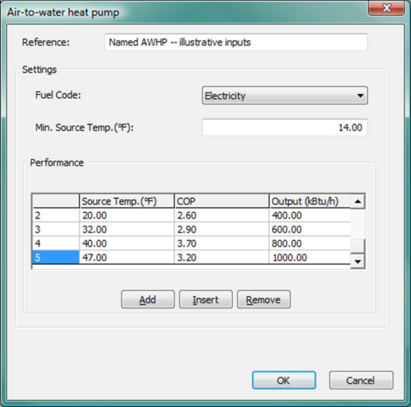
Figure 3 - 28 : AWHP accessed from the Pre-heating tab of the ‘Hot water loop’ dialog.
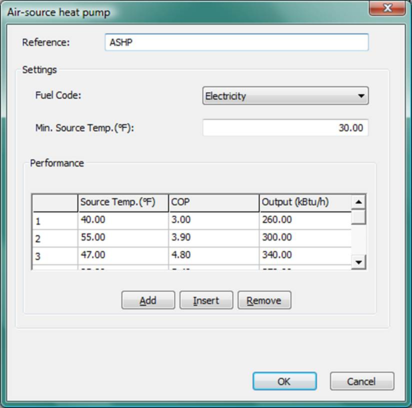
Figure 3 - 29 : ASHP accessed from the ‘Generic heat source’ dialog with illustrative values, including modest capacity and a relatively high minimum source temperature as might be used to model domestic hot water (DHW) heating via heat pump in a warm climate with an otherwise all-electric, cooling-centric space-conditioning system.
Air-to-water and air-source heat pump settings
Reference
Enter a description of the component. The reference is limited to 100 characters. It is for your use when selecting, organizing, and referencing any component or controllers within other component and controller dialogs and in the component browser tree. These references can be valuable in organizing and navigating the system and when the system model is later re-used on another project or passed on to another modeler. Reference names should thus be informative with respect to differentiating similar equipment, components, and controllers.
Fuel Code
Select the fuel, type of energy source, or energy end-use category for the air-to-water or air-source heat pump. For scratch-built systems, this will normally be Electricity and for pre-defined systems this is set to the Heating (electricity) end-use designation for the ASHRAE 90.1 Performance Rating Method reports.
Minimum Source Temperature
The heat pump is assumed to switch off completely when the source temperature drops below this value. Above this value, the heat pump is assumed to meet as much of the load as it can, with the heat source being brought in to top up this demand if required.
Air-to-water and air-source heat pump performance
Source Temperature
This line of information describes the variation in the performance of the heat pump as the source temperature varies. Enter the source temperature. Up to ten points may be used to define the variation of performance with source temperature. Enter the points in ascending order of source temperature.
Heat Pump COP
Enter the coefficient of performance of the heat pump at the corresponding source temperature. This value is the useful heat output divided by the total fuel energy consumption associated with the operation of this device (excluding electrical consumption of any distribution pumps included in heating plant components).
Output
Enter the maximum heat pump output at the corresponding source temperature. If the demand for heat output exceeds this value then the heat source is used to make up the extra demand.
Air-to-air heat pump (AAHP)
The air-to-air heat pump (AAHP) is a new component type to be used in place of an ASHP to represent an air-to-air heat pump serving a simple heating coil.
Data describing AAHPs is organized in an air-to-air heat pump list. Entities on this list are AAHP ‘types’, not instances (in contrast to AWHPs).
A simple heating coil (SHC) can specify an AAHP of a named type as its heat source, as the ‘Air-to-air heat pump’ system type.
The AAHP type data consist of a part-load curve formulated in terms of fractional load (load divided by design load). In other respects its data is similar to that for an old ASHP.
Thus the ‘shape’ of the heat source (fractional part load curve) is an attribute of the AAHP type, and its size (essentially the size of the simple coil) is stored as an attribute of the heating coil. Only the size parameter will need to be updated during system sizing.
Hence, the AAHP instance sizing would be automatically covered by the normal sizing process for its connected simple heating coil. No additional sizing process is needed for the AAHP types.
The AAHP component is accessed through the toolbar button shown below. Clicking this button opens up the Air-to-air heat pump (types) dialog.

Toolbar button for Air-to-air heat pump (types) list
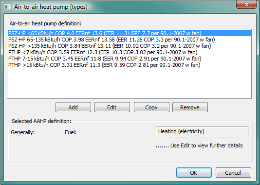
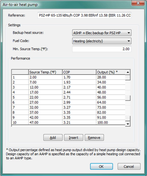
Figure 3 - 30 : Air-to-air heat pump (types) dialog
This facility supports defining the performance characteristics of one or more AAHP types.
The entities defined here are types. A single AAHP type may be assigned to many heating coils. At the time of simulation instance of the AAHP type is automatically created for each heating coil to which the AAHP type is assigned. In this respect AAHP differ from the AWHP attached to a hot water loop (or the ASHP attached to a generic heat source).
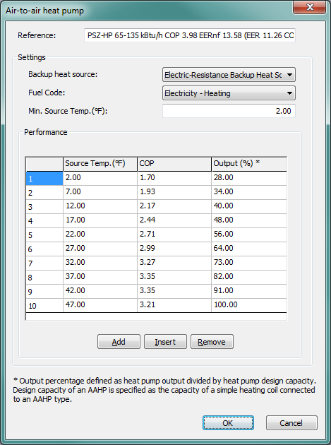
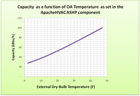
Figure 3 - 31 : Air-to-air heat pump dialog with default inputs as provided for the AAHP in the pre-defined packaged single-zone heat pump (04 PSZ-HP) system when the autosized load range is >135 kBtu/h.
Air-to-air heat pump settings
Reference
Enter a description of the component. The reference is limited to 100 characters. It is for your use when selecting, organizing, and referencing any component or controllers within other component and controller dialogs and in the component browser tree. These references can be valuable in organizing and navigating the system and when the system model is later re-used on another project or passed on to another modeler. Reference names should thus be informative with respect to differentiating similar equipment, components, and controllers.
Backup heat source
Select the backup heat source for the AAHP type. Note that only heat sources of the generic type will be available to be selected as the backup heat source for an AAHP type.
Fuel Code
Select the fuel, type of energy source, or energy end-use category for the air-to-air heat pump. For scratch-built systems, this will normally be Electricity and for pre-defined systems this is set to the Heating (electricity) end-use designation for the ASHRAE 90.1 Performance Rating Method reports.
Minimum Source Temperature
The heat pump is assumed to switch off completely when the source temperature drops below this value. Above this value, the heat pump is assumed to meet as much of the load as it can, with the backup heat source being brought in to meet remaining demand as required.
Typically, the minimum source temperature is the temperature at which the unit will be shut off to optimize overall system operating efficiency or similar. For example, this may be the outdoor temperature at which the heat pump COP would drop to 1.0 when the backup is electric resistance heat. Once the heat pump COP drops to 1.0 or near that value, it may no longer make sense to operate it when the much simpler and therefore less costly to operate electric resistance heating is equally efficient.
Air-to-air heat pump performance
Source Temperature
This line of information describes the variation in the performance of the heat pump as the source temperature varies. Enter the source temperature. Up to ten points may be used to define the variation of performance with source temperature. Enter the points in ascending order of source temperature.
Heat Pump COP
Enter the coefficient of performance of the heat pump at the corresponding source temperature. This value is the useful heat output divided by the total fuel energy consumption associated with the operation of this device (excluding electrical consumption of any distribution pumps included in heating plant components).
Output
Enter the maximum heat pump output at the corresponding source temperature. If the demand for heat output exceeds this value then the backup heat source (if present) is used to make up the extra demand.
Note that AAHP Output is in the form of a percentage value. Output percentage is defined as the heat pump output ( kW in SI units; kBtu/h in IP units ) divided by the heat pump design capacity. Design capacity of an AAHP is specified as the capacity of a simple heating coil connected to an AAHP type.
Modeling heat pump temperature and part-load dependent performance
Figure 3 - 32 : Air-source heat pump dialog with illustrative inputs
The air-source heat pump models (ASHP, AWHP, and AAHP) in ApacheHVAC provide straightforward and very clear means of modeling of the following relationships:
· Air-source-temperature dependent COP
· Air-source-temperature dependent output (heating capacity, not to be confused with load)
· Minimum source temperature for operation
This model does not, however, provide a direct means of accounting for the additional dimension of part-load-dependent COP. The following method of doing so has been used in the pre-defined AAHPs as an illustration of one possible approach to this and can be reproduced by users as appropriate.
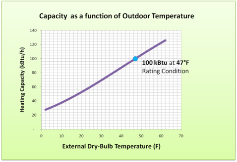
Figure 3 - 33 : Air-source heat pump performance associated with illustrative inputs in Figure 3-32
Figure 3 - 34 : Graphic representation of the illustrative inputs in Figure 3-32
Modeling heat pump temperature and part-load dependent performance
Figure 3-32 ,
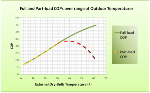
Figure 3-33 , and

Figure 3-34 above show illustrative inputs for the ASHP dialog and the relationship between these and the heat pump capacity curve and full-load COP curve.
To account for both change in performance (output and COP) with outdoor temperature and reduced COP at part load, it is useful to create simple graphs of the first two of these (green and purple lines in Figure 3-33 ) and then use simulation results to determine part-load values corresponding to outdoor temperature above the outdoor temperature at which the heat pump output is well matched to heating load. At lower outdoor temperatures, the heat pump will be fully loaded, and thus the model should use the full-load COP (dashed yellow line segments in Figure 3-33 ). At higher outdoor temperatures, which normally are associated with reduced heating loads, the heat pump COP will tend to decrease with load (dashed orange and red line segments in Figure 3-33 ). If the heat pump is never to be fully loaded at the outdoor temperature associated with the rating condition (e.g., at 47 °F), which is a function of design sizing condition and oversizing, it may be that the COP provided at the rating condition will never be applicable. In other words, because the COP will tend to decrease both with decreasing load (as the outdoor temperature rises above that which corresponds to the fully loaded condition) and with decreasing outdoor temperature below the rating condition, the heat pump COP will always be less than the COP when fully-loaded at the rating condition.
Simulation results were used to determine that the load placed upon the ASHP after sizing would be 100% at 32 °F, with supplemental heat from the backup heat source increasingly required below that temperature and, above 32 °F, heating load gradually diminishing to 40% at an outdoor temperature of 62 °F. This information was used to determine the part-load COP curve (dashed line) in Figure 3-33 . To facilitate insertion of the autosized capacity (based upon the winter heating design day conditions for the project location) in the row associated with the ARI testing condition (47 °F) used to determine the equipment capacity and COP, the curves are intentionally truncated to end at 47 °F.
In the example in Modeling heat pump temperature and part-load dependent performance
Figure 3-32 ,

Figure 3-33 , and
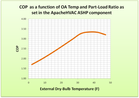
Figure 3-34 above, the COP for the fully loaded heat pump at the 47 °F rating condition would be 4.0, and this is the outdoor temperature at which the full rated capacity would be available. However, when sized to meet the full load at 32 °F, the heat pump load is 81% of full load at 47 °F outdoor temperature for this example. Thus the maximum COP of 3.35 occurs at an outdoor temperature of approximately 37 °F and 95% load and the COP is just 3.2 at 47 °F and 81% load.
The inputs in the ASHP dialog could be extended to warmer temperatures if needed. Because the dialog accepts just 10 rows of data, the spacing between data points would need to be revised to accommodate this. Because the model uses linear interpolation between the data points provided, and the COP and capacity curves are both relatively flat between about 17 and 32 °F for this particular data set, this would be the best region of the curve to be represented by a reduced density of data points.