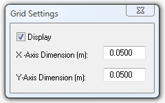
Grid settings
Toolbar button:

; Menu item: “Settings”
Þ “Grid”.
The grid is used as an aid in model creation (provided the appropriate Lock is active). The Grid Settings dialogue box may be left open throughout the drawing process or may be closed and re-opened at any time. You can set the drawing grid spacing in the X and Y directions, determined by the values entered in the X and Y Spacing fields.
Note that if the spacing is too small for the view in the ModelIT window (i.e. if the grid mesh is too fine), the grid will not be displayed. You may display/hide the grid by clicking in the Display box. The Grid and Axis locks will function even if the grid is not displayed.
Grid alignment
Toolbar button:

; Menu item: “Settings”
Þ “Grid alignment”.
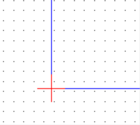
It is always preferable to work orthogonally and in alignment with the grid. This option allows the grid to be aligned with the model.
|
Grid not aligned with model
|
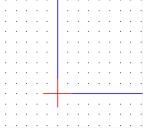
Grid alignment
|
To use this feature switch on the end-point lock and zoom the view in to an area of the model you wish to lock on to. Click the toolbar button and then click once on the vertex point identified we wish to act as anchor. The grid will immediately shift to align with this point.
Used in conjunction with the
Rotate View a user can always obtain an orthogonal grid to align with.
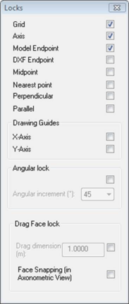
Locks
(“Settings” Þ “Locks”)
Pops-up the following window:
Locks are used to force points placed during drawing operations to fall precisely at positions determined by the lock. The Locks dialogue box may be left open throughout the drawing process or may be closed and re-opened at any time.
Grid
Checking this box causes the origin of a line or other element to be fixed at the nearest grid line intersection (See Endpoint below) to a point on the view determined by a mouse click.
Axis
Checking this box enables a line to be drawn orthogonally with regard to the grid. The position of the mouse pointer with regard to the origin of the line determines which grid line the drawn line follows.
Endpoint
Selecting this option enables you to snap on the nearest end point of an existing line. If the Grid is locked on, the new line/element will snap to the nearest grid unless the Endpoint is nearer.
Midpoint
Selecting this option enables you to snap on the nearest middle point of an existing line. If the Grid is locked on, the new line/element will snap to the nearest grid unless the Midpoint is nearer.
Nearest Point
Selecting this option enables you to snap to a point anywhere along a surface.
Perpendicular
When using draw extruded shape, the line being drawn will display light blue if it is 90 degrees to the previously drawn line.
Parallel
Selecting this option enables you to draw a surface parallel to that of another space. Using the draw extruded shape, move the cursor near the surface which you want to draw parallel to and press shift. Then when you go to draw your surface you will see the line is displayed yellow indicating it is parallel.
Drawing Guides
Selecting this option enables you to draw a line to a snap point in line with another surface either on the X or Y axis. Drawing guides are not designed to be used in conjunction with grid snap.
Angular Lock
Selecting this option enables you to draw a line with draw extruded shape with an angular setting. Find the desired angle and then type in the length of the surface and press <enter>. The surface has then been drawn and you can move on to the next point.
Drag Face Lock
This lock option allows you to control the distance that you adjust a volume size by when you are using the Drag face tool.
Face Snapping
This lock option allows you to drag the face of a space that you are editing to match up with another existing space face without having to type in any dimension information