Drawing spaces
Spaces are created using the facilities Draw extruded shape, Draw prism, Draw pyramid, Draw sphere, Draw hemisphere and Draw cylinder.
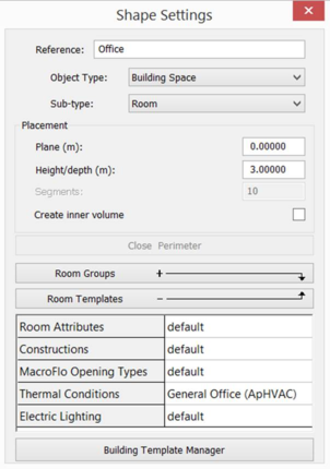
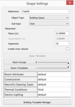
These facilities share a Shape Settings dialog which allows you to specify various attributes of the space.
Reference is the name of the space as it appears on the browser and dialogs.
Object type is the type of space. The options are:
Building Space. A space in the subject building.
Adjacent Building. A space in an adjacent building.
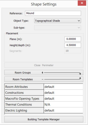
Topographical Shade. A shading object which forms part of the landscape surrounding the building. Adjacent Buildings and Topographical Shades are included in variants of the model created for regulatory compliance and rating analyses.
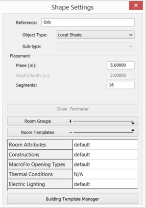
Local Shade. A shading object which forms part of the subject building. Local Shades are not included in variants of the model created for regulatory compliance and rating analyses.
Sub-type is an additional attribute which applies when Object type is Building Space. The options are:
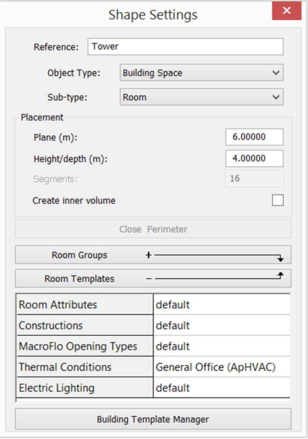
Room. An occupied space, or a space that may at some time be occupied. Rooms assigned the ApHVAC methodology may have plenum associations.
Void. An unoccupied space. Voids do not contribute to building floor area. Like rooms, voids may be assigned internal gains and air exchanges, and may feature in ApacheHVAC systems. Unlike rooms, they may not be conditioned and do not have plenum associations.
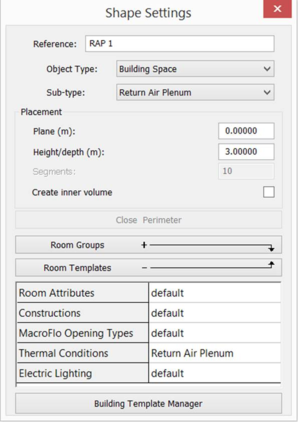
Return Air Plenum. An unoccupied space providing a route for the removal of HVAC system air. Return Air Plenmums (RAPs) are assigned the ApHVAC methodology and are automatically associated with adjacent rooms which are assigned that methodology. These associations may be adjusted by the user. Like rooms, RAPs may be assigned internal gains and air exchanges, and may feature in ApacheHVAC systems. During ASHRAE Loads analyses, a room-associated RAP is held at a temperature offset from the temperature of its primary associated room.
Supply Air Plenum. An unoccupied space providing a route for the supply of HVAC system air. Supply Air Plenmums (SAPs) are assigned the ApHVAC methodology and are automatically associated with adjacent rooms which are assigned that methodology. These associations may be adjusted by the user.Like rooms, SAPs may be assigned internal gains and air exchanges, and may feature in ApacheHVAC systems.
Plane specifies the location of the space in the direction perpendicular to the view. When drawing a sphere this defines the position of the centre of the sphere. In all other cases it defines the position of the base of the object.
Height/depth specifies the height or depth of the object (unless it is a sphere or a hemisphere) in the direction perpendicular to the view.
Segments specifies the number of straight line segments used to approximate a sphere or hemisphere when viewed in plan.
Create inner volume, if ticked, instructs the software to take account of the thickness of the space’s bounding constructions when deriving surface areas and volumes.
Room Groups allows you to specify which space group the new space will belong to in the various space grouping schemes.
Room Templates allows you to specify templates which will be assigned to the new space. In the case of Thermal Conditions, the assignable templates are those whose sub-type match that of the space. (If the sub-type is subsequently changed, a template with a matching sub-type will be assigned automatically). The Thermal Conditions template assigned to a room specifies (inter alia) the room’s HVAC methodology.
Draw extruded shape
(“Draw” Þ “Extruded Shape”)
Displays the following dialog:
This facility creates an extruded shape as a series of straight-line segments. Select each point of the shape in turn, in either clockwise or anti-clockwise order. To close the shape, click on the “Close Shape” button which is active while you are drawing the shape. If you make a mistake and need to undo a point, click on the right mouse button. The current lock settings will apply and key-in values can also be used. The extruded shape will be created with the defined Plane (m) and Depth (m) values as currently set in the Shape Settings dialogue box. An extruded shape can be created along any axis.
Note that you cannot cross a segment with another segment and you cannot place a perimeter point on an existing perimeter point unless it is the first point in which case this will close the shape.
The relevant key-ins for the extruded shape are:
x=<x, y>
dx=<dx, dy>
p=<length, angle>.
Draw prism
(“Draw” Þ “Prism”)
Displays the following dialog:
This facility creates a rectangular-based prism. Select the point where one corner of the prism is to be located, then select the point that is at the opposite corner of the prism. A prism will then be created with the defined Plane (m) and Depth (m) values as currently set in the Shape Settings dialogue box. A prism can be created along any axis.
The relevant key-ins for the prism are:
x=<x, y>
dx=<dx, dy>
p=<length, angle>.
Draw pyramid
(“Draw” Þ “Pyramid”)
Pyramids are created in a very similar way to extruded shapes except that after completing the perimeter, you will enter a point to define the apex of the pyramid.
Displays the following dialog:
This facility creates a pyramid. First define the shape of the base of the pyramid and then position the apex. To define the pyramid base, select each point on the perimeter of the base in turn, in either clockwise or anti-clockwise order. To close the shape, click on the "Close Shape" button on the Shape Settings dialogue box which is active while you are drawing the shape. Next, select the position of the apex. A new pyramid will be created with the base at the defined Plane (m) value as currently set, and the apex at the Plane + Depth (m) values as currently set. A pyramid can be created along any axis.
The relevant key-ins for the pyramid are:
x=<x, y>
dx=<dx, dy>
p=<length, angle>.
Draw sphere
(“Draw” Þ “Sphere”)
Displays the following dialog:
This facility creates a sphere. First select the centre of the sphere and then select a point which defines the radius of the sphere. A new sphere will be created with its centre at the defined Plane (m) level that is currently set in the Shape Settings dialogue box which is active while you are drawing the shape. The number of chord segments which make up the sphere is defined in the Shape Settings dialogue box. A sphere can be created along any axis.
The relevant key-ins for the sphere are:
x=<x, y>
dx=<dx, dy>
p=<length, angle>.
Draw hemisphere
(“Draw” Þ “Hemisphere”)
Hemispheres are created in exactly the same way as spheres.
Displays the following dialog:
This facility creates a hemisphere. First select the centre of the hemisphere and then select a point which defines the radius of the hemisphere. A new hemisphere will be created with its base at the defined Plane (m) level that is currently set in the Shape Settings dialogue box which is active while you are drawing the shape. The number of chord segments which make up the hemisphere is defined in the Shape Settings dialogue box. A hemisphere can be created along any axis.
The relevant key-ins for the hemisphere are:
x=<x, y>
dx=<dx, dy>
p=<length, angle>.
Draw cylinder
(“Draw” Þ “Cylinder”)
Cylinders are created in a similar way to spheres and hemispheres.
Displays the following dialog:
This facility creates a cylinder. First select the centre of the cylinder and then select a point that defines the radius of the cylinder. A new object will be created with the defined Plane (m) and Height/Depth (m) at the values currently set in the Shape Settings dialogue box which is active while you are drawing the shape. The number of chord segments which make up the cylinder is defined in the Shape Settings dialogue box. A cylinder can be created along any axis.
The relevant key-ins for the cylinder are:
x=<x, y>
dx=<dx, dy>
p=<length, angle>.
Draw arc
(“Draw” Þ “Arc”)
If you want to incorporate an arc within the perimeter of an extruded shape or pyramid base, use this option. This button becomes active after you have placed the first point of an extruded shape or pyramid perimeter. It allows you to define a curve that originates from the last vertex you have placed. The “Arc Settings” dialogue box opens -
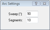
The "Sweep" setting is used to define the sweep angle (in degrees) of the arc, a positive value for a clockwise sweep and negative for an anti-clockwise sweep. The "Segments" setting is used to define the number of straight-line segments used to create the arc. The accuracy of the arc may be improved by increasing the number of segments. However, the greater the number of segments, the longer the processing times will be. When you move the cursor back into the model window, you will see a small circle attached to the cursor. This circle is used to define the centre of the arc. When the arc is placed, you may place another arc, or press the right mouse button to continue drawing the extruded shape or ‘unwind’ the arc segment by segment by repeatedly pressing the right mouse button.