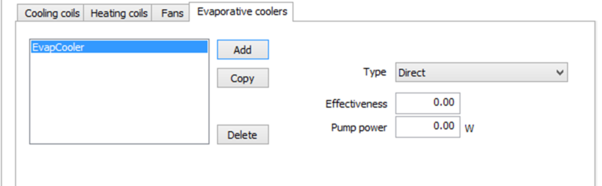
Evaporative Cooling (Direct)
Figure 88 - Evaporative Cooling (Direct) Input Dialog
Input Summary:
· Type: The type of evaporative cooler. For Indirect or Direct evaporative coolers, specify the indirect and direct portions as two separate devices.
· Effectiveness: The effectiveness of the evaporative cooler. The leaving air temperature will be the entering temperature minus the difference between the entering dry-bulb and wet-bulb temperatures multiplied by the effectiveness, Tout = Tdb - (Tdb - Twb) x Eff.
· Pump Power (Watts): Power consumption by the evaporative cooler water pumping.
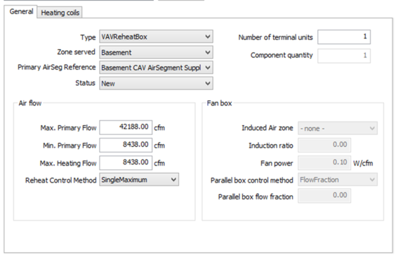
Terminal Units
Figure 89 - Terminal Unit Data Input Dialog
Input summary:
· Type : The type of terminal used to deliver and if applicable, regulate air delivery to a thermal zone
· Zone Served : The name of the HVAC zone that the terminal unit provides air to
· Primary AirSeg Reference : Definition of the supply air segment that provides primary air to the terminal unit
· Status : Options are New and Existing
· Number of Terminal Units: The number of duplicate terminal units represented by the current terminal unit
· Component quantity: The number of duplicate systems represented by the current system. The number of duplicate systems can only be >1 when all attributes of the system are the same. If Count is specified to be >1, all parameters (capacities, power, etc.) should be specified for the single piece of equipment. The ruleset applies multipliers for the final simulation.
Air Flow section (For single system/terminal if Component Qty > 1)
· Max. Primary Flow : The zone air delivery rate at design conditions. For uncontrolled terminal units, describes the design air flow rate provided to zones when the system is on. For VAV systems, specifies the maximum air flow delivered to the zone by the terminal unit.
· Min. Primary Flow : The minimum air flow rate of variable volume terminal units
· Max. Heating Flow : The maximum primary air flow to the terminal in heating mode
· Reheat Control Method : The air/temperature control strategy for VAV reheat box in heating mode. Options available are Single Maximum and Dual Maximum.
o Single Maximum: The airflow is set to a minimum constant value in both the deadband and heating mode. The minimum airflow setpoint is typically 30 to 50 percent of maximum. This control mode typically has a higher minimum airflow than the minimum used in the dual maximum below, resulting in more frequent reheat.
o Dual Maximum: Raises the SAT as the first stage of heating, and increases the airflow to the zone as the second stage of heating, as follows:
§ The first stage of heating consists of modulating the zone supply air temperature setpoint up to a maximum setpoint no larger than 95°F while the airflow is maintained at the deadband flow rate.
§ The second stage of heating consists of modulating the airflow rate from the deadband flow rate up to the heating maximum flow rate (50 percent of design flow rate)
Fan box section:
· Induced Air Zone: Specifies the zone from which secondary air is drawn by a fan-powered box.
· Induction Ratio: The ration of induced secondary airflow to the total design airflow of a fan-powered box.
· Fan Power: Specifies the power consumption at full load of the fan in a fan-powered box.
· Parallel Box Control Method: Control method for parallel powered fan boxes.
· Parallel Box Flow Fraction: The fraction of the primary air flow at which fan turns on. In the parallel PIU the fan operation is intermittent. If the primary air flow is above this fraction of the maximum, the fan is off.
For heating coils see the sections 4.11.2.3.3 - 4.11.2.3.6.
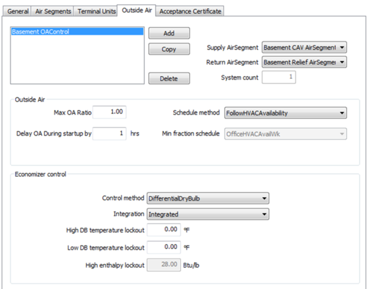
Outside Air
Figure 90 – Outside Air Control Input Dialog
Input summary:
· Supply AirSegment : Defines the supply air segment of the Air System
· Return AirSegment : Defines the return/relief air segment of the Air System
· System count : The number of duplicate systems represented by the current system. The number of duplicate systems can only be >1 when all attributes of the system are the same. If Count is specified to be >1, all parameters (capacities, power, etc.) should be specified for the single piece of equipment. The ruleset applies multipliers for the final simulation
Outside Air section (For single system/terminal if Component Qty > 1)
· Max OA Flow (For individual systems, not total if # of systems>1): The maximum ratio of outside air that a system can provided, defined as a percentage of the design supply air. Applies to systems with modulating outside air dampers. Economizers for smaller systems (<54,000 Btu/h) are assumed to have a restricted intake capacity
· Delay OA During Startup By : If the OAScheduleMethod is 'FollowHVACAvailability', this positive integer value indicates the number of hours that the system outside air flow is zero during system start up
· Schedule Method : The method used to describe the minimum amount of ventilation (outdoor) air that is provided by the system
· Min Fraction schedule : A schedule that defines the minimum outdoor air flow rate as a fraction of total system airflow
Economizer Controls section
· Control method : The method used to control the air-side economizer. An air-side economizer increases outside air ventilation during periods when mechanical cooling loads can be reduced by increasing outside airflow. The control types include:
o No economizer: Fixed outside are fraction at the system's design outside air flow when the system fan runs
o Fixed dry-bulb: The system shifts to 100 percent outside air and shuts off the cooling when the temperature of the outside air is equal to or lower than the supply air temperature
o Differential dry-bulb: The system shifts to 100 percent outside air when the temperature of the outside air is lower than the return air temperature but continues to operate the cooling system until outside air temperature reaches the supply air temperature
o Differential enthalpy: The system shifts to 100 percent outside air when the enthalpy of the outside air is lower than the return air enthalpy but continues to operate the cooling system until the outside air enthalpy reaches the supply air enthalpy
o Differential enthalpy and dry-bulb: Utilizes combination of both the DifferentialDryBulb and DifferentialEnthalpy economizer control strategies
· Integration : Specifies whether or not the economizer is integrated with mechanical cooling. Options include:
o NonIntegrated: The system runs the economizer as the first stage of cooling. When the economizer is unable to meet the load, the economizer returns the outside air damper to the minimum position and the compressor turns on as the second stage of cooling
o Integrated: The system can operate with the economizer fully open to outside air and mechanical cooling active (compressor running) simultaneously, even on the lowest cooling stage
· High DB Temperature Lockout : The outside air drybulb temperature above which the economizer will return to its minimum position
· Low DB Temperature Lockout : The outside air drybulb temperature below which the economizer will return to its minimum position
· High Enthalpy Lockout : The outside air drybulb temperature above which the economizer will return to its minimum position
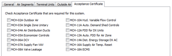
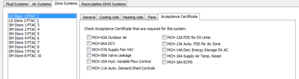
Acceptance Certificates
Figure 91 – Acceptance Certificates
Input Summary:
· Acceptance Certificates: Check Acceptance Certificates indicating whether an acceptance certificate of the number matching the term name is required (used for reporting).
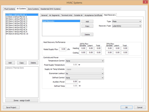
Heat Recovery
Figure 92 – Air Systems Heat Recovery Tab
Input Summary:
· Type: Type of Heat Recovery object. Options are plate and wheel.
· Recovery Type: Select from options Total, Sensible Only and Latent Only.
Heat Recovery Performance section:
· Rated Supply Flow : The 100% supply air flow rate at which the heat recovery object is rated.
· 100% Flow- Heating (Sensible) :The sensible heat exchange effectiveness at heating condition with both supply and exhaust air volume flow rates equal to 100%
· 100% Flow- Heating (Latent) : The latent heat exchange effectiveness at heating condition with both supply and exhaust air volume flow rates equal to 100%
· 100% Flow- Heating (Total ): The total heat exchange effectiveness at heating condition with both supply and exhaust air volume flow rates equal to 100%
· 100% Flow- Cooling (Sensible) : The sensible heat exchange effectiveness at cooling condition with both supply and exhaust air volume flow rates equal to 100%
· 100% Flow- Cooling (Latent) : The latent heat exchange effectiveness at cooling condition with both supply and exhaust air volume flow rates equal to 100%
· 100% Flow- Cooling (Total) : The total heat exchange effectiveness at cooling condition with both supply and exhaust air volume flow rates equal to 100%
· 75% Flow- Heating (Sensible) : The sensible heat exchange effectiveness at heating condition with both supply and exhaust air volume flow rates equal to 75%
· 75% Flow- Heating (Latent) : The latent heat exchange effectiveness at heating condition with both supply and exhaust air volume flow rates equal to 75%
· 75% Flow- Heating (Total) : The total heat exchange effectiveness at heating condition with both supply and exhaust air volume flow rates equal to 75%
· 75% Flow- Cooling (Sensible) : The sensible heat exchange effectiveness at cooling condition with both supply and exhaust air volume flow rates equal to 75%
· 75% Flow- Cooling (Latent): The latent heat exchange effectiveness at cooling condition with both supply and exhaust air volume flow rates equal to 75%
· 75% Flow- Cooling (Total): The total heat exchange effectiveness at cooling condition with both supply and exhaust air volume flow rates equal to 75%
Controls and Power section:
· Temperature Control: Indicates if the heat recovery objects supply air outlet is controlled by a temperature setpoint.
· Fixed Supply Temp. : Fixed supply temperature at the heat exchangers supply outlet.
· Supply Air Temp Sch : The supply air temperature schedule of the temperature setpoint at supply outlet.
· Economizer Lockout : This field indicates whether the heat exchanger is locked out when the economizer is operating.
· Auxiliary Power : The electric consumption rate of the heat recovery object.
· Defrost Control : The defrost control method of the heat exchanger.
· Defrost Temp. : The defrost temperature of the heat exchanger object.
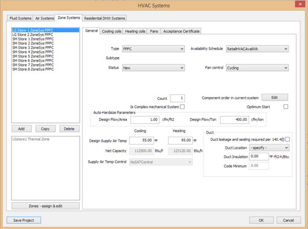
Zone Systems
Figure 93 – Zone System Input Dialog
Input Summary:
· Type: Select the type of zone system. Options are PTAC, PTHP, FPFC, Baseboard, WSHP, Exhaust, SPVAC, SPVHP.
· Availability Schedule: The schedule that defines when the zone system can operate.
· Status: Defines system status as New, Existing, or Altered.
· Sub Type: Property used to define rating conditions and efficiency requirements of system
· components. Options available are Packaged 3Phase, Split3Phase, Packaged1Phase, and
· Split1Phase.
· Fan Control: The zone HVAC system fan control method system is scheduled to be On.
· Count: The number of duplicate systems represented by the current system. The number of duplicate systems can only be >1 when all attributes of the system are the same. If Count is specified to be >1, all parameters (capacities, power, etc.) should be specified for the single piece of equipment. The ruleset applies multipliers for the final simulation.
· Complex Mechanical System? (per Section 10-102): Check to indicate whether an HVAC system is Simple or Complex, used for reporting. Complex systems serve multiple zones or use hydronic heating or cooling. Simple systems are all other systems. PTAC, PTHP and exhaust zone systems are simple – FPFC,WSHP and Baseboard zone systems are complex.
· Design Supply Air Temp (Cooling): The design cooling supply air temperature for sizing zone/system airflows.
· Design Supply Air Temp (Heating): The design heating supply air temperature for sizing zone/system airflows.
· Net Capacity (Cooling): The net cooling capacity of the ZoneSystem.
· Net Capacity (Heating): The net heating capacity of the ZoneSystem.
· Supply Temp Control: The method of controlling the supply air temperature of a single duct system, or the cold duct of dual duct system.
· Design OA Flow: The rate of outside air that needs to be delivered by the system at design conditions.
Duct (Input summary):
Note: These inputs are for reporting only and will not impact simulation results.
· Duct Insulation : The duct insulation R-value for reporting
· Duct Location : The duct location (Conditioned, Unconditioned, NA) for reporting
· Duct Leakage and sealing required per 140.4(l) (check box): Check box to indicate whether HERS duct leakage testing is required, used for reporting. HERS duct leakage testing is required if duct systems: 1. Supply conditioned air to occupiable space from a single zone constant speed system, 2. Serve less the 5,000 ft2 of conditioned floor area, and 3. More than 25% of the total duct system surface area is located in unconditioned space.
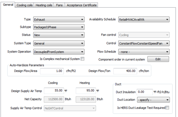
Zone System (Exhaust)
Figure 94 – Zone System Exhaust Input Dialog
Input Summary:
· Type: The type of exhaust system. This input is used to default assumptions for system controls and power. Options available are Laboratory, Commercial Kitchen and Parking Garage exhaust systems and can only be assigned to thermal zones comprised of the applicable SpaceFunction categories.
· Sub Type: Property used to define rating conditions and efficiency requirements of system components. Options available are Packaged 3Phase, Split3Phase, Packaged1Phase, and Split1Phase.
· Status: Defines system status as New, Existing, or Altered.
· System Type: The type of exhaust system. This input is used to default assumptions for system controls and power. Options available are Laboratory, Commercial Kitchen and Parking Garage exhaust systems and can only be assigned to thermal zones comprised of the applicable SpaceFunction categories.
· System Operation: Describes whether exhaust system availability control is interlocked with the HVAC system availability. For compliance analysis, exhaust fans are assumed to have the same availability schedule as the ThermalZone's ventilation system, but does not night cycle. Options available are DecoupledFromSystem and CoupledFromSystem.
· Availability Schedule: Select the name of the Availability schedule for the Air System.
· Control: Control Type for the Exhaust System. Options available are ConstantFlowConstantSpeedFAn, VariableFlowConstantSpeedFan, VariableFlowVariable SpeedFan.
· Flow Schedule: The schedule that defines the flow schedule for the system. This schedule is prescribed for Type = Commercial Kitchen and Laboratory exhaust systems. For General exhaust, the schedule is user defined, but will default to match the HVAC system availability schedule for the ThermalZones that the exhaust system serves. For Parking Garage systems, the schedule is prescribed to be constant, and the fan power is adjusted to account for variable speed fan control.
· Complex Mechanical System? (Per Section 10-102): Check to indicate whether HVAC system is simple or complex (for reporting purposes).
Cooling Coils
See Sections 4.11.2.3.1 and 4.11.2.3.2.
Heating Coils
See Sections 4.11.2.3.3, 4.11.2.3.4, 4.11.2.3.5, 4.11.2.3.6.
Fans
See Section 4.11.2.3.7
Acceptance Certificates
Figure 95 – Acceptance Certificates
Input Summary:
· Acceptance Certificates: Check boxes to indicate whether an acceptance certificate of the number matching the term name is required, used for reporting.
Residential DHW Systems
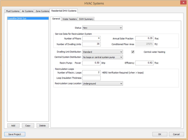
General
Figure 96 – Recirculation DHW System General Tab
Input summary:
· Status: The status of the system or component used for additions and alterations. Options are New, Existing, and Altered.
· Number of Floors: Indicates number of floors served by the residential water heating system.
· Number of Dwelling Units: Indicates number of dwelling units served by the residential water heating system.
· Annual Solar Fraction: Annual solar fraction of the fluid system.
· Conditioned Floor Area: Conditioned floor area served by the system.
· Dwelling Unit Distribution: The type of ResidentialWater heating system. Options are Standard,Pipe Insulation All Lines,Parallel Piping, Recirculation options and Water heating system with HERS requirements.
· Central water heating (checkbox): Indicates whether the active ResidentialWater Heating system is part of a central water heating system.
· Central System Distribution: Indicates type of recirculation loop from available options of Demand Control, No loops, No Control or Temperature Modulation options. Available only when Central water heating checkbox is checked.
· Recirc Pump Power: Recirculation pump brake horsepower. Available only when Central water heating checkbox is checked.
· Recirc Pump Efficiency: Efficiency of the Recirculation Pump. Available only when Central water heating checkbox is checked. Recirculation Loops section (Available only when Central water heating checkbox is checked).
· Number of Recirculation Loops: The number of identical recirculation loops.
· Loop Insulation Thickness: The Thickness of the loop insulation.
· Recirculation Loop Location: The Location of the recirculation loop. Options are Conditioned, Semi-Conditioned, Unconditioned or Underground.
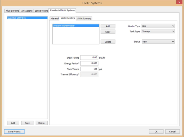
Water Heaters
Figure 97 – Recirculation DHW System Water Heaters Tab
Input Summary:
Fuel Source: The water heater fuel source. Options are Electric Resistance, NaturalGas and Propane, Heat Pump and Oil.
Tank Category: The category of the Recirculation Water Heater Tank. Options are Boiler, Indirect, Instantaneous and Storage.
Tank Location: The surrounding location of the Recirculation Water Heater Tank. Options are Conditioned and Unconditioned.
Status: Defines system status as New, Existing, or Altered.
Capacity Rated (Btu/hr): The heating capacity of a water heater at the rated conditions specified in DOE 10 CFR Part 430 or ANSI z21.10.
Thermal Efficiency: Thermal efficiency of the Recirculation Water Heater.
Energy Factor: The energy factor (EF) is the ratio of the energy delivered by the water heater divided by the energy used in the same units.
Tank Volume:The Recirculation Water Heater Tank volume in gal.
Standby Loss Frac: The Recirculation Water Heat.
Exterior Ins. R-value: The Recirculation Water Heater exterior insulation in 0Fft2h/Btu.
Interior Ins. R-value: The Recirculation Water Heater interior insulation in 0Fft2h/Btu.
Solar Hot Water (SHW) Summary
See section 4.11.1.9.
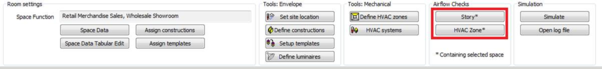
Airflow Checks
Airflow Checks screen can be accessed using the “Story” or “HVAC Zone” buttons when a zone is selected.
Figure 98 – Airflow checks
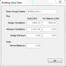
Story
Figure 99 – Building Story Data Screen
Input Summary:
· Room Group’s Name : The name of the currently selected building story.
Ventilation/Exhaust Flows section
· Design Ventilation Flow (Total [cfm]) : The quantity of ventilation air flow (per the proposed design) that is provided to the Building Story at design occupancy.
· Design Ventilation Flow (For Balance [cfm]) : The quantity of ventilation air flow (per the proposed design) that is provided to the Building Story and included in the ventilation air flow balance.
· Minimum Ventilation Flow (Total [cfm]) : The quantity of ventilation air flow (required per NACM rules) that is provided for the Building Story at design occupancy.
· Minimum Ventilation Flow (For Balance [cfm]) : The quantity of ventilation air flow (required per NACM rules) that is provided for the Building Story and included in the ventilation air flow balance.
· Design Exhaust Flow (Total [cfm]) : The design exhaust air flow for the Building Story.
· Design Exhaust Flow (For Balance [cfm]) : The design exhaust air flow for the Building Story included in the ventilation air flow balance.
· MinVentBalanceRatio : The ratio of design ventilation air to the NACM required ventilation air for the Building Story.
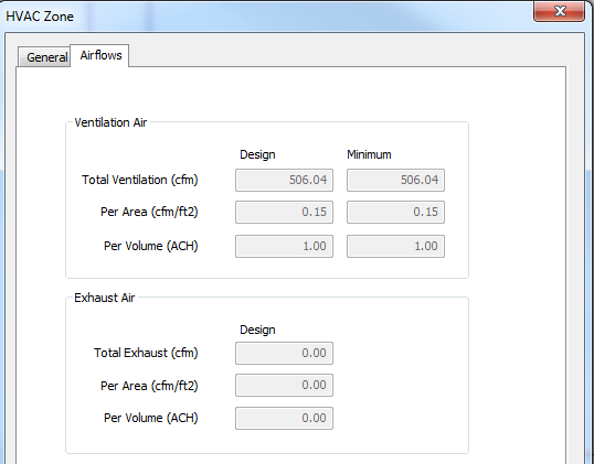
HVAC Zone
For the General tab see section 4.11.
Figure 100 – HVAC Zone Airflows
Input Summary:
Ventilation Air Section
· Total Ventilation (cfm) (Design) : The quantity of ventilation air, per the proposed design, that is provided to the Story at design occupancy. The default value shall be the larger of 15 cfm times the design occupancy from Appendix 5.4A or the conditioned floor area times the applicable ventilation rate from Appendix 5.4A or Table 120.1-A of the Standards.
· Total Ventilation (cfm) (Minimum) : The minimum quantity of ventilation air, per the NACM, that must be provided to the HVAC Zone at design occupancy. The default value shall be the larger of 15 cfm times the design occupancy from Appendix 5.4A or the conditioned floor area times the applicable ventilation rate from Appendix 5.4A or Table 120.1-A of the Standards.
· Per Area (cfm/ft2) (Design) : The design ventilation air flow rate, in cfm/ft2, for the HVAC Zone.
· Per Area (cfm/ft2) (Minimum) : The minimum ventilation air flow rate, in cfm/ft2, for the ThermalZone.
· Per Volume (ACH) (Design) : The design air flow rate, in ACH, for the HVAC Zone.
· Per Volume(ACH) (Minimum) : The minimum air flow rate, in ACH, for the HVAC Zone.
Exhaust Air section
· Total Exhaust (cfm) : The design exhaust air flow rate in cfm for the thermal zone.
· Per Area (cfm/ft2) : The design exhaust air flow rate in cfm/ft2 for the thermal zone.
· Per Volume (ACH) : The design exhaust air flow rate in ACH for the thermal zone.