Electric Air-cooled Chillers
The electric air-cooled chiller model simulates the performance of an electric chiller cooled by outdoor air. The model uses default or user-defined chiller performance characteristics at rated conditions along with three performance curves for cooling capacity and efficiency to determine chiller performance at off- rated conditions.
The three chiller performance curves used are:
· Chiller cooling capacity (temperature dependence) curve
· Chiller electric input ratio (EIR) (temp dependence) curve
· Chiller electric input ratio (EIR) (part-load (and temperature) dependence) curve
Energy consumption by condenser fans is included in the chiller’s Electric Input Ratio (EIR) and associated performance curves. A condenser fan Electric Input Ratio (EIRfan), representing the ratio of condenser fan power consumption to the total chiller power consumption, is used to split the energy consumption calculated by the performance curves into the condenser fan power consumption and chiller compressor energy consumption.
Air-cooled chiller definition
Reference
Enter a description of the component. Reference names should be informative with respect to differentiating similar equipment. It is for your use when selecting, organizing, and referencing any equipment within other component and controller dialogs and in the component browser tree. These references can be valuable in organizing and navigating the system and when the system model is later re-used on another project or passed on to another modeler.
Fuel
Select the “fuel” or energy source used by the chiller compressor to determine the category for reporting energy consumption results. For scratch-built system models, this should normally be set to “Electricity” for the electric chillers. It will be pre-set to “Cooling” as an energy end-use category (consistent with LEED EA credit 1 submittal requirements) when working with the pre-defined prototype ApacheHVAC systems, as provided by the Prototype Systems Library, System Prototypes & Sizing facility, or the ASHRAE 90.1 PRM workflow navigator.
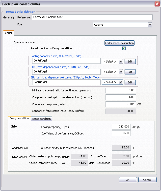 Figure 3 - 110 :
 Electric air-cooled chiller dialog
Chiller Performance
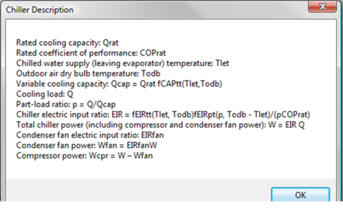
Chiller Model Description
Clicking this button provides a summary of the electric water-cooled chiller model variables as shown below:
Figure 3 - 111 : Electric air-cooled chiller model description
Rated Condition is Design Condition
When this box is ticked, the rated condition data (see details in the Rated condition sub-tab) is a read-only copy of the current design condition data (see details in the Design condition sub-tab), including any unsaved edits you have made.
Cooling Capacity Curve, fCAPtt(Tlet,Todb)
This field indicates the currently selected performance curve for chiller capacity as a function of leaving evaporator water temperature and outdoor air dry-bulb temperature for a particular chiller equipment type. Use the Select button to choose the appropriate curve from the system database.
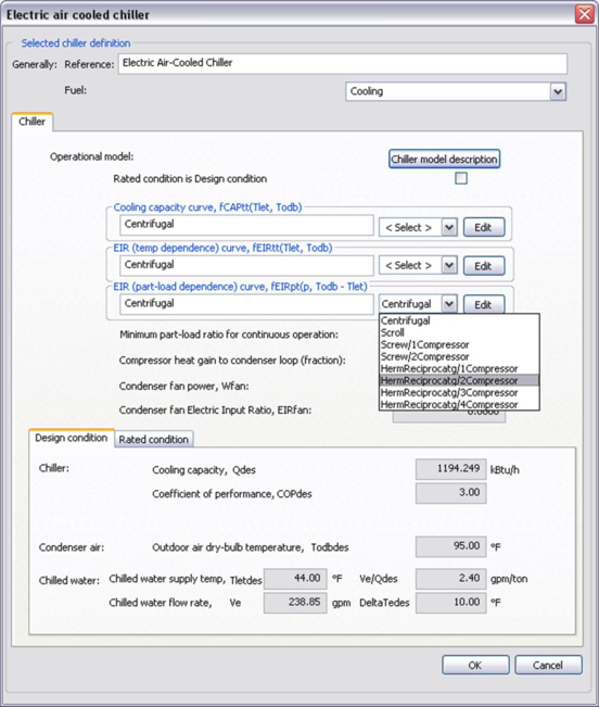 Figure 3 - 112 :
 Electric air-cooled chiller dialog showing drop-down selection for cooling capacity curve.
Edit Cooling Capacity Curve, fCAPtt(Tlet,Todb)
The Edit button opens a dialog displaying the formula and parameters of the curve, allowing the curve parameters to be edited, if needed. However, this is recommended for advanced users only and requires both sufficient data from a manufacturer and an appropriate tool, such as MatLab, for generating the proper fit curve coefficients. For most users, selecting a representative curve for the chiller type and then entering appropriate performance characteristics (COP, cooling capacity, supply temperature, etc.) in the rated and design conditions tabs will be most appropriate.
When editing the curve parameters, it is important that you understand the meaning of the curve and its usage in the model algorithm. The edited curve should have reasonable ranges for the independent variables, as a given performance curve is only valid within its applicable ranges. If the independent variables are out of the set applicable ranges, the variable limits (maximum or minimum) specified in the input dialog will be applied.
Figure 3 - 113 : Edit dialog for the cooling capacity curve of electric air-cooled chiller
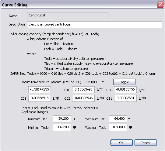
The cooling capacity curve f CAPtt (T let, T odb ) is a bi-quadratic function of
tlet = Tlet – Tdatum
todb = Todb – Tdatum
where
T odb = outdoor air dry bulb temperature.
T let = chilled water supply (leaving evaporator) temperature.
T datum = datum temperature (0°C or 0°F), introduced for the convenience of units conversion of the curve coefficients.
And:
fCAPtt(Tlet, Todb) = (C00 + C10 tlet + C20 tlet 2 + C01 todb + C02 todb 2 + C11 tlet todb) / Cnorm
where
C 00 , C 10 , C 20 , C 01 , C 02 and C 11 are the curve coefficients
C norm is adjusted (by the program) to make f CAPtt (T letrat, T odbrat ) = 1
T odbrat = rated outdoor air dry bulb temperature.
T letrat = rated chilled water supply (leaving evaporator) temperature.
The cooling capacity curve is evaluated at each iteration of the chiller performance, for each time step during the simulation. The curve value is multiplied by the rated cooling capacity (Q rat ) to get the available (full-load) cooling capacity (Q cap ) of the current time step, for the specific T odb and T let temperatures:
Qcap = Qrat fCAPtt(Tlet,Todb)
The curve should have a value of 1.0 when the temperatures are at rated conditions.
EIR (Temp Dependence) Curve, fEIRtt(Tlet,Todb)
This field indicates the currently selected performance curve for chiller Electric Input Ratio (EIR) as a function of leaving evaporator temperature and outdoor dry-bulb temperature (for condenser heat rejection) for a particular chiller type. Use the Select button to choose the appropriate curve from the system database.
Edit EIR (Temp Dependence) Curve, fEIRtt(Tlet,Todb)
The Edit button opens a dialog displaying the formula and parameters of the curve, allowing the curve parameters to be edited, if needed. However, this is recommended for advanced users only and requires both sufficient data from a manufacturer and an appropriate tool, such as MatLab, for generating the proper fit curve coefficients. For most users, selecting a representative curve for the chiller type and then entering appropriate performance characteristics (COP, cooling capacity, supply temperature, etc.) in the rated and design conditions tabs will be most appropriate.
When editing the curve parameters, it is important that you understand the meaning of the curve and its usage in the model algorithm. The edited curve should have reasonable ranges for the independent variables, as a given performance curve is only valid within its applicable ranges. If the independent variables are out of the set applicable ranges, the variable limits (maximum or minimum) specified in the input dialog will be applied.
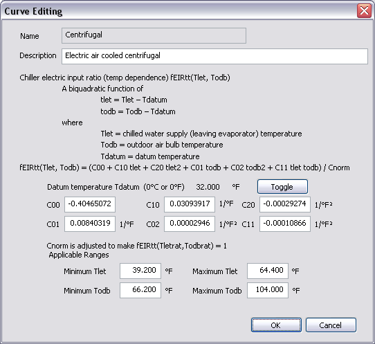 Figure 3 - 114 :
 Edit dialog for the EIR (temperature dependence) curve of electric air cooled chiller
The chiller EIR (temperature dependence) curve f EIRtt (T let, T odb ) is a bi-quadratic function of
tlet = Tlet – Tdatum
todb = Todb – Tdatum
where
T odb = outdoor air dry bulb temperature.
T let = chilled water supply (leaving evaporator) temperature.
T datum = datum temperature (0°C or 0°F), introduced for the convenience of units conversion of the curve coefficients.
And:
fEIRtt(Tlet, Todb) = (C00 + C10 tlet + C20 tlet 2 + C01 todb + C02 todb 2 + C11 tlet todb) / Cnorm
where
C 00 , C 10 , C 20 , C 01 , C 02 and C 11 are the curve coefficients
C norm is adjusted (by the program) to make f EIRtt (T letrat, T odbrat ) = 1
T odbrat = rated outdoor air dry bulb temperature.
T letrat = rated chilled water supply (leaving evaporator) temperature.
The chiller EIR (temperature dependence) curve is evaluated for each iteration of the chiller performance, for each time step during the simulation. The curve value is multiplied by the rated EIR (= 1/ COP rat , where COP rat is the rated coefficient of performance) to get the full-load EIR of the current time step, for the specific T odb and T let temperatures. The curve should have a value of 1.0 when the temperatures are at rated conditions.
EIR (Part-load Dependence) curve, fEIRpt(p,Todb–Tlet)
This field indicates the chiller Electric Input Ratio (EIR) part-load dependence curve currently selected. This is the performance curve for chiller Electric Input Ratio (EIR) as a function of part-load fraction, outdoor dry-bulb air temperature, and supply (leaving evaporator) water temperature for a particular chiller type. Use the Select button to choose the appropriate curve from the database.
Edit EIR (Part-load and temperature dependence) curve, fEIRpt(p,Todb–Tlet)
The Edit button opens a dialog displaying the formula and parameters of the curve, allowing the curve parameters to be edited, if needed. However, this is recommended for advanced users only and requires both sufficient data from a manufacturer and an appropriate tool, such as MatLab, for generating the proper fit curve coefficients. For most users, selecting a representative curve for the chiller type and then entering appropriate performance characteristics (COP, cooling capacity, supply temperature, etc.) in the rated and design conditions tabs will be most appropriate.
When editing the curve parameters, it is important that you understand the meaning of the curve and its usage in the model algorithm. The edited curve should have reasonable ranges for the independent variables, as a given performance curve is only valid within its applicable ranges. If the independent variables are out of the set applicable ranges, the variable limits (maximum or minimum) specified in the input dialog will be applied.
The chiller EIR (part-load and temperature dependence) curve f EIRpt (p,t) is a bi-quadratic function of
p = Q/Q cap
t = T odb –T let
where
p = part-load fraction
Q = cooling load
Q cap = available (full-load) cooling capacity
T odb = outdoor air dry bulb temperature.
T let = chilled water supply (leaving evaporator) temperature.
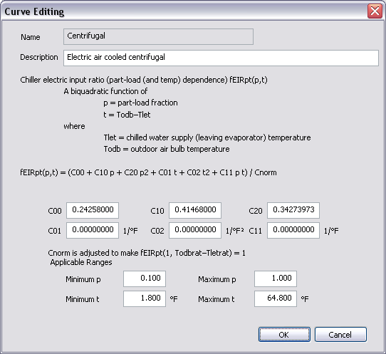 Figure 3 - 115 :
 Edit dialog for the EIR (part-load and temperature dependence) curve of electric air-cooled chiller
And:
f EIRpt (p,t) = (C 00 + C 10 p + C 20 p 2 + C 01 t + C 02 t 2 + C 11 p t) / C norm
where
C 00 , C 10 , C 20 , C 01 , C 02 and C 11 are the curve coefficients,
C norm is adjusted (by the program) to make f EIRpt (1 , T odbrat –T letrat ) = 1
T odbrat = rated outdoor air dry bulb temperature.
T letrat = rated chilled water supply (leaving evaporator) temperature.
The chiller EIR (part-load and temperature dependence) curve is evaluated in each iteration of the chiller performance, for each time step during the simulation. The curve value is multiplied by the rated EIR (= 1/ COP rat , where COP rat is the rated coefficient of performance) and the EIR (temperature dependence) curve value to get the EIR of the current time step, for the specific T odb and T let temperatures and the specific part load ratio at which the chiller is operating:
EIR = fEIRtt(Tlet,Todb) fEIRpt(p, Todb – Tlet) / (pCOPrat)
The curve should have a value of 1.0 when the part load ratio equals 1.0 and the temperatures are at rated conditions.
A note on the applicable range of part-load ratio p:
The minimum p is used by the program as the minimum unloading ratio, where the chiller capacity can no longer be reduced by normal unloading mechanism and the chiller must be false loaded to meet smaller cooling loads. A typical false loading strategy is hot-gas bypass. If this is the false loading strategy used by the chiller, the minimum p is the part load ratio at which hot gas bypass starts.
The maximum p should usually be 1.0. During the simulation, a part-load ratio greater than 1.0 is a sign of chiller undersizing.
Minimum Part-load Ratio for Continuous Operation
This is the minimum part-load ratio at which the chiller can operate continuously. When the part-load ratio is below this point, the chiller will cycle on and off.
Compressor Heat Gain to Chilled Water Loop (fraction)
This is the fraction of compressor electric energy consumption that must be rejected by the condenser. Heat rejected by the chiller condenser includes the heat transferred in the evaporator plus a portion or all of the compressor energy consumption. For electric chillers with hermetic compressors, all compressor energy consumption is rejected by the condenser, so the compressor heat gain factor should be 1.0. For chillers with semi-hermetic or open compressors, only a portion of the compressor energy used is rejected by the condenser, so the compressor heat gain factor should be less than 1.0.
Condenser Fan Power, Wfan
Enter the condenser fan power consumption. For application without condenser fans (condensers cooled by natural convection or wind), set this parameter to zero. Note that this input is used to change the calculated Condenser Fan EIR, the EIR value will be used to re-size this input if and when the chiller capacity is changed manually or by autosizing.
Condenser Fan Electric Input Ratio, EIRfan
This is the ratio of the condenser fan power consumption to the total chiller power consumption, which is computed from the chiller performance curves.
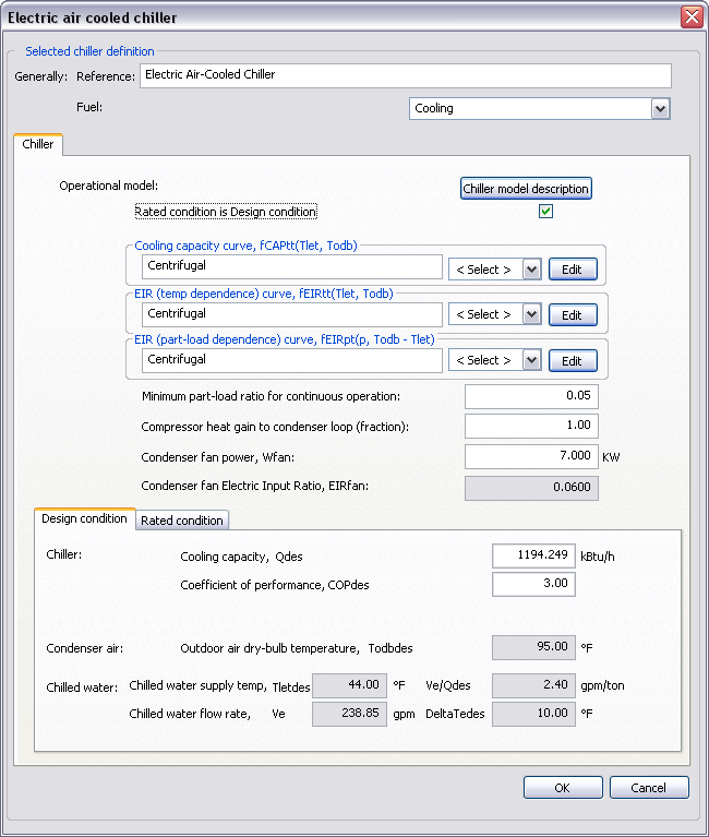 Design Condition
 Figure 3 - 116 : Electric air-cooled chiller dialog showing design condition tab when “Rated condition is Design condition” tick box is ticked. When this is un-ticked, the inputs for Cooling capacity and COP are no longer edited here, but are editable in the Rated condition tab.
Outdoor air dry bulb temperature, Todbdes
The design outdoor air dry bulb temperature is specified in the associated chilled water loop dialog (in the Heat rejection tab) and is displayed here as a derived parameter.
This parameter is autosizable. When this parameter is autosized, its value in the field and its autosizing label ‘A’ become green.
Chilled Water Supply Temperature, Tletdes
The design chilled water supply temperature (leaving evaporator water temperature) is specified in the associated chilled water loop dialog (in the Chilled water loop tab) and is displayed here as a derived parameter.
Chilled Water Flow Rate, Ve, Ve/Qdes, ∆Tedes
V e , V e /Q des and ∆T edes are three different options for specifying design chilled water flow rate. Currently it is specified in terms of ∆T edes (the difference between the design chilled water return and supply temperatures). It is specified in the associated chilled water loop dialog (in the Chilled water loop tab) and is displayed here as a derived parameter. The other two options (V e and V e /Q des (the ratio between design chilled water flow rate (V e ) and design cooling capacity (Q des ).) are automatically derived by the program based on the specified ∆T edes and cannot be edited.
Cooling Capacity, Qdes
When ‘Rated condition is design condition’ is not ticked, the design cooling capacity is automatically derived by the program using other design and rated condition data provided and does not need to be edited.
When ‘Rated condition is design condition’ is ticked, enter the design cooling capacity.
This parameter is autosizable. When this parameter is autosized, its value in the field and its autosizing label ‘A’ become green.
Coefficient of Performance, COPdes
When ‘Rated condition is design condition’ is not ticked, the design coefficient of performance is automatically derived by the program using other design and rated condition data provided and does not need to be edited.
When ‘Rated condition is design condition’ is ticked, enter the design coefficient of performance.
Rated Condition
‘Rated condition’ and ‘Design condition’ are provided for flexibility in specifying chiller data.
The rated condition is the basis for the calculation of chiller characteristics at simulation time. The rated condition is usually the rated or ARI condition – i.e. the condition at which the chiller characteristics are specified by a manufacturer. However, it can optionally be the design condition.
The default rated condition data are based on the standard ARI conditions (ARI Standard 550/590-2003): 44 o F leaving chilled-water temperature, 95 o F outdoor air dry bulb temperature, 2.4 gpm/ton evaporator water flow rate. Here ‘/ton’ means ‘per ton of refrigeration delivered to the chilled water’.
The design condition, on the other hand, is the condition applying at the time of design peak chiller load.
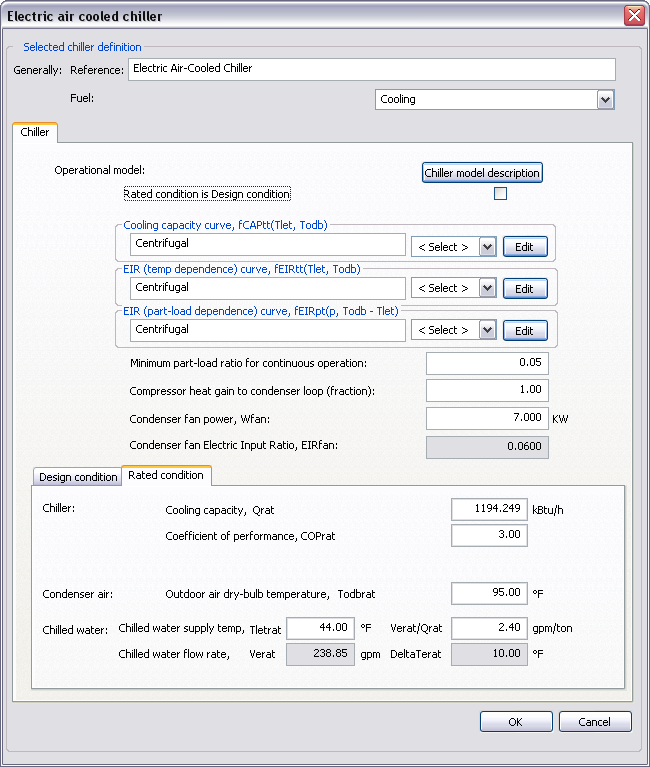 Figure 3 - 117 :
 Electric air-cooled chiller dialog showing Rated condition tab when “Rated condition is Design condition” tick box is not ticked. The white fields in the Rated condition tab are editable when not set equal to the design conditions.
A user wishing to use catalogue chiller data enters a capacity and COP at the rated condition and reads off the derived capacity and COP at the design condition.
A user wishing to size a chiller based on a design load enters a capacity and COP at the rated condition, then adjusts the capacity to produce the desired derived capacity at the design condition (allowing for a margin of over-sizing).
If the rated condition and design condition are one and the same, the user ticks the checkbox of ‘Rated condition is design condition’, which makes the rated condition data a dynamic copy of the design condition data.
The derivations of chiller capacity and COP are done using the user-entered performance curves and other data.
Outdoor air dry bulb temperature, Todbrat
When ‘Rated condition is design condition’ is ticked, the rated outdoor air dry bulb temperature is a dynamic copy of the design outdoor air dry bulb temperature.
When ‘Rated condition is design condition’ is not ticked, enter the rated outdoor air dry bulb temperature.
Chilled Water Supply Temperature, Tletrat
When ‘Rated condition is design condition’ is ticked, the rated chilled water supply temperature (leaving evaporator water temperature) is a dynamic copy of the design chilled water supply temperature.
When ‘Rated condition is design condition’ is not ticked, enter the rated chilled water supply temperature.
Chilled Water Flow Rate, Verat, Verat/Qrat , ∆Terat
V erat , V erat /Q rat , and ∆T erat are three different options for specifying rated chilled water flow rate. Currently it is specified in terms of the ratio between rated chilled water flow rate (V erat ) and rated cooling capacity (Q rat ). The other two options (V erat and ∆T erat (the difference between the rated chilled water return and supply temperatures)) are automatically derived by the program based on the specified V erat /Q rat and cannot be edited.
When ‘Rated condition is design condition’ is ticked, the rated chilled water flow rate is a dynamic copy of the design chilled water flow rate.
When ‘Rated condition is design condition’ is not ticked, enter the rated chilled water flow rate.
Cooling Capacity, Qrat
When ‘Rated condition is design condition’ is ticked, the rated cooling capacity is a dynamic copy of the design cooling capacity.
When ‘Rated condition is design condition’ is not ticked, enter the rated cooling capacity.
Coefficient of Performance, COPrat
When ‘Rated condition is design condition’ is ticked, the rated coefficient of performance is a dynamic copy of the design coefficient of performance.
When ‘Rated condition is design condition’ is not ticked, enter the rated coefficient of performance.