Dialog sections and tabs in general
The System Parameters dialog has eight main sections, each dealing with a different aspect of system data: Common system-level configuration and edit functions at the top; access to Zones Tabular Edit and basic copy, paste, save, and assign functions at the bottom; and six tabs for detailed editing of system and zone data.
System Parameters dialog tabs
The System Parameters dialog includes the following six fixed tabs:
· Schedules
· System Parameters
· Zone Temp, Humidity & Equipment
· Zone Ventilation & Exhaust
· Zone Loads & Supply Airflows
· Zone Airflows, Turndown & Engineering Checks
Schedules tab
For VE2016, this tab simply provides access to and mirrors values entered in the System Schedules dialog; in the next phase of implementation it will replace the separate System Schedules dialog.
System Parameters tab
This tab provided inputs and settings relating to the system as a whole.
· Data relating to the component and controls in the system air handling unit (AHU), including autosized and editable parameters for optional system-level features, such as alternate OA damper configurations and controls, 100% OA system, indirect or direct evaporative cooling, selection of cooling and heating sources for system-level coils, etc.
· This is a system-level tab for any mutli-zone system, and is a zone-level tab for packaged single-zone systems, and also for packaged terminal air-conditioning and heat-pump equipment (PTAC and PTHP) when these are provided as terminal units only (no dedicated outdoor air system or DOAS within the same system frame).
Zone Temp, Humidity & Equipment
Zone HVAC temperature setpoints (same for entire system in phase 1), humidity control options and setpoints, and basic inputs for zone-level coils.
Zone Ventilation & Exhaust
Parameters required for a broad range of zone ventilation calculation methods, including user-specified, ASHRAE 62.1, demand-controlled ventilation, and maximum of multiple requirements. The air changes and exhaust section provides inputs parameters primary air-change and exhaust requirements, including make-up air options (primary, transfer, or a mix) and standards such as ASHRAE 90.1 PRM and 170.
Zone Loads & Supply Airflows
Autosized zone airflows, oversizing factors, manual input overrides, option to address latent cooling loads, option for dual-maximum VAV controls, and reduction of required airflow if a room unit is also present.
Zone Airflows, Turndown & Engineering Checks
Zone area, occupancy, and loads (after any user-enter oversizing), final cooling and heating design maximum airflows, VAV turndown, VAV control type, minimum primary airflow, terminal unit fan control options and recirculated airflows, and summary of all relevant autosized zone and system airflow rates. This includes typical engineering checks, OA % at min and max primary airflow, etc.
A Zones Tabular Edit dialog can be launched from the System Parameters dialog or directly from the toolbar to edit the same parameters for all zones on a system in a configurable spreadsheet-like view.
Zones Tabular Edit dialog tabs
This separate window, accessed via buttons on the toolbar and within the System Parameters dialog, provides a spreadsheet-like dialog with customizable columns and tab for viewing and editing system data. With the exception of System Schedules, which are not included here, the Zones Tabular Edit dialog provides access to all of the same parameters that are visible and/or editable in the System Parameters dialog; however, there is an added loads summary tab and some tabs are subdivided to make the number of columns manageable.
· Loads Data
· System Parameters
· Zone Temp, Humidity & Equipment
· OA Ventilation
· Air Changes & Exhaust
· Cooling Airflows
· Heating Airflows
· Zone Design Airflows
· Engineering Checks
Loads Data
Basic zone data, including dimensions, loads, setpoints, etc., upon which sizing of zone airflows and room unit water flow rates will be based.
System Parameters
System-level parameters, with one system per row (layer) in the case of single-zone systems, and all rows being forced selected and edited as one in the case of multi-zone systems.
Zone Temp, Humidity, Equip
Same data as on Zone Temp, Humidity & Equipment tab in System Parameters dialog.
OA Ventilation
Same data as Outdoor air ventilation plus Demand-controlled ventilation (DCV) sections on the Zone Ventilation & Exhaust tab in the System Parameters dialog.
Air Changes & Exhaust
Same data as Air-change requirements, exhaust, and transfer air section on the Zone Ventilation & Exhaust tab in the System Parameters dialog.
Cooling Air & Water Flows
Same data as Cooling loads and air supply for space conditioning plus Cooling loads for zone-level terminal units or room units (DCV) sections on the Zone Loads & Supply Airflows tab in System Parameters dialog.
Heating Air & Water Flows
Same data as Heating loads and air supply for space conditioning plus Heating loads for zone-level terminal units or room units (DCV) sections on the Zone Loads & Supply Airflows tab in System Parameters dialog.
Zone Design Airflows
Same data as Zone heating & cooling airflows, turndown, and engineering checks section on the Zone Airflows, Turndown, & Engineering Checks tab in the System Parameters dialog.
Engineering Checks
Summary of data from previous tabs of the Zones Tabular Edit dialog, with a few additional units formats, such ft2/ton for cooling load.
Customizing tabs in Zones Tabular Edit dialog
All tabs in the Zones Tabular Edit dialog can be customized in terms of the columns are included. Standard tabs can be hidden, and new tabs can be added to access, edit, or export a preferred set of columns.
Saved custom tab configurations can be copied to another machine by copying the following file, which is normally located in Users > user name > AppData > Local > IES: tab_asimview_zone.cfg
Tab behavior
The System Parameters and Zones Tabular Edit dialogs store the tab and sub-tabs selection when they are closed, and this tab selection is thus re-instated then next time the dialog is open. This is true the even when moving between systems on the canvas or separate ApacheHVAC files. This allows for successively viewing or editing the same parameters for multiple systems without having to switch tabs each time the dialog it opened. When staying within a single ApacheHVAC file, the dialog can also be opened from the toolbar for editing multiple systems without leaving the dialog.
Grayed-out parameters
Parameters and options on the dialog are grayed out if the necessary parameter link does not exist in the HVAC network within the system frame.
A Tooltip is provided upon hovering over a parameter that is grayed out as a result of a missing link. The ToolTip text lists the links that will enable the parameter and the type of component or controller and controlled variable for which they are available.
While some labels do change with links and settings, the parameters included in the System Parameters dialog are essentially fixed for all system types. Any that are not universal, and thus may not be relevant to a particular system or configuration, are grayed out when the parameter link is not present.
Each feature of a pre-defined prototype system includes both a component or controller and the necessary parameter link; however, only the link is required to enable the parameters in the dialog and thus also to transfer the associated values to the component or controller in which then link has been set.
Coloring of text and fields for data source or status
Text color is used to provide information regarding the data sources or status for various values in the System Parameters and Zones Tabular Edit dialogs. If desired, the default colors below can be revised via ApacheHVAC > Preferences… > Integrated System Management > Colors, or Preferences toolbar button.
Color of values to indicate data source or status:
· Black = general default or user-edited value when the edit is applied to all zone-level layers; User-edited value in all system-level dialogs.
· Orange = value changed for a single zone or subset of zones—.e., when not all layers are selected; black when all layers are the same value or edited together to maintain consistency across layers.
· Magenta = from Space Data and not yet edited in ApacheHVAC.
· Light blue = a default load, capacity, or airflow value that will be directly autosized when either Zone-level or System-level sizing is completed; these are generally also user-editable values.
· Green = directly autosized load, capacity, or airflow that has not been edited since autosizing. In other dialogs, such as for chilled or hot water loops, these may derived from an autosized value not edited since autosized; in the System Parameters and Zones Tabular Edit dialogs, however, green is applied only to directly autosized values, given there are numerous other values derived from these.
· Red = error condition that must be revised before simulation can proceed. The problem value, name of the layer to which it belongs, and label of the dialog tab on which it appears all turn red to aid in locating the source of the error. The system frame for the HVAC network also turns red so that systems with an error can be readily located in an ApacheHVAC file of multiple systems. The ToolTip provided when hovering over the system frame lists the specific parameters that are in error.
· Light grey = parameter that is not available without the addition of required components and/or system parameter links that enable it. In the System Parameters dialog, parameters are grayed out and disabled when the required link or links are not present within the system frame. Hovering over any parameter that is disabled for this reason provides a ToolTip listing the required links and type of component or controller that they apply to. If a parameter is disabled and there is no such ToolTip, this is because the parameter must be enabled by other means (a checkbox in the dialog, a particular system configuration, or another parameter upon which it depends).
Values are green to indicate autosized status in the following cases:
· All capacity values (kW or kBtu/h) are green after autosizing if directly autosized and until they are edited or caused to change by way of derivation.
· All capacity values (kW or kBtu/h) derived directly from autosized values inherit the green/black autosize status of the autosized value they are linked to whenever the link is enabled. So long as they are linked and the source value remains green, they must remain green.
· For non-capacity values, such as water flow rate, just the black “A” turns green when the value is derived from a currently green autosized capacity.
Conditional formatting of data fields:

Very-light grey background indicates a disabled field (it will have grayed-out text).

Medium-light grey background indicates a field containing uneditable derived values.

Pale yellow background is used for fields containing user-editable (input) values.

Dark yellow marks the lowest zone-level ASHRAE 62.1 Ventilation Efficiency value on a system, and therefore indicates the “critical zone” (or zones) on that system.

Conditional formatting of zone OA fraction cells in Zones Tabular Edit dialog to indicate greater or lesser influence on the required system minimum outside air for ventilation.

Green is used to draw attention to a field such as ‘Min OA req as fraction of min supply airflow’, when the value in the field is outside of a typical range, and this is expected as the outcome of ‘Demand controlled ventilation’, such that the unusual value is likely acceptable and desirable.

Dark orange is used to draw attention to a field such as ‘Min OA req as fraction of min supply airflow’, when the value in the field is of potential concern—i.e., outside of a typical range.
Dark orange is also used for any parameter within a multiplexed component or controller for which a ‘touch edit’ has been executed by double-clicking the field when in a global-edit mode (‘All selected layers’ or ‘All layers’). The orange color indicates that the double-clicked value displayed in the field
has been copied to all other selected layers, and this will be saved to those layers upon clicking ‘OK’ in the current dialog. Accessing the Tabular Edit (Data Table) view for the parameter to confirm the data has been temporarily copied to all, as it will be saved on ‘OK’.
Controls and information on the common sections of the System Parameters dialog
System to edit
The ‘System to edit’ field displays the system name from the system frame.
When the System Parameters dialog is launched by double-clicking the top bar of the system frame, the displayed ‘System to edit’ will be an editable duplicate of the complete text displayed on the system frame (excluding the system type code, such as ‘09a’). When the System Parameters dialog is closed, the system name will be updated if changes were made.
When the System Parameters dialog is launched via the toolbar, the ‘System to edit’ field becomes a drop-down menu of system names to choose from, supporting sequential editing of multiple systems without leaving the dialog. The system name displayed here is an editable duplicate of the complete text displayed on the system frame. A ‘Rename’ button to the right of the drop-down selector provides for editing the selected system name in this mode (all but the system type code, such as ‘09a’, is editable).
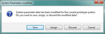
When launched from toolbar, attempting to change the 'System to edit' selection to another system when there are any unsaved or unassigned changes will open a pop-up window with the following message:
Enable sizing
When the ‘Enable sizing’ checkbox is checked, the values in the system parameters dialog for the current system to edit will be updated upon running either zone- or system-level sizing. This assumes that in the ASHRAE Loads dialog the checkbox to update ApacheHVAC systems is also checked, which applies to all systems in the selected ApacheHVAC file.
When the ‘Enable sizing’ checkbox is unchecked, the values in the system parameters dialog for the current system to edit will not be updated upon running either zone- or system-level sizing (regardless of the setting in the ASHRAE Loads dialog).
Layer edit mode
The ‘Layer edit mode’ buttons function like radio buttons (one of the three must be selected) and determine the influence of changes made on any of the Zones tabs.
There are three layer edit modes:
1) ‘Current’ = edits will apply only to the currently selected display layer.
2) ‘All Selected’ = edits apply all selected layers. Access Edit Multiplex dialog to change the selection set.
3) ‘All’ = edits apply all layers in the multiplex.
ToolTips are also provided for these ‘Edit modes’.
Change the ‘Layer edit mode’ in the System Parameters dialog also sets this in the Edit Multiplex dialog.
Edit Multiplex button
This button provides access the Multiplex Edit dialog to assign zones to layers and change layer selections, etc., without leaving the System Parameters dialog. When using this nested access to the Edit Multiplex dialog, any changes—selection set, local vs. global edit, addition or deletion of layers, assignment of zones to layers—must be accepted or discarded prior to returning to the System Parameters dialog to continue editing there.
SI/IP selector
This drop-down units selector changes the units from Standard International (SI) or Metric units to Inch-Pound (IP) or Imperial units for all values in the System Parameters and Zones Tabular Edits dialogs, independent of the units setting for the current VE model editing session.
Configuration
The ‘Configuration’ field provides basic information regarding the selected configuration. One of the two buttons for CAV or VAV must be selected (like radio buttons) to determine airflow control options that affect other elements of the dialog and system controls. A ‘Two speed fan’ check box is enabled as a sub-option for CAV when configuration is ‘Packaged single zone systems’.
Configuration, as determined by the software:
· Multi-zone system with AHU : default for all systems other than those that trigger options below.
· Multi-zone system with D OAS: displayed if either “DOAS vent airflow” or “DOAS vent airflow CAV/DCV” system parameter link is present.
· Single-zone systems : displayed when all system parameter links AND all air inlets and outlets in system frame are within the multiplex.
· Packaged terminal units : displayed when all sys parameter links in system frame are within the multiplex AND no air inlets or outlets are within the multiplex.
These configurations enable or set the behavior for many parameters within the System Parameters dialog.
For ‘ Single-zone systems’ and ‘Packaged terminal units’ configurations there is one system per layer in the multiplex, and therefore the ‘System Parameters’ tab of the dialog can and normally should have distinct values for each layer in the multiplex. In other words, because these are ‘single-zone’ system types, and each layer represents a zone, the ‘system-level’ parameters are present for each individual zone, and thus for each multiplex layer.
Configuration – VAV or CAV and Two-speed fan
As a subset of the four fundamental system configuration categories described above, there are user-selectable options for Variable-Air-Volume (VAV) vs. Constant-Air-Volume (CAV), and a sub-option for using a two-speed fan in CAV packaged single-zone systems.
-
Variable air volume (VAV): Supply and Return Fan curves are enabled, and normal calculation of Min and Max airflow for zones is used throughout the System Parameters dialog. VAV options such as ‘dual-maximum’ VAV control are enabled.
-
Constant air volume (CAV) system : Supply and Return Fan curves are disabled, and zone Min airflows are set equal to zone Max airflows (excepting for DOAS systems—see below).
In the case of DOAS systems (when either the ‘DOAS vent airflow’ or ‘DOAS vent airflow CAV/DCV’ link is present) the CAV setting influences only the DOAS maximum primary airflow to zone. The inclusion of demand-controlled ventilation (DCV) for any one zone can override a system-level CAV setting, just for the zone with DCV. In other words, the DOAS minimum primary airflow to any given zone may be varied by DCV controls, if the link is present and that options is selected. The determination of terminal unit CAV vs. VAV for heating and cooling is handled by the ‘Terminal unit fan
control (FCU or FPB)’ options setting.
-
Two-speed fan: checkbox is enabled if either the ‘PSZ Cooling airflow CV/2sp/VAV’ or ‘PSZ Heating airflow CV/2sp/VAV’ link is present.
-
The following system parameter links indicate a controller subject to these settings, and the settings apply to all zones in a given system network:
-
-
-
PSZ Cooling airflow CAV/2sp/VAV
-
PSZ Heating airflow CAV/2sp/VAV
-
FPB Primary airflow CAV/VAV
-
DOAS vent airflow CAV/DCV (with noted exception for any zone wherein DCV is engaged)
-
Act bm/IU Primary air CAV/VAV cool
-
Act bm/IU Primary air CAV/VAV heat
-
-
-
The ‘2-speed fan’ option applies only to the system-level control in Packaged Single-Zone systems
-
Active beam/induction units have a zone-level override for setting some zones to CAV on a VAV system (see below), but not the other way around (see below).
-
Constant, 2-speed, and variable fan operation for FCU (Fan-Coil Unit) and FPB (Fan-Powered Box) fans are set using the ‘Terminal unit fan control (FCU or FPB)’ selector on the last tab of the dialog.
-
The airflow controller links listed above are available only in independent controllers with sensor. So long as proportional control is enabled in the controller, VAV and CAV options are available.
For VAV, 2-speed, and CV links, changing the configuration setting in the System Parameters dialog will change the values written to the controller, as described below:
-
Cooling airflow — All controls: Flow rate at max sensed signal = Cooling maximum primary airflow (see rules described in the info icon note for determining Cooling maximum primary airflow).
-
CAV: Flow rate at min sensed signal AND Flow rate at max sensed signal = Cooling maximum primary airflow.
-
Heating airflow — VAV and 2-speed controls: Flow rate at min sensed signal = Heating maximum primary airflow (see Heating maximum primary airflow info icon note regarding rules for determining this value).
-
CAV: Flow rate at min sensed signal AND Flow rate at max sensed signal = Heating maximum primary airflow.
-
For controls with 2-speed option: Flow rates are same as described above for VAV Cooling and Heating.
-
If 2-speed, Proportional bandwidth in the controller is set to 0.1°F (small non-zero value).
-
If changed back to VAV, Proportional bandwidth in the controller is set back to default 2.0°F for ISM phase 1 (in phase 2, the “throttling range” setting will determine this value).
-
VAV: Proportional bandwidth in the controller is pre-set to 2.0 °F by default, but not via the link. This value will be user-adjustable for all controllers on the system via the “throttling range” setting in ISM phase 2 interface, but for phase 1 remains manually set at 2.0 °F and thus editable only via the controller dialogs and tabular edit view for those dialog.
-
IF Configuration = Single Zone Systems OR Packaged Terminal Units, the VAV/CAV setting is specific to the currently selected layer(s). When multiple layers with differing settings for this control are currently selected, both buttons remain active and both should are blue. Clicking VAV will make all currently selected layers VAV. Clicking CAV will make all currently selected layers CAV.
-
IF Configuration = Single Zone Systems AND supply fan Reference = S2: PRM Baseline Supply Fan (both with or without the “S2:”, which will be removed at some point), the current layer is switched from VAV to CAV as follows:
-
Autosized DX Cooling Coil cooling capacity > 110KBtu/h = VAV
-
Autosized DX Cooling Coil cooling capacity ≤ 110KBtu/h = CAV
-
The DOAS vent airflow link for time switch controllers simply uses the value for DOAS max primary airflow to zone
, as this type of controller has no possibility of varying the flow rate.
-
When the DOAS vent airflow CAV/DCV link is detected, the values to be written to the controllers will normally be the CAV (=DOAS max primary airflow to zone for both max AND min) unless there are DCV settings for a particular zone in the Ventilation tab. When DCV is enabled, the ventilations air to the zone varies between high and low values accordingly. In other words, the setting of Demand controlled ventilation on the Zones Ventilation & Exhaust tab takes precedence over the CAV default for any individual zone, as follows:
o If no DCV for a zone (thus constant ventilation rate), set both Flow at min sensed signal and Flow at max sensed signal = MAX(“ Zone ventilation max/total req” l/s (cfm) column, Exhaust – Transfer Airflow).
o If DCV is enabled for any given zone (thus variable ventilation rate), flow at min sensed signal is set according to DCV options, as described in Ventilation tab section of this specification.
-
Active beam/induction unit controls
o When Act bm/IU Primary air CAV/VAV cool or the Act bm/IU Primary air CAV/VAV heat link is detected:
-
The system-level control is for the system. When the system is CAV, all zones must be CAV. When the system is VAV, the zone default is VAV, but selected zones can be changed to CAV or from that back to VAV—but only via the Active beam or induction unit primary airflow control: [ CAV | VAV ▼ ] control in the lower part of the dialog).
-
Selecting CAV at the system level (here) disables the Active beam or induction unit primary airflow control: [ CAV | VAV ▼ ] control on the last tab of the System Parameters UI, and sets that control to CAV for ALL zones. The user cannot change this for any zone.
-
Selecting VAV at the
system level (here) enables the Active beam or induction unit primary airflow control: [ CAV | VAV ▼ ] control on the last tab of the System Parameters UI, and sets
that control to VAV for ALL zones. The user can then selectively change some zones to CAV, leaving others at VAV for a system that has both.
Current layer
The ‘Current layer’ selector set the current display layer for viewing and editing. Setting this within the System Parameters dialog changes the same setting on the multiplex section of the ApacheHVAC toolbar.
As with the editing of any multiplex components and controls, edits to the ‘Current layer’ will apply to additional layers is the ‘Layer edit mode’ is set to ‘All’ or ‘All selected’ (and other layers are selected).
Zones Tabular Edit
The ‘Zones Tabular Edit’ button opens that separate dialog for editing the full range of values in the System Parameters dialog in a user-configurable spreadsheet like format.
Copy and Paste
Copy and Paste buttons provide capability for copying data between systems or layers (zones), for example, by selecting a current layer, clicking Copy, then changing the current layer and clicking Paste. All unique values and settings on the copied tab will be pasted to the receiving tab.
The Zones Tabular Edit dialog supports Copy (export) of all data with column headings for any given tab. After editing in a spreadsheet, revised data can be pasted back into this dialog, provided that the data columns are placed adjacent to each other and to the layer numbering column, which must be included in the copied selection, along with data and column headings. See sec 4.3 Import data to Zones Tabular Edit.
Save, Assign, or Cancel
There are four buttons for discarding or applying changes:
-
Cancel = discard changes and exit the dialog.
-
Save & Exit = save changes and exit the dialog.
-
Assign = assign changes to system components and controllers and stay in the dialog. If launched from the toolbar, this applies to the currently selected ‘System to edit’.
-
Assign & Exit = assign changes to components and controllers and exit the dialog.
‘Assign & Exit’ is equivalent to the ‘OK’ button in most other ApacheHVAC dialogs and VE modules, but is more explicit with respect to applying values not yet applied.