Components are used in MicroFlo to act as:
A. Sources of heat, water vapour, carbon dioxide or carbon monoxide
B. Obstructions to the flow
C. As ‘mounting’ surfaces for boundary conditions.
When they are used for purposes defined in point A, they are classed as ‘Source Components’. When they are used for purposes defined in points B and C, they are classed as ‘Solid Components’.
Components are applicable for internal simulations only.
Setting up a component for use in MicroFlo
Before a component can be used in MicroFlo, it needs to be set as such. Following procedure is used to make the component usable in MicroFlo:
1) Go to ‘Components’ in the applications list of VE.
2) Create/Import the components you want to use.
3) Ensure that the components you have created are manifold 3D components. MicroFlo does not accept 2D components.
4) After you are finished creating/importing the component, select the component in the component browser list.
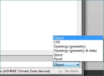
5) At the bottom right corner, you will see a drop-down box ‘Object’.
6) Click on this and set this to ‘CFD’
Figure 4-1: Component setup for MicroFlo
7) Now this component is available for use in MicroFlo.
8) Repeat if necessary for more components.
Place Component Dialogue box
Components can only be placed in one of the orthogonal views of the model. To place a component:
A. Ensure you are in room level of decomposition of the model
B. Select one of the orthogonal views.
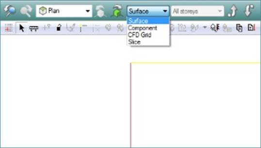
C. Switch view from ‘Surface’ to ‘Component’ mode in the list of display modes at the top.
Figure 4-2: Switching from Surface to component mode
D. Click on the ‘Place Component’ button (

) on the MicroFlo toolbar. This will bring up the ‘Place Component dialogue box as shown in Figure 4-3.
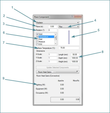
Figure 4-3: 'Place Component' Dialogue box
The ‘Place Component’ dialogue box is divided in the following parts:
1. Drop list of the various components available for use in MicroFlo
2. Plane: Height above the datum where the component is to be placed. Note that this is the absolute level for the component. E.g. if the floor of the room is 10m above the origin, selecting plane = 10m in plan-view will place the component on the floor of that room.
3. Rotation: Specifies the rotation applied to the component in counter clockwise direction about Z-axis when placing the component.
4. Drop down box to select the view of component before placing it in the model. This is a visual aid only.
5. Window showing the component in the view selected in the drop down described in item 4 above.
6. List of various properties that can be applied to the components
7. Value of the selected property to be applied to the component
8. Dimensions: The component can be scaled in individual directions to suit the requirement providing re-usability of components. The scale can be adjusted by changing the value of X/Y/Z scales or directly changing the value of the Length/Depth/Height of the components
9. Room Heat Gains: This is same as already described in
section 3.2 for Boundary Condition dialogue box.
E. After all the properties have been appropriately set, hover over the model with the mouse. You will see the component hovering along with the mouse pointer.
F. Click in the location where you want to place the component.
G. If needed, the component can be moved/copied/rotated using the appropriate options on the MicroFlo Toolbar.
Using Components as Sources
Source components are used for adding volumetric sources of heat, moisture, CO2 or CO. Such components do not obstruct the flow and can be termed as hollow components. To place a component as a source follow the following procedure:
2) In step E, untick the box which says ‘Solid’.
You can now add sources of heat in W, moisture, CO2 and CO in kg/hr to this source component. You cannot temperature to this component as this is a surface property and as such this component has no surface.
Using Components as Solids
Solid components are added to provide a suitable obstruction to the flow. These components can also additionally have a heat or temperature boundary assigned to them. To place a component as a solid follow the following procedure:
2) In step E, tick the box which says ‘Solid’.
You can now assign temperature or heat to this solid component. You can only assign one of these two properties to this component as when one of these is defined the other is a derived quantity.
Solid Components with boundary conditions
The solid components can be further enhanced to add boundary conditions on the surface of the component. To do this, when adding a solid component do not add a temperature or heat condition to the component. Place it just as a plain solid obstructing the flow. This will automatically apply a zero-gradient heat condition to the component.
Now, navigate to the surface of the component just as you would for a room. Apply the appropriate boundary condition as per your requirement on the surface of the component as described in
section 3.3 and
section 3.4. Interface boundary conditions cannot be applied as they can be only applied to the hole between two rooms of a multi-zone space.
Also ensure that you don’t apply boundary condition to a surface that is coincident on a surface of the domain. This will cause the boundary condition to not take part in the simulation. E.g. if you apply an extract boundary on the face of the component lying on the floor, MicroFlo will assume the flow is balanced, but the actual flow will be imbalanced and the solution will diverge.