ASHRAE Loads and ApacheHVAC System Sizing
ASHRAE Loads
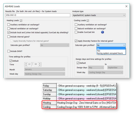
ASHRAE Loads supports flexible user control and differentiation between Room & Zone Loads, System Loads, and Dynamic Simulation. The following can be independently determined for the different types of loads analyses, with settings for each being retained by the software:
-
Inclusion of internal gains;
-
Diversity for internal gains;
-
Saturation of profiles for internal gains, and if so, during all hours of non-zero profile values or just during occupied hours;
-
Use of Design Day profiles when specialized gain profiles are needed specifically for Loads Analyses;
-
A separate setting for inclusion of Diversity factors in dynamic simulations is provided in the ApacheSim dialog.
The user settings above are retained as user preferences for future loads and simulation runs.
Figure 1 - 15 : ASHRAE Loads dialog utilizing Design Day profiles with Diversity applied to internal gains
System Sizing
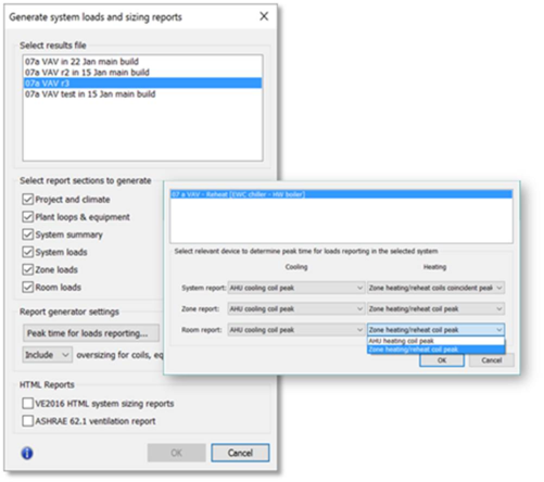
A consolidated “Generate system loads and sizing reports” dialog provides one place to generate a broad range of new and existing reports for buildings, system, zone, and room loads, sizing, and ventilation. This provides user control over:
1. The results file to be used for generating reports;
2. Which of the new PDF Loads reports will be generated;
3. Selection of the relevant coils for reporting of gains and losses contributing to coil loads at the time of the coil peak;
4. The inclusion or exclusion of oversizing factors, which will be indicated one way or the other on the reports generated.
Available reports include:
-
Project and climate (building, weather, etc.)
-
Plant loops & equipment (capacity, flows, etc.)
-
System summary (space loads & ventilation)
-
System loads (detailed loads breakdown, coil capacities, airflows, engineering checks, etc.)
-
Zone Loads (same as for System)
-
Room Loads (same as for Zones)
-
VE2016 System Sizing reports
-
ASHRAE 62.1 Ventilation (App. A method)
Figure 1 - 16 : Generate system loads and sizing reports dialog with relevant peak settings shown
1.1 Domestic Hot Water modeling
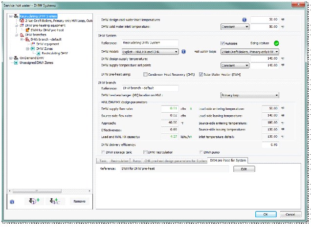
ApacheHVAC offers an explicit model for heating domestic hot water (DHW) cold inlet water using a hot water loop, condenser heat recovery, solar water heating, and/or a hot water loop heat exchanger.
Figure 1-18: Service hot water - DHW Systems dialog for editing domestic hot water parameters and zone assignments within ApacheHVAC
The Service hot water – DHW Systems dialog shown in Figure 1-18 defines DHW Systems and DHW Branches on a tree on the left, with parameters to specify systems on the right. The tree allows drag-and-drop functionality to assign DHW Zones to DHW Branches. Multiple DHW Branches may be added to a DHW System using the add button at the bottom. Assigning DHW Zones to DHW Branches assigns DHW Zones to the associated DHW System. Multiple DHW Systems may be added to a project using the add button at the bottom. Only DHW Zones with a setting for demand at the DHW Zone level or containing Rooms with ApacheHVAC DHW demand will be shown in the DHW Systems dialog.
Parameters for defining the DHW System are on the right and specify either a simple or explicit DHW model. The Explicit model couples the DHW tank to any hot water loop via a heat exchanger model and provides for optional pre-heating via an explicit condenser heat recovery heat exchanger model. The Simple DHW loads model can be used with a hot water loop or generic heat source, but does not include the explicit heat exchanger or the optional condenser heat recovery pre-heating.
HVAC System, Node, and Component results
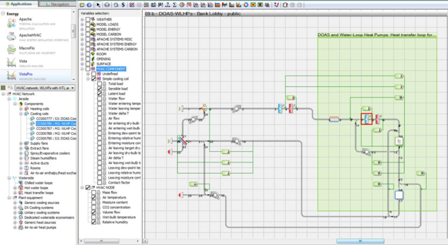
Simulation results for detailed HVAC system modeling in ApacheHVAC can be viewed and analyzed in both Vista and Vista-Pro modules. In addition to the model-level system results and more detailed room-level results, the standard Vista results view offers access to results for airside HVAC network nodes (essentially as shown in VistaPro, below) as well as node-based results for a small number of s.
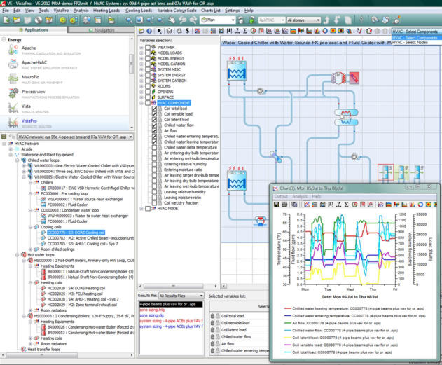
VistaPro provides access to all HVAC results, including those associated with thermal zones (rooms or other spaces in the model), nodes on the airside HVAC network, components on both airside and waterside networks, and all HVAC plant equipment.
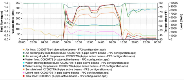
Figure 1 - 17 : Selected results for two airside network nodes and a cooling coil component in VistaPro.
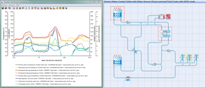
Figure 1 - 18 : Selected results for a chilled water loop, chiller, and fluid cooler in VistaPro.
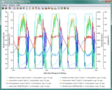
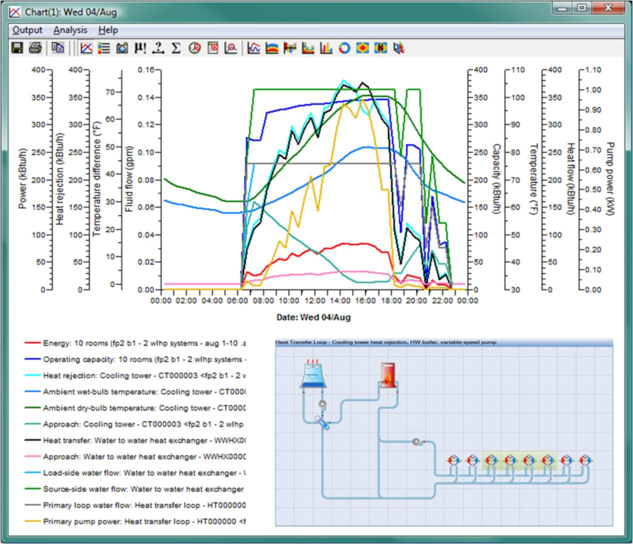
Figure 1 - 19 : Detailed component-level results can be analyzed over the course of a day to understand the influence and interactions of water- and air-side system configuration and control options.
Figure 1 - 20 : When a particular component is selected on the waterside component browser tree in VistaPro, the appropriate set of component output variables becomes available for that component.
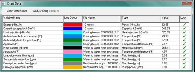
Figure 1 - 21 : Component variables can be locked via the Chart Data dialog (access by clicking the plot area) to include many details on a single plot. Above, energy and operating capacity for ten water-loop heat pumps have been plotted with select performance parameters for the heat exchanger and cooling tower used to reject heat from the heat pumps and the common heat transfer loop that couples them.