System Modeling Fundamentals
Preparation
The speed, efficiency, and effectiveness with which an ApacheHVAC system can be set and all thermal zones assigned to it is significantly dependent upon the extent to which the model has been appropriately organized prior to doing so. Therefore, it is important to complete the following in ModelIt, before attempting to assign rooms or zones to an ApacheHVAC system:
-
Begin by using the Connect Spaces tool to couple any rooms in the model that will share a common thermostat or related means of controlling space conditions (e.g., they will all be served by a single VAV box). The resulting thermal zone will thus be represented as a single “Room” component in ApacheHVAC. This will facilitate use of multiplexing, pre-defined systems, and efficient system layout, while avoiding unnecessary complexity.
-
When connecting spaces, if they will be separated by physical partitions in the actual building, these partitions should be retained, as their thermal mass and ability or receive solar gain or other radiant, conductive, and convective heat transfer will contribute to the accuracy of thermal and energy modeling.
-
If any of the zones has absolute internal gains (W or Btu/h) rather than internal gains defined according to floor area (W/m
2 or W/ft
2), the absolute gains will have to be manually added in the composite zone. However, if they are assigned per unit floor area, no action is required, as no floor area will be lost.
-
In addition to conditioned spaces, create geometry for any other spaces or zones that will need to be represented in ApacheHVAC, such as return-air plenums (typically one per floor or as designed), underfloor air distribution (UFAD) supply plenums, thermally stratified zones, radiant heating or cooling slabs, earth tubes, solar chimneys, etc.
-
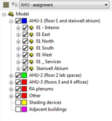
It is important to set up a Grouping Scheme in ModelIt that sorts thermal zones into groups such as System-1, -2, -3, etc. or AHU-1, -2, -3, etc. and other space types, such as Return air plenums, Solar chimney segments, Unconditioned zones, etc.
-
If the model includes UFAD of thermal displacement ventilation (DV), it is essential to ensure that the number and order of Stratified zones exactly matches the number and order of corresponding Occupied zones in any one AHU group. Doing so will facilitate system multiplexing, autosizing, and other fundamental aspects of system modeling. If there are some mixed (non-stratified zones) on the same system, either place them in a separate group of occupied zones or create dummy stratified zones (e.g., a series of small super-insulated boxes with no internal gains) in the model that can fill out the list of stratified zones to make it parallel the list of occupied zones on the same system. Occupied and Stratified should be in separate groups with the AHU Assignment scheme.
Efficient workflow
The following are recommended whenever starting a complex project, testing custom configurations and controls, exploring ApacheHVAC capabilities, or experimenting with HVAC strategies for a large project:
1. Start with a small model that represents what you’re exploring is the simplest terms, then save to a new name just before trying something new so that the experiment can be discarded and started over again without significant loss of investment. Many iterations with smaller models can often be more instructive and rewarding than just a few iterations with a larger model.
2. Use short simulation runs of one to three select days (very hot, very cold, should season, etc.) to explore new configurations of models and systems prior to running full annual simulations. This facilitates rapid and efficient cycles of experimentation and learning.
3. When setting up the model of the full project, combine separate rooms into thermal zones within ModelIt to the extent feasible, given the diversity of space uses, solar exposures, other loads, and the required resolution of results. All actual internal partitions should be retained. In most cases, there should be no fewer thermal zones than there will be actual thermostats in the building; however, if numerous zones are truly identical with respect to internal gains, constructions, fenestration, façade orientation, solar exposure (e.g., when local or roof shading is the same and there are no adjacent buildings), then these zones might best be further combined as “thermal blocks” (composite “rooms” in ModelIT). Again, all internal partitions should be retained.
4. If already underway with a large model and you need to test a new HVAC system configuration or controls—especially if this is a custom configuration—testing first with a small subset of the model and, again, over a short simulation period, saves time. It will provide short simulation runs and thus quick feedback for confirming and/or trouble-shooting the intended system operation.
Test simulation runs can be performed for just a few notably important or representative spaces in the model with all other zones and multiplex layers temporarily removed from the system. This significantly reduces simulation run times and bounds the experiment, improving the ease of initial analyses and detection of input and configuration errors. This can be valuable when attempting adjusted, new, complex, or innovative configurations and control strategies.
To test a new system with a simulation run for just a portion of the model, place the thermal zones that will best represent the test case—e.g., all zones on one particular HVAC air handler that is to be uniquely controlled—on a designated layer within Model-It. Then, within Model-It Layer Properties, set all other populated model layers to OFF (inactive). If there are other systems or networks in the same HVAC system file, save a copy of the file to a new name and remove all but the airside system network required for the experiment. Similarly, if a test is to be performed for just a few zones on a large system with many zones, save the HVAC file to a new name and remove all inactive zones and associated multiplex layers from the test system (the simulation will not run if there are ApacheHVAC systems referring to rooms or zone on inactive model layers).
When refinements and/or corrections to the new system and controls have been competed in this simplified context, re-introduce other building zones, systems, etc., and perform additional short simulation runs to test and refine this complete model. Finally, perform longer runs to generate needed whole-building annual results and so forth.
Constructing Airside System Networks
Airside system networks are constructed by picking components from the toolbars. Airside components take the form of ‘tiles’ that are placed on the canvas to build up a schematic of the airside system. Controllers can also be drawn, together with lines indicating the associated sensor and control points. Certain components, such as plant equipment, do not appear on the schematic, but are instead linked to other components via text references.
Each component has a set of parameters characterizing its operation. Facilities for editing these parameters are accessed by double-clicking on the component or through the menus. Once placed, groups of components may be selected, deleted, moved, or copied using functions on the toolbar. Every closed loop that can be traced in the HVAC airside network must pass through at least one room that is assigned to a space in the model.
Multiplexing, described in section 6, provides an efficient means of assigning groups of spaces to a set of room components and of replicating and editing HVAC components, controllers, and configurations thereof. The associated Tabular Edit view supports efficiently editing and checking numerous inputs for components and controllers.
When drawing HVAC airside schematics, it is helpful to keep in mind the following principles:
-
When first building an HVAC system from scratch or modifying and exiting system, it is advisable to keep the system simple. This makes it easy to test the control principles involved. The system can later be expanded to introduce additional rooms and control refinements.
-
Set up the minimum number of air flow controls necessary to define or deduce the flow on all branches of the system. In other words, airflow must be specified in all parts of the system, except where the flow can be deduced from other specified flows by addition and subtraction of known values at junctions. Specifying flows on more branches than is strictly necessary is not forbidden, but always ensure that the specified flows are mutually consistent. In most cases, it will be much easier to allow flows to be calculated wherever possible, thus avoiding “over-constrained” airflows.
-
Every closed loop in an airside network must pass through at least one room component that is assigned to a space in the model. It cannot satisfy this rule if it remains set as an adiabatic duct.
-
In the case a room or HVAC zone, it is necessary to specify only the supply or the extract flow, but not both, unless the extract is a separate branch diverting some or all of the flow from a return air path for any given layer in a multiplex (most of the pre-defined systems are configured this way). The program will then set the other flow on the assumption of equality of inflow and outflow.
-
In specialized applications, such as when MacroFlo is running in tandem with ApacheHVAC, room inflow and outflow may be set to different values. Any imbalance between inflow and outflow will be picked up by MacroFlo, and the difference will be made up with flows through openings in the building. An imbalance can also be meaningful if MacroFlo is not in use. For example, if more air is supplied to a room than is extracted, the excess will be assumed to be vented to outside. For a full account of the rules for airflow specification see Appendix A: Rules for airflow specification.
-
The schematic may include multiple System Inlet and System Outlet components. These are used to represent the main air inlet and outlet of a mechanical system and other paths, such a dedicated exhaust, fume hood, or explicit exfiltration in the case of a pressurized building.
-
Most components placed on the airside network must have appropriate controllers attached in order to function. See component sections for details.
-
The Check network button can identify many kinds of errors in a schematic. It also numbers the nodes of the network, providing a reference that is useful when viewing simulation results. To remove the node numbering, if desired, simply re-open the same ApacheHVAC file.
Details of all equipment to be included in the simulation are entered in ApacheHVAC. The extent of data input depends on the scope of the simulation, which is at the discretion of the user. For instance if it is required to calculate the net energy consumption of a low-temperature hot water (LTHW) heating coil, it will be necessary to specify a coil and a heat source to serve it. However, it will not be necessary to input the characteristics of the LTHW system. In such a case, the distribution losses of the LTHW system and pump power should be entered as zero and the heat source efficiency taken as 100%.
Note that the capacity (duty) of equipment for simulation can be set as the components are placed or can be provided by the autosizing process. In many cases, it is necessary to specify or autosize the system to provide a capacity that equals or exceeds any requirement subsequently called for; however, the hot and chilled water loops and the advanced heating and cooling coils are capable of accurately representing system performance when heating or cooling plant equipment are undersized (whether the undersizing is intentional or otherwise). This can be useful for modeling systems intentionally designed to be heavily dependent on mixed-mode operation with natural ventilation, waterside economizer operation, lake or well-water heat exchange, solar hot water systems, or to directly address all but transient peak loads, leaving the transients to be mitigated by the effects of thermal mass or similar passive strategies. The simulation can provide evidence of energy saving benefits, consistency of thermal comfort, and system performance and the effectiveness of design and control strategies under challenging conditions.
Network drawing tool
The “Pencil” icon

on the lower toolbar can be used to enter a network drawing mode, shown by the cursor changing to a pencil. While in this mode, all of the simple connectors, elbows, and junctions of a network can be quickly drawn by a minimal number of successive mouse clicks.
An airflow path is initiated by clicking either in a blank cell or on an existing network component. In the case of the latter, the path may continue from any free connection of that component.
The behaviors of different types of mouse click, during the drawing of a path, are listed below.
-
Having initiated the airflow path, a subsequent click in a blank cell sets that cell as the location of a right-angle bend (a cusp), and the next click can be in any of the 3 possible orthogonal directions from there; connections are permitted in orthogonal directions only—i.e., not diagonally.
-
Clicking on a network component will incorporate it in the path, which may then be continued from any remaining free connections on that component. This makes it easy to connect network components that have already been placed on the canvas.
-
Clicking on either an existing straight connector at right angles to the path, or an existing bend, will generate a new “indeterminate” junction bearing a red question mark, to indicate that its flow directions are undefined. As long as indeterminate junctions exist, the network is invalid and thus they need to have their flow directions individually defined later (using the normal double-click or query), before attempting either to check the network or to use it in a simulation.
-
Clicking twice in a blank cell terminates the current path with a bare half-connector. You are still in the drawing mode, and can start a new path elsewhere by clicking in any other blank cell, or on any object with free connections. You can also continue the path from any bare half-connector. Drawing a path past, and at right angles to, a bare half-connector will generate a junction at that location. As with indeterminate junctions, a network containing bare half-connectors is invalid, so these need to be connected up before a network check or simulation run.
At any time, up to 10 previous segments of the path can be undone using Ctrl-Z, or Undo on Edit menu.
There are three ways to exit the drawing mode: Right click on canvas; Esc key; click another toolbar icon.
Room components
There are a number of important points to note with regard to the arrangement of room components in the air system and the specification of supply airflow rates:
-
A “Room” in the VE is any 3D space that is to be modeled as a distinct thermal zone. This can be multiple rooms combined in ModelIt as a thermal zone, a single room, or a subdivided potion of room volume, such as a perimeter zone in an open-plan space or the occupied or stratified zone within a space served by displacement ventilation. The ApacheHVAC “Room” component can also refer to a space that would not or could not be occupied, but which plays a role in the dynamic thermal interaction with HVAC systems. Examples include a return-air plenum, an underfloor air distribution (UFAD) plenum, a segment within an earth tube, a space within a vented double-skin façade, or even a concrete slab that will be directly heated or cooled by a hydronic loop.
-
It is permissible to use the same room component more than once in the air system network description, such as when more than one system supplies air to the same room. For example, consider a case where room type A has separate air supplies for heating and cooling; there may only be one actual room type A, but we can use two in the system network description - one in the heating branch and one in the cooling branch. The result is exactly the same as if you had mixed the heating and cooling supply branches together through a combining junction and supplied this mixed air to a single room type A. The use of multiple room components in this way reduces the need for large numbers of mixing and dividing junctions.
-
Once the system air has entered a room component, the program assumes that the air within the room (or bounded thermal zone assigned to a room component) is fully mixed. It is not possible to differentiate between, say, air entering from a ceiling diffuser and air entering from a perimeter unit or a floor outlet. You can, if you wish, describe a single room as several room types for the purposes of the computer simulation—e.g., the core and perimeter zones of an open plan office could be described as separate room types. However, you should appreciate that there are a number of complex mechanisms of heat transfer involved in such a situation (wind, stack, and induced air movement, radiant heat exchange, etc.) and the program can only approximately analyze some of these.
-
Some situations are best modeled by putting two room components in series. For example, you may wish to model a building in which the return air is extracted via the ceiling void. This can be achieved by describing the occupied space and the ceiling void as two separate room types and then connecting them in series.
Direct acting units, radiators, and chilled ceilings can be added to spaces for heating and/or cooling purposes. Room units can be added to spaces contained within HVAC zones as well as directly to spaces in an un-zoned model. It is recommended that users work with Room components within ApHVAC, instead of Zone components, when large numbers of room units are to be implemented as editing of the units will be quicker and more efficient.
Zone components
ApacheHVAC users have the option to work with Zone components in order to gain access to associated features, or to work with Room components as in VE 2016 and other earlier versions of the software.
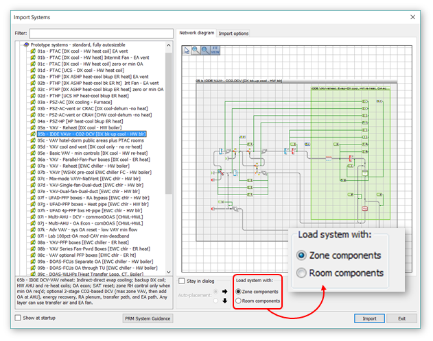
Settings in the ApacheHVAC Preferences dialog and the HVAC System Library Import dialog determine whether prototype systems will be loaded with Zones or Rooms and whether the Zone/Room placement tool will default to placing a Zone or Room component on the canvas.
When working with Zones, assignment of model spaces is by Zone or Zone Group. The group can be all zones on a system or any subset therefore, as might be desired for maintaining separate sub-groups within the Zone Groups.
Figure 2 - 1 : The default preference in ApacheHVAC is to load Prototype systems with Zone components. A radio button within the dialog allows users to load networks with Room components instead. A setting in the ApacheHVAC Preferences dialog allows users to change the default preference of the software.
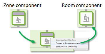
Figure 2 - 2 : Any Room Component on the network canvas can be converted to a Zone Components, or vice versa.
Direct acting units, radiators, and chilled ceilings can be added to spaces for heating and/or cooling purposes. Room units can be added to spaces contained within HVAC zones as well as directly to spaces in an un-zoned model. It is recommended that users work with Room components within ApHVAC, instead of Zone components, when large numbers of room units are to be implemented as editing of the units will be quicker and more efficient.
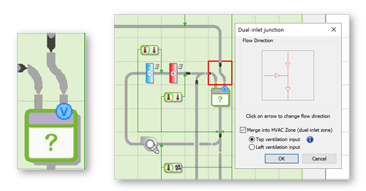
The air inlet of any Zone can be converted to a Dual-Inlet, with designated inlets for Ventilation and Space Conditioning. This is necessary for a system wherein Ventilation air is meant to be delivered separately to Rooms within multi-room HVAC Zones.* For example, in a dedicated outside-air system with ventilation air diffusers in each room and separately supplied airflow from zone-level fan-coil units, the apportioning of ventilation air and air for space conditioning needs to be separately determined.
Whereas distribution of air among rooms within a zone for space conditioning is by default according to the relative load in each space, the default basis for the distribution of Ventilation air among Rooms in a Dual-Inlet Zone is according to the relative floor area of the rooms.
*This is not needed when the space conditioning is at the Room level (as if there were a fan-coil unit in each room), as the rooms in that case would each need to be a separate zone with its own thermostat (i.e., air would not be distributed among rooms within a zone, as there would be just one room in each zone).
Figure 2 - 3 : A dual-inlet zone component is used when an HVAC Zone comprises rooms with Ventilation separately delivered to each room, and therefore this needs to be apportioned separately from the airflow for space conditioning.