ApacheHVAC Workflow using the System Parameters Interface
1) Set up HVAC zone groups and AHU/system groups in model.
2) Edit HVAC schedules and setpoints via the current System Schedules & Setpoints dialog.
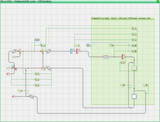
3) Load HVAC networks or Managed Systems (having a system frame) from the HVAC library.
4) Set up waterside loops, plant equipment, etc., as desired; or leave this step for later.
5) Set up prototype layers, if desired. This is an optional preparation similar to steps 6 and 7 below, but setting up multiplex layers and system parameters data for types of zone or layers, rather than for specific zones or layers. This can also be done ahead of time in saved user-library prototype systems.
6) Click the ‘Edit Multiplex’ toolbar button or double-click the top bar of the green multiplex frame in a system to assign model zones to the principal room/zone component on each multiplex layer. If prototype layers have been set up, assign zones accordingly to reduce the number of edits to be made later for individual zones or selected set of zones.
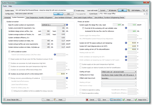
7) Click the ‘System Parameters’ toolbar button Double-click the gray system frame to perform edits in the System Parameters dialogs at the level of systems and zones to complete system set-up. ApacheHVAC User Guide part D: System Parameters Interface for HVAC Networks provides comprehensive and detailed guidance and information regarding this dialog.
8) Run Room/zone autosizing from HVAC toolbar button or from the ASHRAE Loads dialog.
9) Open the System Parameters dialog again for each system, or via the toolbar and then select the system to edit within the dialog to view and edit the following as needed:
· System input parameters, such as supply air temperatures;
· Zone-level loads, input parameters, and settings;
· Resulting autosized and derived parameters, such as required zone airflows, zone ventilation rates, system flow rates, and engineering checks.
10) Transfer the edits made in System Parameters dialogs to component level using the ‘Assign’ button.
11) Data can be directly edited at component level via individual component and controller dialogs, overriding settings passed down from the associated system parameters dialog. This may be necessary for departures from system prototypes or to edit parameters not included/editable within the System Parameters dialog. Direct component-level edits to any parameters that are editable in the System Parameters dialog will be overwritten by subsequent ‘Assign’ operations in System Parameters dialog.
Setting the system parameter link to ‘None <Select>’ will preserve any user edits of this nature, preventing them from being overwritten. Selecting any system parameter link or retaining the default link and clicking the ‘Re-apply’ button will override component-level edits.
12) Set up waterside loops, plant equipment, etc., if not already completed (step 4).
13) Run System-level autosizing from ApacheHVAC toolbar or from the ASHRAE Loads dialog.
14) View updated derivations as needed in the System Parameters dialog, as the autosizing of the supply fan according to simulated peak coincident flow on each network may have affected these. In some cases, it may be appropriate to override the autosized supply fan flow rate within the System Parameters dialog to match actual fan sizing and to address related engineering checks.
15) If necessary, adjust user setting and inputs, re-assign resulting values to components and controls, and re-run the system-level autosizing.
16) Inspect waterside/equipment dialogs for other autosized values, noting the effects of system sizing with respect to water loops, boilers, chillers, heat pumps, etc.
17) Generate and view System Loads and Sizing reports.
18) Perform simulations and view results.