Appendix A: Using the PRM Navigator with a substantially complete model
Using the PRM Navigator when starting with a completed model and HVAC system file for the proposed design, rather than starting within the navigator
Thermal modeling considerations
The following assumes that the model already had complete geometry, proper U-effective values in ground-contact constructions, infiltration rates, solar shading calcs, daylight sensor data and formula profiles assigned if daylighting controls are included, detailed internal gains and schedules defined, thermal templates assigned, possible modifications to Space Data, etc., and therefore it would not be appropriate to remove all custom thermal templates and re-assign the 90.1 space-by-space thermal templates.
Skip over steps not listed below, unless these have not been completed with respect to the proposed design model as an independent project.
Preliminary data set up:
1. Use the Prototype Data (ASHRAE Baseline) link in the navigator to acquire required grouping schemes, thermal templates, and other needed data.
2. Manually complete the Room/Zone Group Assignment step, sorting the spaces in the model into the appropriate groups with the 90.1 space-by-space methods Grouping Scheme.
Envelope Thermo-physical Properties:
3. Use the ASHRAE Baseline Constructions link in the navigator to acquire required constructions associated with the ASHRAE Climate Zone that is automatically determined by the set location and weather file for the project.
Room/Zone Thermal Template Data:
4. Room conditions (Setpoints, plus schedules and receptacle loads):
· Consistent with the sorting of spaces in the model into the appropriate groups with the 90.1 space-by-space methods Grouping Scheme, revise the heating and cooling Setpoints in a select subset of the Space-by-space thermal templates to match those of the thermal templates previously set up for the proposed design. Note that in both the proposed and the baseline thermal templates, the setpoints entered here should be the design heating and cooling set points that will be used for system sizing and which the heating and cooling proportional control bands will straddle.
· Consistent with the same sorting of spaces in the model, revise the schedules (profiles other than daylight dimming) for all internal gains in the baseline profiles to match those of the corresponding templates used in the proposed design.
· Consistent with the same sorting of spaces in the model, revise the Receptacle Equipment (computers, etc.) loads to be the same in the baseline as proposed, except when a difference between these is to be documented as an energy efficiency measure.
· These templates will need to be manually assigned to the Baseline model after it is generated (see below).
5. Exterior Lighting: Complete this step. The exterior lighting will be assigned to the last space on the Rooms list. While these lights will consume energy, there will be no gains to the space to which they are assigned.
6. Elevators: Use this step to add elevator energy consumption if appropriate and not yet included. Again, this will be assigned to the last space in the Rooms list. If elevators have already been included, this tool and the associated schedules that come with the PRM Prototype Data may be of use for improving the representation of elevator use.
7. Service Hot Water (DHW): The consumption rate(s) will have to be defined in one or more of the baseline thermal templates to match that of the proposed design model. Note that as of VE 6.1.1, users can select an independent profile for the consumption pattern (rather tan typing this to occupancy) and can thus put all DHW consumption in one profile for one space or space type, such as a restroom. When the independent profile is selected, the input changes from gallons per hour per person to simply gallons per hour. Whichever method is used, the baseline and proposed will need to be consistent. Also, note that is the proposed design model links the DHW loads to a boiler in ApacheHVAC, the same should be done for the baseline model.
ApacheHVAC System set up, loads, and sizing
The following assumes the starting point stated above and that ApacheHVAC system file was previously completed using the System Prototypes & Sizing navigator or similar VE features, and that this included the implementation of ASHRE 62.1 ventilation rates, if appropriate, via the spreadsheet. Given this, it is assumed that all system sizing has been completed and there are associated Loads Data spreadsheets that have already been generated for each system in the “proposed.asp” file.
8. Make backup copies of both the proposed HVAC system file and the associated Loads Data spreadsheets.
9. Use Edit Current Baseline to open the baseline prototype systems file, choose and copy as needed the appropriate baseline system types, delete unneeded systems.
10. While the Baseline.asp system is open, complete the assignment of spaces in the model to layers in the multiplex using the Assign from Room Group, as was very likely done previously for the proposed design.
11. AHU Parameters: This step will create Loads Data spreadsheets for each of the baseline systems in the Baseline.asp file and provides the opportunity to set any variance from default values for basic parameters. For example, if the ASHRAE requirement for the baseline system outside air economizer high-limit is 75, set this up to 75 from 70 for all systems to which it applies. Revise the AHU cooling coil LAT values so as to be 20 F below the space design cooling setpoint.
12. Again, it is assumed here that the proposed system has previously been set up, scheduled, sized, and tested. If this was completed using the System Prototypes & Sizing navigator or equivalent tools in the VE, the System Schedules dialog should already have been used to set values in the pre-defined system profiles accordingly.
13. Other Input Data: Complete set up of Renewable Energy Systems and Utility Tariffs as appropriate.
14. Generate the baseline model.
15. Check for proper set up of ground-contact constructions with a U-effective adjustment layer, reduction of overall glazing area (if the proposed design has more than 40% of the overall window-to-wall ratio for the entire building—not per facade—the glazing should have been reduced to 40%), and so forth.
16. For users with UFAD and DV systems or other thermally stratified environments in the proposed design, this is the time to remove the partitions with holes that separate occupied and stratified zones (or the potentially multiple sub-zones in an atrium that is meant to stratify).
17. If the proposed design model has a double-skin façade, this should also be removed at this time, as follows:
· Enter ModelIt and switch to Baseline model.
· Delete the double-skin façade geometry from the baseline model.
· Return to the BPRM view.
· At this point the newly exposed facade will have default VE constructions assigned. You must manually assign the baseline exterior wall constructions for this facade.
· Once the facade constructions have been assigned, the 0 deg baseline model geometry and construction assignment should now be correct.
· IF after removing the double-skin façade the overall window-to-wall ratio for the entire baseline building exceeds 40%, the newly exposed glazing on facades where the DSF was removed will need to be downsized until the overall 40% requirement is met. (If the proposed building had greater than 40% WWR prior to generating the Baseline building, the glazing area on all exterior facades will have been automatically reduced to meet the requirement.)
· For user that have previously generated the other baseline orientations by running Room Load Calculations after generating the baseline model, these other orientations must be refreshed. This is will be dealt with by running the Room Load calculations in a later step. As these other baseline orientations are based on the 0-degree baseline, there will be no need to repeat the steps above.
18. While in the BPRM view, select Baseline (vs. Proposed) from the drop-down menu on the toolbar. Then manually assign the 90.1 Space-by-space thermal templates to the baseline zones consistent with the sorting of spaces in the model into the appropriate groups with the 90.1 space-by-space methods Grouping Scheme. The grouping will allow efficient selection of multiple zones to which the same template is to be assigned.
19. Go to the Loads Data folder in the Project folder and open the spreadsheets in both the Proposed folder and the Baseline0 folder in matched pairs (one from each folder) for comparison.
20. Duplicate any changes in the changes previously made in the proposed sys spreadsheets, such as ACH rates and 100% transfer air designations for exhausted restrooms on the Room Design Airflows tab, and the space types on the 62.1 ventilation tab (if used) to the baseline version of each spreadsheet. Note that some things here will be specific to the proposed system, such as ventilation effectiveness or any departure from typical supply air temperatures, and should not be duplicated in the corresponding baseline system spreadsheets.
21. Close any spreadsheets for proposed systems that are still open.
22. Open all baseline system spreadsheets residing in the Baseline0 folder (the ones that would have been edited in the previous step above).
23. Calculate the baseline fan-power adjustment value for “A” according to ASHRAE 90.1 section 6.5.3.1.1—taking credit for ducted returns, MERV-13 filtration, energy recovery devices, direct evaporative cooling, etc.—as in the example below. Enter this value for “A” into the green cell under Baseline Fan Curve User Inputs on the appropriate Sys tab (for the baseline system number) in all spreadsheets in the Baseline0 folder, as appropriate. For example, the entry cell is U24 on the Sys 5,7 tab is this pertains to Baseline System type 5 or 7.
A = sum of (PD × CFMD/4131)
where
PD = each applicable pressure drop adjustment in i.w.c. from Table 6.5.3.1.1B
CFMD = the design airflow (i.e., from the actual design) in CFM through each applicable device (from Table 6.5.3.1.1B)
Example: If AHU-1 has a MERV 13 filter and a Heat recovery device with design static pressure of 1.2 i.w.c, both at a design flow rate of 20,000 cfm, then...
A = (0.9*20,000/4134) + (1.2*20,000/4134) = 10.2
Note that because the adjustments are relative to the design condition in the proposed system, these calculations can be performed prior to sizing the baseline systems. However, the spreadsheet still needs the results of the baseline system sizing to complete its calculation of the final fan efficiency values.
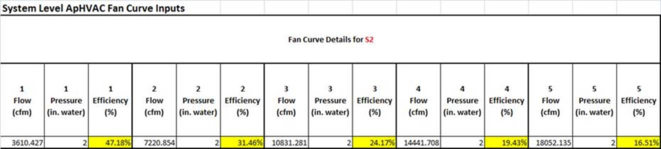
Entering a number in the spreadsheet for “A” will revise the fan efficiency for each of the five data points for Fan component (e.g., SA fan component S2 on the Sys 5,7 tab, as highlighted in the S2 table from that tab below). The static pressure values for the baseline supply fans will remain unchanged (e.g., at 2.0 i.w.c.). Because TSP is held constant in this calculation, and because the baseline SA fan power is accounting for ALL fans, other than parallel fan-powered boxes, in the baseline system, the resulting efficiency values will appear remarkably low, as in this example:
24. Close ALL spreadsheets.
25. Copy ALL revised spreadsheets in the Baseline0 folder to the other three Baseline Loads Data folders (Baseline90, Baseline180, Baseline 270).
26. Execute the Room Loads Calculation step. This will populate the spreadsheets.
27. Assign Room Sizing Data: Ensure that you did indeed make a backup copy of “proposed.asp” prior to executing the Assign Room Sizing Data step, which will populate the controllers in the systems with values form the spreadsheets (you will need this to occur for all baseline system, but presumably do not need it and very likely do not want it for the proposed system).
28. System Load Calculation: The dialog should have “proposed.asp” set as the linked HVAC file. This will then run five times automatically—one for the proposed and four more for the four Baseline systems.
29. For VE 6.1 through 6.2 and all intermediate versions, RATHER than proceeding to the next step, side-step a bug in this by manually transferring the final Fan efficiency values, as follows:
· The bug, which has been fixed for VE 6.2.1, writes the system re-heat coil sizes to the spreadsheet in the incorrect rows. Thus users of version prior to 6.2.1 should avoid using the “Update fan and coil sizing data” step in the navigator. Instead...
· Manually copy the revised efficiency values (after system sizing) from the Fan Curve Details for S2 table, as highlighted in the example above, to the corresponding S2 fan components in each of the four baseline systems (0, 90, 180, and 270). Note that this cannot properly be done prior to system sizing, as the calculation of these values depends upon the flow rates determined in the sizing (which determine the motor efficiency at design flow as selected automatically by the spreadsheet from a table of ASHRAE values for this parameter).
30. In VE 6.2.1 or newer versions, Update fan and coil sizing data will copy the revised fan efficiency values from the spreadsheets to the baseline systems. Again, these are calculated using a combination of values form the System Loads sizing run, the value for “A” that you calculated and entered, and values for motor efficiency at the design (autosized) flow rate from a lookup table that related motor size and efficiency, per ASHRAE 90.1.
31. Having completed the step above, you should now have ready-to-use baseline systems. You may want to review the System Sizing Reports at this time.
32. As the fan data in the proposed.asp system file will have been altered by the above (which you probably didn’t require if this was already set up properly), you will need to open the most recent HVAC system backup file and Save As “proposed.asp” before proceeding further. This simply resets proposed.asp back to the fully custom-built version.
Appendix B: Baseline system fan sizing details
Naming convention and fan-power determination for all fan components in PRM Baseline Systems:
· PRM Baseline Supply Fan {system fan power allowance, excluding special cases below, is calculated at the system-level SA fans for PRM Baseline Systems 3—8 and 11 according to the 90.1 App. G formulae laid out below and, for variable-volume systems, using the 90.1 App. G Baseline VAV fan curve to determine part-load fan power relative to the allowance at the design flow rate}
· PRM Baseline Fan for System 1 or 2 {Power = CFM x 0.3}
· PRM Baseline Parallel Fan-Powered Box for System 6 or 8 {Power = CFM x 0.35}
· PRM Baseline Return or Exhaust Fan {Power = 0; all inputs/calcs are overridden and Design Fan Power set to zero}
· PRM Baseline Supply Fan for System 9 or 10 {Power = CFM x 0.3}
· PRM Baseline Non-Mech Cool Fan for System 9 or 10 {Power = CFM x 0.054 for 90.1-2010 version of App. G PRM}
· PRM Baseline FCU Fan {Power = CFM x 0.3 for “system 11” DOAS + Fan-coil units; not defined by ASHRAE, but required by LEED EAc1 when proposed system is FCUs with central-plant CHW and HW}
While the reference name and flow rate remain editable and the design flow rate is autosized, all other inputs are disabled by presence of the PRM-specific fan component reference names defined above. The presence of these component names also triggers two essential PRM Baseline fan functions:
· Calculate fan power in accordance with all PRM fan system applications defined above.
· For supply fans in systems 3–8 and 11, automatically obtain the value “A” from the spreadsheet for adjustment of baseline fan power according to the sum of pressure-drop (PD) credits associated with the proposed fan system and use the 90.1 App. G calculations below.
The last of the special Baseline fans above is not yet included in any prototype system, but is required for 90.1-2010. Note that I have also edited the name for the PRM Baseline FCU Fan to differentiate this from the OA Supply Fan in the FCU systems.
In any fan component using the name PRM Baseline Supply Fan—i.e., all but the special cases noted above—the system fan power allowance at the supply air (SA) fan will be calculated according to SA fan flow rate and 90.1-2007 PRM table G3.1.2.9 Baseline Fan Brake Horsepower and section G3.1.2.9 System Fan Power, as laid out below.
Baseline fan break horsepower (bhp) allowance for Constant-volume PRM Baseline fan in system 3–4
bhp = CFMS ⋅ 0.00094 + A
Baseline fan break horsepower (bhp) allowance for Variable-volume PRM Baseline fan in system 5–8 and 11
bhp = CFMS ⋅ 0.0013 + A
CFMS = the maximum design supply airflow rate to conditioned spaces served by the system in cubic feet per minute
hp = the maximum combined motor nameplate horsepower
bhp = the maximum combined fan brake horsepower
A = sum of (PD × CFMD/4131)
where
PD = each applicable pressure drop adjustment from Table 6.5.3.1.1B in in. w.c.
CFMD = the design airflow through each applicable device from Table 6.5.3.1.1B in cubic feet per minute
System Fan Power allowance for PRM Baseline fan in system 3–8 and 11
P fan = bhp × 746 / Fan Motor Efficiency .
where
P fan = electric power to fan motor (watts)
bhp = CFM s ⋅ 0.0013 + A
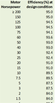
Fan Motor Efficiency = the efficiency from Table 10.8 for the next motor size greater than the bhp using the enclosed motor at 1800 rpm.
CFMS = the baseline system maximum design supply fan airflow rate in cubic feet per minute (cfm)
During System-level sizing, Motor Efficiency at Design Flow Rate for SA fans in PRM Baseline systems 3–8 and 11 is provided by the following lookup table of values from ASHRAE 90.1-2007 Table 10.8 Enclosed Motors column 4: