Algorithm & Airflow Control
Controller Algorithm
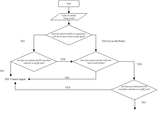
Shown below is a flow chart illustrating the decision making process followed by a controller. Not all controllers use every step of the process. For example, a time switch controller does not use a sensor and will proceed directly to the time switch profile decision.
The independent controller with sensor and independent differential controller have tick boxes for set point and proportional control. At least one of these boxes must be ticked to provide some feedback for the controller. If only set point is ticked then the controlled component will attempt to maintain the value at maximum control signal when the controller is ON and no control will be maintained when the controller is OFF. If we assume a controller is being used to control airflow and both the set point and proportional check boxes are ticked then:
· When the controller is OFF, flow at this node is zero.
· When the controller is ON:
o If under proportional control, the flow rate at this node will depend on the value corresponding to the control signal coming from the proportional controller at any instant in time.
o If not under proportional control, the flow rate at this node will depend on the value specified for the maximum control signal.
Normally the only reason for using both the set point and proportional tick boxes on the same controller is in order to allow the signal for the set point to be modified by AND or OR connection. However, an exception applies in the case of radiators and chilled ceilings. If proportional control is used for these components the controller must have the set point box ticked, and its control parameters must be such as to give an ON signal when the device is scheduled to operate.
Figure 6 - 5 : On-Off control logic. Note: This logic diagram does not yet include the capability for allowing OR connections to override the OFF state of a time switch. See section 6.6.7 above.
Airflow control
In the case of airflow control, the node where the flow is controlled may be anywhere in the network; it is not necessary to make any control connections at the fan in order to establish system airflow rates. As an example of controls more generally, the controls affect the airflow as follows:
A flow controller, in common with controllers of other system variables, has an on/off state that is a governed by its profile and any AND or OR connections attached to it.
When the controller is OFF, the flow at the controlled node is zero.
When the on/off controller is ON:
· If proportional control is set, the flow rate at the node will depend on the value corresponding to the control signal generated by the proportional controller.
· If proportional control is not set, the flow rate at the node will depend on the value specified for the maximum control signal.
Flow rate is subject to a further type of control that does not apply to other controlled variables. Flow rate is not only switched between on and off states by the control profile – it is modulated by it. Thus if the percentage flow controller has a value of 70% at a particular time, the flow value calculated from the control parameters will be multiplied by 0.7. This feature has been introduced to provide additional flexibility in flow specification.
For other controlled variables, the Time Switch profile is interpreted as an on/off switch, being on when the profile has a value greater than 50% and off otherwise. This principle applies whether or not proportional control is used.
Once a controller has been used to establish the flow rate at a node, the program feeds that information forwards and backwards along the air distribution path until it reaches a junction (i.e. it assumes the flow rate into any component equals the flow rate out, except at junctions). At junctions, the program must know the flow rates at all the connected nodes except one. It can then calculate the unknown flow from the known ones. In this way the program can calculate the flow rates at every point in the system, provided there are sufficient controllers appropriately positioned.
It is usually sufficient to place flow controllers only at those nodes which are immediately upstream of rooms, and at one other node to establish the ratio of outside to recirculated air. From this, the program can work backwards through the system network calculating the flow rates elsewhere by addition and subtraction at junctions.
In constant volume systems the ratio of outside air can be controlled without the use of a damper component by simply specifying the absolute value of flow rate at the outside air inlet. In variable air volume systems it is typically necessary to use a Damper set component in the fresh air inlet to control the percentage of outside air. At the node immediately downstream of a damper set, either percentage flow control for the outside air branch or a target dry-bulb temperature for the mixed air must be used to control the outside air ventilation rate (in as much as it exceeds the minimum setting in the damper).
In some systems – for example dual duct systems – additional flow controllers are required to specify flows in the system branches.
If flow rates cannot be calculated at all nodes, an error will be reported. For the full set of rules on setting flow rates see Appendix A: Rules for airflow specification.