Working with controllers on the airside HVAC network
The toolbar buttons used to place controllers on the airside network are as follows:
Independent controllers
· time switch
· controller with sensor
· differential controller
Dependent controllers
· time switch
· controller with sensor
· differential controller
AND connection, OR connection
Following the selection of a controller from the toolbar, you first choose the controlled node. For most components that are placed on the airside network, a controller is required and the controlled node should be the node immediately downstream of the component. A few components, however, do not require a controller. For airflow, and only in the case of airflow, the controlled may be any node on the system branch to which the controlled flow rate applies. Typically it will not be a node immediately adjacent to a fan component. Next you place the controller, and finally (where applicable) the sensed node or nodes.
The following is a summary of considerations for placing controllers; however, there are important rules that do need to be followed in the case of multiplexed controls. These are clearly laid out in the section on Multiplexing.
Placement of controllers:
· Most components – Control is required at the downstream node adjacent to the component in order for the component to function.
· Fans and Ductwork heat pickup – These two components have characteristic performance that relates to the airflow passing through them, but neither should be directly controlled.
· Divergent “T” junctions – One of two downstream branches for a flow-splitting “T” junction can be controlled, via the immediately downstream node on that branch, as a percentage of the flow entering the junction. The flow on that branch cannot, however, also be otherwise controlled by another controller.
· Airflow – Provide control on each branch representing a unique path for which the flow rate cannot otherwise be determined, but do not over-constrain the system.
· Air-source heat pumps – while this component is placed on the network (typically at an air inlet) so as to read the source temperature, it does not need a controller, as it is only reading the air temperature and otherwise acting as a heat source for coils, radiators, etc. that have their own controls.
· Heat recovery – The heat-recovery/exchange component is unusual in that is has two downstream nodes. In this case, either one of the two, but not both, may be controlled.
It is not necessary to define local control loops at individual components. Indeed, it is likely to cause control instability if you control a variable as a direct function of a value measured at the same node. For example, if you want a heating coil to warm an airstream to 25 ° C, do not control heat output in response to the measured off-coil air temperature. Instead, you should control temperature directly.
Ideally, all feedback control loops should have a slow responding component such as a room somewhere in the loop. There will be occasions when this is not possible (for example when the ratio of outside air to return air is controlled as a function of the mixed air temperature); in such cases damping can be added to the proportional controller to encourage control stability, but you should check the program output carefully to ensure that the system is behaving correctly.
Once controllers are in place their behavior may be modified with AND and OR connections from other controllers.
On/Off, Deadband, and Proportional control
· It is essential for users to understand the differences between On/Off, Deadband, and Proportional control. Illustrations of each of these, plus relationship between airflow and SAT controls, are provided below in relation to these controller types.
Multiple control of single variable
· It is permissible and often highly desirable to have multiple controllers “vying” for control of the same controlled variable for a component or flow rate.
· Where multiple controllers are used, whether multiplexed or manually placed, they must all point to one node and must all control the same variable—e.g., it would not be acceptable to point a target dry-bulb temperature control and a percentage flow control both to the downstream node of a single mixing damper set. In the case of airflow control, while the controlled node can be anywhere on a branch, multiple controllers must all point to the same node such that they can “vote” on the flow rate for that branch of the network.
· The general rule for multiple controllers is that whichever “votes” for the value that represent more output from the component or branch will “win” the vote. Indeed, while the vote for the lowest leaving air temperature will always “win” in the case of a cooling coil, for all other components and airflows, it is the high value that will “win” the vote—i.e., whichever controller is asking for more heat, more air, more moister, a higher percentage, or a higher flow rate will win.
Controller operation
All controllers have a time switch profile and some types respond to one or more sensed variables. They output two types of control signal: switching signals and numerical control signals. The switching signal is either ON or OFF, depending on the sensor signal and sensor parameters. The numeric control signal (if present) will be a variable such as the required off-coil temperature of a heating coil. For flow controllers, the time switch profile has a special interpretation allowing it to take values intermediate between ON and OFF. This modulating feature for flow control proves useful in certain situations. For example it allows the minimum flow rate for an outside-air damper set to follow the time-variation defined in a profile.
The switching signal is used to switch equipment on and off, and may also be passed on as an input for another controller via an AND or OR connection.
The numeric control signal sets the value of a physical variable such as temperature or flow rate. This may modulate under proportional control.
Controllers are of three basic types: Time switch controller, Controller with sensor, and Differential controller. Each type has Independent and Dependent variants:
Independent controllers directly control a component or airflow rate. They also generate a switching signal which can be used as an input to other controllers via AND and OR connections.
Dependent controllers generate only a switching signal for input to other controllers.
With the exception of ducts, passive junctions, rooms and fans, every HVAC component needs a controller. Controllers are also required to set airflow rates, and this may be done at any node (not necessarily at a fan). Controllers switch components on or off and govern their performance. System variables that may be controlled include airflow, heat output, temperature and humidity.
Controllers are required throughout the ApacheHVAC model to control the system components and to move air through the network. The control may be no more than a simple time switch (on at certain hours of the day, off at others). In other cases it will modulate the operation of a component in response to conditions sensed by a thermostat or other type of sensor.
The following components will operate only if a control connection has been made to their downstream node:
· Heating coil
· Cooling coil
· Spray humidifier
· Steam humidifier
· Heat recovery device
· Mixing damper set
The downstream connection is interpreted as a connection to the component itself, and causes it to control the condition at the controlled node. Note that Fans are not directly controlled; flow rate is controlled anywhere on a network branch (See section 3.5 Airflow controllers, below).
Controller parameters
The following parameters feature in controller specifications:
· Node Being Sensed
· Variable Being Sensed
· Percentage Profile for Time Switch
· Value for Maximum Control Signal
· Value for Minimum Control Signal
· Constant or Timed Set point
· Set point
· Deadband
· High Sensor Input
· Logical 'OR' Control Combination
· Logical 'AND' Control Combinations
· Variable Being Controlled
· Constant or Timed Midband
· Midband
· Proportional Bandwidth
· Maximum Change per Time Step
The selection and application of parameters differs depending on the controller type. If a controller is required simply to hold a variable at a constant value, the controller specification need only include the value to be maintained and the hours during which the value is to be maintained. It will act as a simple time switch with the variable held constant as specified for ‘value for maximum control signal’ whenever the controller is the “ON” state. For example, to simulate a heating coil with a constant leaving air temperature requires only a controller to activate the coil over the required period and to set the off-coil temperature.
Where it is required to switch a device ON or OFF in accordance with the value of a sensed variable, the controller specification will include a set point and other parameters, such as a control deadband (hysteresis). This type of control would be typical for a thermostat controlling a room heater. It may also be augmented by proportional control (see below) if, in this example, the output of the heater is variable. The controller set point can be constant or can vary according to an absolute profile. A time varying set point can be used to specify night setback and certain types of optimum start algorithm—e.g., using a formula profile to vary the time for changing from night setback to the occupied-hours set point according to the outdoor temperature.
Proportional controls are used where there is need for continuously varying the control value in relation to a sensed signal. This will be typical for control of VAV boxes, demand-controlled ventilation, bypass dampers for heat recovery, and so forth. They can also be used very generically to control one flow in proportion to another, such as in an active chilled beam for which the induced airflow is to be 2.5 times the primary airflow, regardless of the primary airflow rate. A similar application would be the approximation of exfiltration through a pressurized building envelope at a rate, for example, of 1.8% of the primary airflow to each zone.
For any controller that includes a sensor for either set-point control or proportional control, the sensed variable can be any of those available (see list below) and ultimately will depend upon the sensor location. For example room temperature, CO2, relative humidity, etc., outdoor variables, such as wet-bulb temperature, dew-point temperature, etc., or relative variables, such as the difference in enthalpy between return air and outdoor air.
Controlled variables
This parameter, which is present for all independent controllers, specifies the variable—flow rate, dry-bulb temperature, relative humidity, etc.—to be controlled at the controlled node. The control variable being must be consistent with each component: for example, you cannot control humidity with a heating coil. The table below lists variables available for control for each type of component.
|
Component
|
Applicable control variables for each type of component on the airside HVAC network
|
|
Dry-bulb Temp.
|
Relative Humidity
|
Wet-bulb Temp.
|
Dew-point Temp.
|
%
Flow
|
Heat Transfer
|
Moisture input
|
Enthalpy
|
Flow rate
|
|
Heating coil
|
Yes
|
No
|
No
|
No
|
No
|
Yes
|
No
|
No
|
No
|
|
Cooling coil
|
Yes
|
No
|
No
|
Yes
|
No
|
Yes
|
No
|
No
|
No
|
|
Heat recovery
|
Yes
|
No
|
No
|
No
|
No
|
No
|
No
|
No
|
No
|
|
Spray chamber
|
No
|
Yes
|
Yes
|
Yes
|
No
|
No
|
Yes
|
No
|
No
|
|
Steam humidifier
|
No
|
Yes
|
No
|
No
|
No
|
No
|
Yes
|
No
|
No
|
|
Mixing damper set
|
Yes
|
No
|
No
|
No
|
Yes
|
No
|
No
|
Yes
|
No
|
|
Return Air damper
|
n/a
|
n/a
|
n/a
|
n/a
|
n/a
|
n/a
|
n/a
|
n/a
|
n/a
|
|
Divergent junction
|
No
|
No
|
No
|
No
|
Yes
|
No
|
No
|
No
|
No
|
|
Active duct
|
n/a
|
n/a
|
n/a
|
n/a
|
n/a
|
n/a
|
n/a
|
n/a
|
n/a
|
|
Fan
|
n/a
|
n/a
|
n/a
|
n/a
|
n/a
|
n/a
|
n/a
|
n/a
|
n/a
|
|
Network branch
|
No
|
No
|
No
|
No
|
No
|
No
|
No
|
No
|
Yes
|
Table 6 - 1 : Controlled variables allowed for each type of component—i.e., at the network node immediately downstream. As an example, Percentage Flow Rate is permitted only at the outlet of a damper set or at one outlet of a divergent (flow-splitting) junction. However, dry-bulb-temperature and enthalpy are also permitted at the outlet of a mixing damper set, where they are interpreted as targets to be achieved, to the extent this can be done by mixing the available inlet streams.
Note that Active Duct components are not controlled at all, Fan components are not directly controlled, and flow rate can be controlled anywhere on a network branch.
Sensed variables
The following variables are available for sensing in all controllers with sensors:
· Flow rate
· Dry-bulb temperature
· Relative humidity
· Wet-bulb temperature
· Dewpoint temperature
· Enthalpy
· CO 2 concentration
If the sensed variable is dry-bulb temperature, the sensor radiant fraction must also be specified.
Sensed CO 2 concentration in a space at any simulation time step is a function of the outdoor concentration (assumed to be 360 ppm), CO 2 addition from occupants, and the extent to which the mechanical system recirculates the air and/or mixes it with air from other spaces. Occupant CO 2 production is, in turn, a function of the number of occupants in the space and the occupant activity level in keeping with combined sensible and latent gain per person that has been set for People under Internal Gains in the Thermal Conditions template or Space Data dialogs. CO 2 concentration is not available for Room Unit controllers, as these control only hydronic devices that cannot influence room air CO 2 concentration.
Two additional sensed variables are available for room unit controllers:
· Solar radiation
· Surface temperature
For Solar radiation, Sensor location must be External and the orientation and slope of the receiving surface must be specified.
Note: While Flow rate is on the Room Unit controller selection list of Sensed variables and does cause gpm or l/s units to be displayed, this sensed variable is not yet available for Room Unit controllers.
Error limits for the three additional parameters:
|
Radiant Fraction
|
0.0 – 1.0
|
0.0 – 1.0
|
|
Orientation (azimuth)
|
0.0 – 360.0
|
0.0 – 360.0
|
|
Slope (angle from horizontal)
|
0.0 – 180.0
|
0.0 – 180.0
|
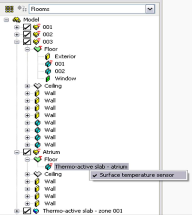
Surface temperature sensors require a room/zone location to be selected within the controller dialog. For the sensor to function, this location requires a tag to be set in Apache Thermal view indicating which adjacency in the zone/room should have the sensor.
For example, for a room with a floor that overlaps multiple other zones, just one section of the floor can be tagged as the sensed surface within that room.
The selected adjacency can be within a non-occupied space, such as a return or underfloor supply plenum. In the case of a hydronic heated or cooled slab, the sensor would go on the floor or ceiling of the adjacent occupied space, such that it is measuring the temperature of the thermo-active surface that occupants can see.
Figure 6 - 2 : Adding a surface temperature sensor tag
The surface temperature sensor tag is added by selecting the appropriate adjacency while in the Apache Thermal view and then right clicking to access the surface temperature sensor option. Once set, a red “T” will be displayed next to the adjacency, parent surface for that adjacency (typically a floor or ceiling), and the room or zone that contains that surface. See
Figure 6-2 , above.
Controls in combination
Multiple controllers at a single network node
It is permissible to attach more than one controller to a node. Multiple controls are used, for example, to determine an overall control signal based upon the most extreme condition occurring in a set of zones. Requirement for using multiple controllers to determine an overall control signal:
· All controllers must be attached to the same node.
· All the controllers must control the same variable.
Where two or more controllers are attached to one node, their on/off control signals and their controlled variable values are combined as follows:
· The component (or flow) is turned on if any (one or more) of the attached controllers outputs an ON signal.
· Any controller providing an ON signal also outputs a value for the controlled variable, which is then subject to a polling process.
The effect on the controlled variable depends on the type of this variable and the component it applies to. In the case of flow control, the flow through the node is set to the maximum of the flows calculated by the attached controllers. In the case of a damper set, this principle applies to the flow calculated for the branch entering the mixing box from the left on the schematic (which often represents the outside air intake). In the case of a heating coil, steam humidifier, spray chamber, or heat recovery device, the controlled variable (for instance, off-coil temperature) is set to the maximum of the controlled values output by the attached controllers. In the case of a cooling coil, the controlled variable is set to the minimum of the controllers’ output values. As such, the multiple attached controllers effectively “vote” on the resulting control value. The resulting outcomes described above are summarized Table 3-2, below.
|
Component
|
Dominant control value when multiple controls point to a single network node
|
|
Dry-bulb Temp.
|
Relative Humidity
|
Wet-bulb Temp.
|
Dew-point Temp.
|
%
Flow
|
Heat Transfer
|
Moisture input
|
Enthalpy
|
Flow rate
|
|
Heating coil
|
Max
|
–
|
–
|
–
|
–
|
Max
|
–
|
–
|
–
|
|
Cooling coil
|
Min
|
–
|
–
|
Min
|
–
|
Min
|
–
|
–
|
–
|
|
Heat recovery
|
Max
|
–
|
–
|
–
|
–
|
–
|
–
|
–
|
–
|
|
Spray chamber
|
–
|
Max
|
Max
|
Max
|
–
|
–
|
Max
|
–
|
–
|
|
Steam humidifier
|
–
|
Max
|
–
|
–
|
–
|
–
|
Max
|
–
|
–
|
|
Mixing damper set
|
Max
|
–
|
–
|
–
|
Max
|
–
|
–
|
Max
|
–
|
|
Return Air damper
|
n/a
|
n/a
|
n/a
|
n/a
|
n/a
|
n/a
|
n/a
|
n/a
|
n/a
|
|
Divergent junction
|
–
|
–
|
–
|
–
|
Max
|
–
|
–
|
–
|
–
|
|
Active duct
|
n/a
|
n/a
|
n/a
|
n/a
|
n/a
|
n/a
|
n/a
|
n/a
|
n/a
|
|
Fan
|
n/a
|
n/a
|
n/a
|
n/a
|
n/a
|
n/a
|
n/a
|
n/a
|
n/a
|
|
Network branch
|
–
|
–
|
–
|
–
|
–
|
–
|
–
|
–
|
Max
|
Table 6 - 2 : The dominant value when multiple controllers point to a single node or component.
Linking of controllers via logical AND and OR connections
Controllers may be linked together via AND and OR connections (further described in sections 3.5.4 and 3.5.5 below). The final control signal may be the result of a relatively complex series of logical determinations. The control of a room heater could, for example, be specified as follows:
· Heat is ON during the day, provided that the outside air temperature is below 15 ° C, AND
· During the night, whenever the room temperature drops below 10 ° C, AND
· During the preheat period, starting at a time which depends on outside air temperature (i.e. optimum start control).
Airflow controllers
To set the system airflows, is not necessary or desirable to connect controls to every node in the network. Rather, it is necessary to provide just enough control to determine airflow rates for all branches. Whenever possible, users should let ApacheHVAC derive the flow. For example, when multiple controlled branches converge, so long as all branch flows are defined, ApacheHVAC should be left to derive the flow on the collector/return path.
The program does check for both over-specification of flow rate and for negative flows. Therefore, if flow rates are incorrectly set up, it will very likely be flagged as a error that will prevent the simulation from running. In all such cases, flagged errors include report the node number at which the flow error is occurring. In any case, it is best to control flow at the minimum number of points needed to define the system.
Equipment output is determined by the parameters setting the controlled value at the minimum and maximum control signal. The component capacity does not feature in the control provided that the capacity equals or exceeds the values entered for minimum and maximum control signal.
Controller parameters—terminology and general discussion
The following section describes the parameters and terminology used throughout the range of ApacheHVAC controllers. Separate sections following this describe specific types of controllers and their applications.
Time Switch or On/Off Control
This first section of the control dialog (common to all types of controllers) determines what is being controlled, the control value at maximum sensed signal (or simply the set value if there is no proportional control), and the inclusion of a profile or schedule to determine when the controller is active.
Variable Being Controlled
This parameter, which is present for all independent controllers, specifies the variable—flow rate, dry-bulb temperature, relative humidity, etc.—to be controlled at the controlled node.
It is not necessary to define local control loops at individual components and, indeed, it is likely to cause control instability if you control one variable at a node as a direct function of a value measured at the same node. For example, if you want a heater coil to warm the air up to 25 ° C, do not control heat output in response to the measured off-coil air temperature. Instead, you should directly control temperature.
Ideally, all feedback control loops should have a slow responding component (e.g. a room) somewhere in the loop. There will be occasions when this is not possible (e.g. when the ratio of outside air to return air is controlled as a function of the mixed air temperature). In such cases damping can be added to the proportional controller to encourage control stability, but you should check the program output carefully to ensure that the system is behaving correctly.
None of the 'active' components defined in the network (with the exception of fans) will perform a function unless a controller is specified at the node immediately downstream of that component. The controls react with the components as follows:
When the controller is OFF, a particular component will have no effect on the air passing over it. If the airflow on a network branch is OFF, there will be no load placed upon any components on that particular branch. If the airflow ALL downstream network branches are OFF, there will be no load on any components located on the upstream path that feeds them.
When the controller is ON:
· If under proportional control, the condition of the air leaving the component will depend on the value corresponding to the control signal coming from the proportional controller at any instant in time.
· If no proportional control, the condition of the air leaving the component will depend on the control value indicated at the maximum sensed signal.
Value at Maximum Signal
This parameter is present for all independent controllers. It has a different function for on/off (set point) controllers and proportional control.
In the case of on/off control, which applies when the Proportional Control box is not ticked, the value for maximum signal specifies the numerical control signal. The controlled variable will take this value whenever the switching signal is on (provided that such a value can be achieved within the physical constraints, which include the maximum duty of the component).
In the case of proportional control, which applies when the Proportional Control box is ticked, the value for maximum signal specifies the value of the numeric control signal output when the sensed variable is at or above the upper end of the proportional band.
The response characteristic for proportional control is shown in Figure 6-4 and Figure 6-11 , below.
Note that if you want to control the temperature of the air from a heating or cooling coil, this should be done directly by choosing dry-bulb temperature for the ‘variable being controlled’ cell and the required temperature for ‘value for maximum control signal’. ApacheHVAC will calculate the heat needed to maintain this temperature (subject to the limit imposed by the capacity of the component). The same principle applies to the control of relative humidity, wet-bulb and dewpoint temperatures by cooling coils and humidifiers.
Time Switch Profile
You must specify a percentage profile to indicate the schedule of operation for the controller.
For most types of controlled variable this is interpreted as follows.
When the profile has a value greater than 50% it will be ON, subject to other parameters that may override the time switch. Otherwise, it is OFF. The controller output is always off when the profile value is less than or equal to 50%.
An exception to this rule applies in the case of air and water flow controllers. Here the profile has a modulating rather than just a switching role, the profile value being applied as a factor on the flow rate.
Sensor (for on/off and proportional control)
The section of the controller inputs that determine the sensed variable and characteristics of the sensor, such as radiant fraction, in the case of temperature sensors.
Variable Being Sensed
Select the variable that is to be monitored at the sensed node. This will be fed into the on/off (set point) or proportional control.
Radiant fraction
When the sensed variable is dry-bulb temperature, an input field is available to set the radiant fraction of sensed temperature. As an example, if the radiant fraction were set to 0.5, the sensor would effectively be sensing dry resultant temperature—i.e., operative temperature in still air conditions.
Set Point (for on/off control)
Active
Tick this box to enable on/off control. This may operate in conjunction with, or as an alternative to, proportional control. On/off control must be enabled for direct acting heaters, radiators and chilled beams.
Set Point Variation
The set point for on/off control may be constant or variable. Select Constant or Timed as appropriate.
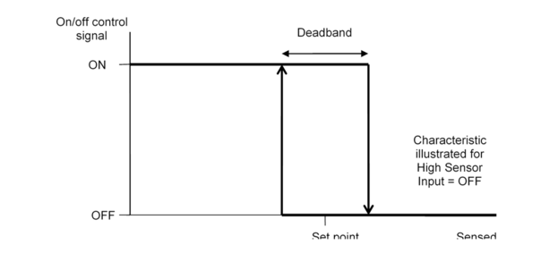
Figure 6 - 3 : On/off (set point) control characteristic
Set Point
Set Point defines the behavior of the switching signal generated by the controller as a function of the sensed variable when on/off control is used. The response characteristic for on/off control is shown in Figure 6-3 and Figure 6-12 .
A constant value for Set Point is entered as a number and a variable value by an absolute profile specifying the value of the set point throughout the year.
The units in which the values are expressed must be appropriate to the variable being sensed, and when the set point is entered directly, the value must lie within the appropriate warning and error limits shown below:
Deadband
Deadband defines the range of sensed variable values over which switching occurs in on/off control. The response characteristic for on/off control is shown in Figure 6-3 and Figure 6-12 .
The deadband enables the program to model switching hysteresis. If it is specified as zero the control will switch between the ON and OFF states whenever the value of the sensed variable passes through the set point. If a non-zero deadband is specified, the control will change its state as the sensed variable rises through the upper end of the deadband or falls through the lower end of the deadband.
High Sensor Input
This parameter relates to on/off (set point) control and specifies whether the switching signal output by the controller is ON or OFF for high values of the sensed variable. The response characteristic for on/off control shown in Figure 6-3 and Figure 6-12 is drawn for the case where High Sensor Input set to OFF. When this parameter is set to ON the characteristic is inverted.
Heaters and humidifiers usually have High Sensor Input set to OFF so that the device switches off at high values of sensed temperature or humidity. Cooling coils, whether used for cooling or dehumidification, usually have High Sensor Input set to ON.
Proportional Control
Active
Tick this box to enable proportional control.
Proportional control features are used within the ApacheHVAC system model to allow components to mimic the operation of real controls. Proportional control usually gives better quality control than on/off (set point) control—i.e., it is generally more stable and provides better maintenance of the target value for the controlled variable.
Proportional control is used to adjust the value of a controlled variable smoothly as a function of the value of a sensed variable. Examples of this type of control are the modulation of a VAV supply airflow rates and CAV supply temperatures.
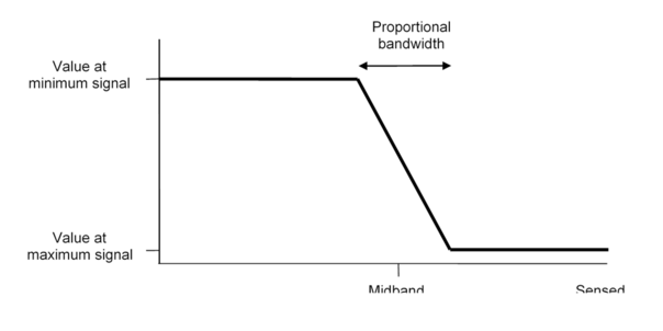
Figure 6 - 4 : Proportional control characteristic
Midband Variation
The midband for proportional control may be constant or variable (‘timed’). Select Constant or Timed as appropriate.
Midband
The midband parameter specifies the value of the sensed variable at the center of the proportional band (see Figure 6-4 above). A constant value for midband is entered as a number. A variable value is provided by an absolute profile specifying the value of the midband throughout the year.
Proportional Bandwidth
The proportional bandwidth is the width of the band used for proportional control - that is, the movement in the sensed variable between the values that generate the maximum and minimum control signals. This proportional bandwidth is centered about the midband.
The response characteristic for proportional control is shown in Figure 6-4 above, and further described using examples in relation to Figure 6-11 .
By way of illustration, if a heater coil is being controlled on outside air temperature, such that at an outside temperature of -1 ° C requires an off heater temperature of 35 ° C, and at 10 ° C outside the off heater temperature is reduced to 28 ° C, then the midband would be 4.5K (4.5 ± 11/2=10,-1), and the proportional band would be 11K (10-(-1)=11). It should be noted that the value for the minimum control signal would be 35 ° C, and for the maximum control signal, 28 ° C.
ApacheHVAC can model simple switching (on/off) control and ideal proportional control. Because ApacheHVAC simplifies the HVAC system it can model the 'ideal' translation of a control signal directly to the required change in a physical quantity. In this respect, ApacheHVAC proportional control is actually closer in reality to real PID and direct digital control than it is to real proportional control.
In reality, to control the heat input from a heater coil, a sensor might be positioned somewhere in the system and configured to adjust the position of a valve which varies the flow of hot water through it. The controls engineer will choose a control system which gives the most precise match of control signal (measured temperature) to required condition (heat input). In a well designed control system, there will be a one to one correspondence.
ApacheHVAC proportional controllers model this situation because a control signal can be translated directly into heat input or off-coil temperature according to a linear relationship, without any of the lag typically introduced by the water side of the system.
Maximum Change per Time Step
This parameter specifies the maximum fractional change that the controller can carry out in each simulation time step. The fraction is with respect to the overall range of control between the value at Max signal and the value at Min signal.
This parameter provides a form of damping and should be adjusted to a lower value in situations where a closed-loop feedback between the sensor and controller may cause 'hunting'. The program will try to automatically compensate for this type of control instability, but it is advisable to take steps to avoid the problem arising.
Never use a feedback loop to control a component when open loop could be used instead. When closed-loop feedback control is essential or valuable, there are a number of precautions that will facilitate control stability:
· Ensure that the controlled components are not oversized or that the range of controlled values is no greater than is necessary to meet design conditions;
· Keep proportional bands as wide as is reasonable and appropriate;
· If possible, include a room in the loop (the mass of air and materials in a room provides very much slower response times than other components)
· Specify a small value for the 'maximum change per time step' (e.g. 0.05 to 0.2)
Note that the effect of the maximum change per time step value entered will vary depending on the time step. Thus if you change the time step you should also change the value entered here.
Value at Minimum Signal
The value for minimum control signal applies to proportional control only. It specifies the value of the numerical control signal output when the sensed variable is at or below the lower end of the proportional band.
The response characteristic for proportional control is shown in Figure 6-4 above, and further described using additional examples in relation to Figure 6-11 .
Example:
A controller is sensing temperature in a room with a midband of 22 ° C and a proportional bandwidth of 4K and the airflow at a node is to be controlled to 500 l/s when the room is at 20 ° C and to 1500 l/s when it is at 24 ° C. Here the value for minimum signal is 500 and the value for maximum signal is 1500.
Note that the distinction between a direct acting and a reverse-acting proportional control is made by exchanging the value at minimum signal with the value at maximum signal. The value at minimum signal is generated for low values of the sensed variable and the value at maximum signal for high values of the sensed variable.
AND Connections
The effect of AND connections is to permit a controller to generate an ON signal only when its own switching signal AND all controllers coupled to it via AND connections are generating ON signals.
To create an AND connection, click on the AND connection toolbar button, then the controller generating the signal, and finally the controller receiving the signal. AND connections attached to the current controller are listed in the dialog, and may be deleted using the Remove button.
This type of logical combination is useful, for example, when a system has a different mode of operation in summer and winter, with automatic switchover as a function of outside air temperature. The summer/winter switch can be described as two controllers; further controllers can be AND-combined with the summer or winter controllers.
The signals from all OR connections are computed before combining the result with signals from any AND connections.
OR Connections
The effect of an OR connection to a controller with a sensor is to make the controller generate an ON switching signal if either its own on/off controller OR the signals from one or more other attached controllers is ON.
To attach an OR connection click on the ‘OR connection’ button and drag a line from the controller generating the signal to the controller receiving the signal. OR connections can be applied to all controllers with sensors (independent, differential, or dependent), but not time switch controllers.
OR connections do not override the Time Switch Profile for the controller. When the Time Switch Profile is OFF the switching signal is OFF.
The signals from all OR connections are computed before combining the result with signals from any AND connections.
OR connections are less commonly used than AND connections. One application is in frost protection, where they can be used to detect when any one of a set of rooms falls below a given temperature threshold.
OR connections attached to the current controller are listed in the dialog, and may be deleted using the Remove button.
Allow OR inputs to override time switch?
This modifies the behavior of the AND/OR logical evaluation, allowing any OR input to override the OFF state of the time switch. Thus, when this option is ticked, it is possible for a controller with its time switch set to OFF to generate an overall ON signal, provided at least one of the OR connection inputs is ON.
This has the consequence that for controllers without sensors, it is possible to attach OR connections when this checkbox is checked (but not possible when the checkbox is unchecked).
In the case of controllers with sensors, the checkbox causes the logical value of the sensor and the logical value of the time-switch to be treated on an equal footing: Either the time-switch and setpoint control (when included) must both be ON, or at least one OR connections must provide and ON signal to generate an overall ON state for the controller (subject, of course, to any AND connections also being ON).
For new controllers as of VE 2012, this option is checked by default. For controllers in ApacheHVAC systems created before VE 2012, it is unchecked by default. Thus the older systems will behave as they did in the version in which they were created.