Independent & Dependent Controllers
Independent Time Switch Controller
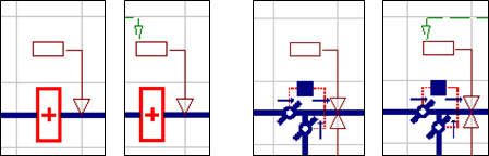
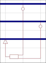
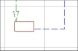
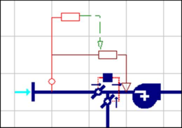
Figure 6 - 6 : Independent Time Switch Controllers (without and with an AND connection)
This is the simplest type of controller. It controls a variable at a constant value at prescribed times (subject to physical feasibility and the optional addition of AND connections). When it is attached immediately downstream of a component such as a heating coil it controls the coil in such a way as to set the off-coil temperature, provided this is feasible given the on-coil condition, the airflow rate and the coil’s capacity.
The term independent is used to denote that the controller feeds its signal directly into a component (in this case a preheat coil and a mixing damper set). Independent controllers generate two types of signal: a switching signal and a numerical signal. The switching signal turns the controlled device on or off and the numerical signal indicates the value to be set for the controlled variable.
The switching signal is ON when the time switch profile is ON (subject to provisos detailed below). The numerical signal is the value of the parameter ‘V at maximum signal’, where V denotes the controlled variable.
AND and OR connections attached as outputs from the controller may be used to feed its switching signal into other controllers.
If AND connections are input to an independent time switch controller they affect the switching signal in the following way.
The controller gives an ON signal when, and only when:
· the time switch profile is ON
and
· all the input AND connections (if any are present) are ON
AND and OR connections only convey a switching signal, not a numerical signal.
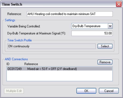
Figure 6 - 7 : Example parameters for Time Switch Controller
In the example shown in Figure 6-7 the switching signal will be ON at all times, provided the switching signal from the controller named “Mixed-air < 53°F = OFF (2-F deadband),” which is coupled by an AND connection, is also ON. The numeric control signal will then be 53°F. The independent time switch controller has been illustrated here first using temperature control as an example. When the controlled variable is airflow rate, as in Figure 6-8 ) two special conditions apply.
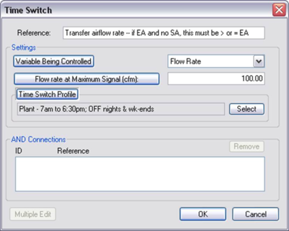
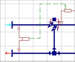
Figure 6 - 8 : Time Switch Controller with Flow Rate as controlled variable
First, an airflow rate controller may be attached to any airflow path on the network, where it will have the effect of setting the flow to the numerical control signal.
Second, the time switch profile has a special function in airflow control. Rather than being interpreted as ON (as denoted by a value greater than 50%) or OFF (other values), the profile is treated as a modulating function multiplying the numerical control signal. This feature can prove useful as a means of setting time-varying flow rates.
Independent Controller with Sensor
This type of controller responds to a variable sensed at a system node. It includes a time switch and options for both ON/OFF set-point control and proportional control. These options can be used in combination, if desired.
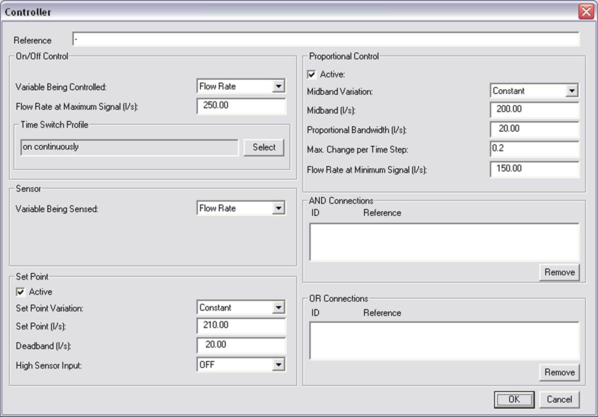
Figure 6 - 9 : Independent Controller with Sensor
This type of controller responds to a variable sensed at a system node. In the case illustrated in Figure 6-9 , the controller monitors room temperature and feeds its signal into a heating coil on the primary air supply to the room.
After placing the controller, select the controlled node (indicated by an arrow), followed by the sensed node.
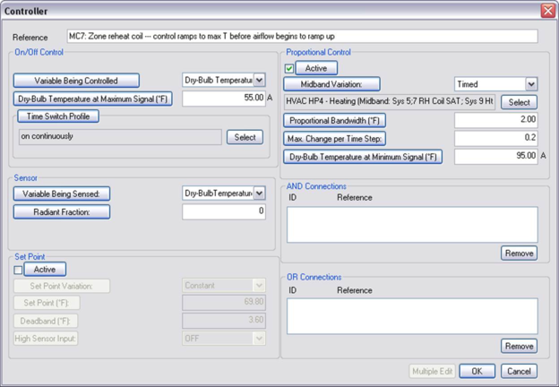
The control parameters shown in Figure 6-10 are set up to provide proportional control. When the Time Switch Profile is on, the off-coil temperature is adjusted between 28°C and 14°C – the values set for the parameters Dry-bulb temperature at minimum signal and Dry-bulb temperature at maximum signal – as the room air temperature varies over a proportional band centered on 20°C (the midband) and with a width of 2K (the proportional bandwidth).
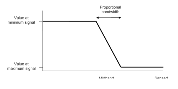
The control characteristic for proportional control is shown graphically in Figure 6-11 .
Figure 6 - 10 : Example parameters for Independent Controller with Sensor
Figure 6 - 11 : Proportional control characteristic
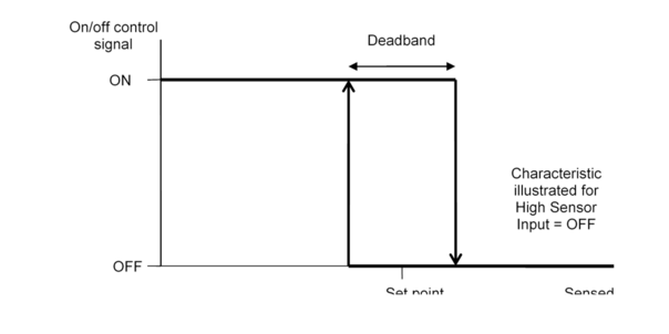
In the preceding example the set-point control has been turned off in favor of proportional control. Set point (on/off) control is an alternative to proportional control in which the signal fed into the controlled device can take only two values: ON or OFF. The control characteristic for on/off control is shown in Figure 6-12 .
Figure 6 - 12 : On/off (set point) control characteristic
The state of the on/off controller switches between ON and OFF as the sensed variable rises through the upper limit or falls through the lower limit of the deadband. Within the deadband the signal retains its current value. The characteristic gives rise to hysteresis: the value of the control signal in the deadband depends on the history of the sensed variable as well as its current value.
The overall shape of the on/off characteristic is set by the parameter High Sensor Input. If this is OFF (as in Figure 6-12 ) the signal is OFF at high values of the sensed variable. If it is ON the characteristic is inverted.
The on/off logical control signal is subject to modification by optional AND and OR connections feeding into it. These connections also govern the operation of the controller when proportional control is used. The controller gives an ON signal (and operates in proportional control mode) when, and only when:
the time switch profile is ON
and
the on/off control signal, or at least one OR connection, is ON, or
the on/off (set point) control is not ticked
and
all the input AND connections (if any are present) are ON
AND and OR connections attached as outputs from the controller may be used to feed its switching signal into other controllers.
Proportional controls sequencing
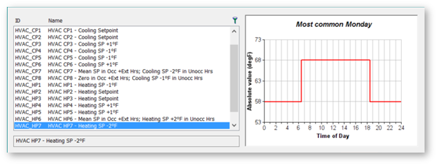
The standard System HVAC Profiles are named to clarify values relative to setpoints, making it easier to apply and modify these profiles for custom airside control sequencing.
Figure 6 - 13 : System HVAC profiles referenced by systems in the Prototype Library
Coordination of zone cooling airflow and cooling supply air temperature (SAT) reset at the system cooling coil according to zone demand provides an instructive example of how and why controls should be sequenced.
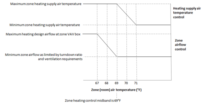
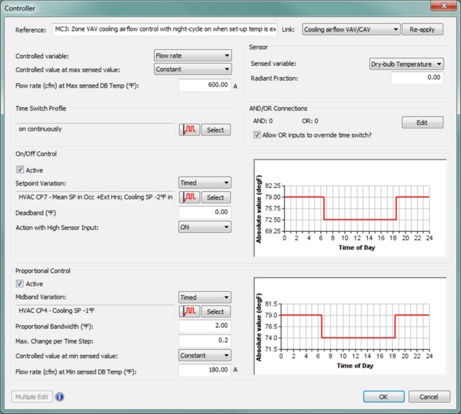
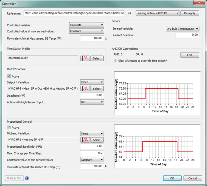
Figure 6-14 and Figure 6-15 first a graph plotting the functions of these controllers with respect to the room temperature and then Figure 6-16 and Figure 6-17 illustrate the controller input dialogs for typical VAV cooling airflow control and SAT reset. To keep the visualization clear, the nighttime setback and fan cycling for unoccupied hours via timed midbands have been omitted from the graph shown here (see the sections on Prototype Systems and System Sizing toward the end of this user guide for more information). The graph shows only how the two controllers would function during occupied hours.
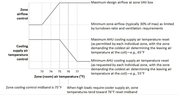 Figure 6 - 14 : Plot of typical VAV cooling airflow control and SAT reset.
Figure 6 - 15 : Plot of typical VAV heating airflow control and SAT reset.
Figure 6 - 16 : Controller inputs for typical VAV cooling airflow control.
Figure 6 - 17 : Controller inputs for typical VAV heating airflow control.
Independent Differential Controller
Figure 6 - 18 : Independent Differential Controller
The independent differential controller takes as its input the difference between variables sensed at two system nodes. In other respects it behaves like an independent controller with sensor.
After placing the controller, select the controlled node (indicated by an arrow), followed by the two sensed nodes. The order of selecting the sensed nodes is important: the input signal is the value at the node selected first minus the value at the node selected second. On the graphic the first-selected node is shown attaching to the control box below the second-selected node.
This type of controller is used less often than the dependent differential controller. In the case illustrated in Figure 6-18 and Figure 6-19 , it senses the difference between flows sensed in two network branches and sets a third flow equal to this difference when it is positive.
Figure 6 - 19 : Example parameters for Independent Differential Controller
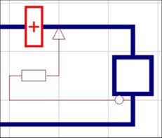
Dependent Time Switch Controller
Figure 6 - 20 : Dependent Time Switch Controller (shown with both with input AND connection and output OR connection)
This controller operates like the independent time switch controller, but is not directly attached to a component. Its purpose is to generate a switching signal to be fed into one or more other controllers via AND and OR connections. The control signal is a function of the profile and any input AND connections.
Dependent Controller with Sensor
Figure 6 - 21 : Dependent Controller with Sensor (with output AND connection)
This controller operates like an independent controller with sensor but is not directly attached to a component. Its purpose is to generate a switching signal to be fed into one or more other controllers via AND and OR connections. The switching signal is a function of the profile, the sensed variable any input AND or OR connections. Proportional control is not an option with this type of controller, as it does not generate a numeric control signal.
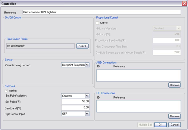
Figure 6 - 22 : Example parameters for Dependent Controller with Sensor
In the example shown in Figure 6-22 , the controller monitors outside dew-point temperature and gives an ON signal when it exceeds 56°F. In this case, there is no deadband, as the control will not influence the outdoor air condition, and thus there will be no possibility of a feedback loop.
Dependent Differential Controller
Figure 6 - 23 : Dependent Differential Controller (with output AND connection)
The dependent differential controller takes as its input the difference between variables sensed at two system nodes. In other respects it behaves like a dependent controller with sensor. A common use for this type of controller is to detect whether fresh air is warmer or cooler than return air as the basis for recirculation decisions.
After placing the controller, select the two sensed nodes.
The order of selecting the sensed nodes is important: The input signal is given by the value at the first node selected minus the value at the second node selected. As of VE 2012, the bulb symbol for the sensor at the first node is larger than the bulb at the node selected second. In Figure 6-23 , the first sensed node is shown attaching to the control box below the second sensed node. This will always be true, regardless of the left-hand vs. right-hand orientation of the differential controller box.
In the case illustrated in Figure 6-23 and the first of the two example control dialogs in Figure 6-24 , the controller senses the difference between temperatures in the return and fresh air inlet ducts and returns an ON signal if the return air enthalpy is greater than the outside air enthalpy. This signal is fed, via an AND connection, into the damper set controlling outside air intake.
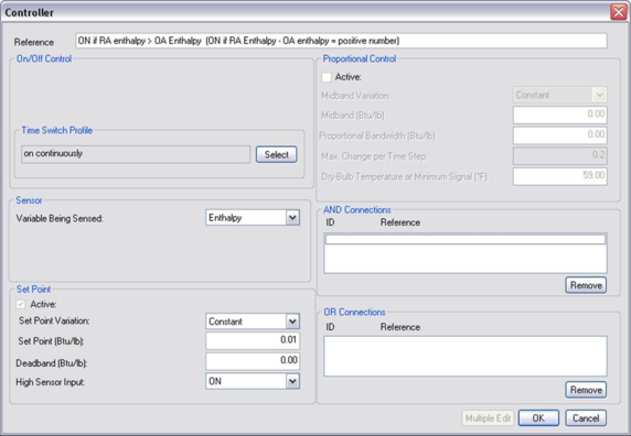
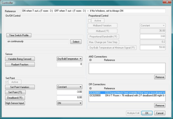
Figure 6 - 24 : Example parameters for Dependent Differential Controllers: The first (top) generates an ON signal if Enthalpy Sensor 1 – Enthalpy Sensor 2 = positive value greater than 0.01. This is typical of damper controls intended to introduce more than the minimum outside air only when it has a lower enthalpy than the return air. The second (bottom) example generates an ON signal if the value at the outdoor air Temperature Sensor is greater than or equal to the value at a room temperature sensor – 3 ° F. This is a typical control for mechanical fan systems in mixed-mode building that are intended to operate only when the conditions are unfavorable for natural ventilation (e.g., when the outside air is not at least 3 ° F cooler than the room air). This second example also includes OR connections to dependent controllers with sensors meant to override it (providing an ON signal when this controller would otherwise not do so) if either the room temperature exceeds an elevated setpoint or a CO2 threshold, in either case suggesting that the windows are not open when they should be or that, despite favorable outdoor temperatures, there is not enough air movement to meet cooling or ventilation demand via the operable windows.
Note that while the “Setpoint” value when sensing temperature (DBT, WBT, or DPT) will be expressed in °K (indicating a differential) when in metric units mode, in IP units the differential will be expressed in °F, as there is no differential IP unit for temperature.